1997 HONDA CIVIC Power mirrors
[x] Cancel search: Power mirrorsPage 1682 of 2189
Power Mirrors
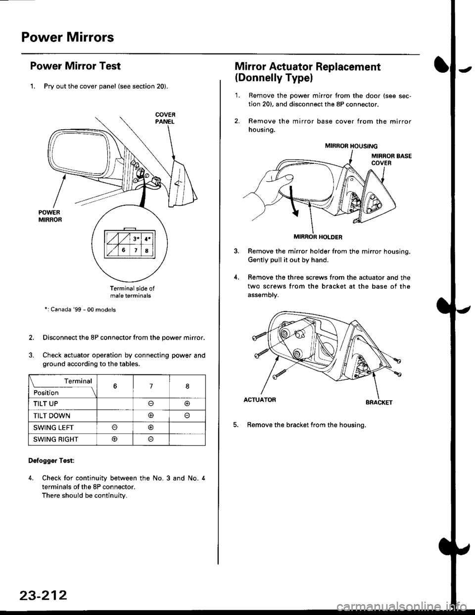
Power Mirror Test
1. Pry out the cover panel (see section 20).
Terminalside ofmale terminals
*: Canada '99 - 00 models
Disconnect the 8P connector from the power mirror.
Check actuator operation by connecting power and
ground according to the tables.
Dofogger Test:
4. Check for continuity between the No. 3 and No. 4
terminals of the 8P connector.
There should be continuity.
COVER
L___r"'ry1Position67I
TILT UPo@
TILT DOWN@
SWING LEFTo@
SWING RIGHT@
23-212
Mirror Actuator Replacement
(Donnelly Typel
'1. Remove the power mirror from the door {see sec-
tion 20). and disconnect the 8P connector.
2. Remove the mirror base cover from the mirror
housing.
MIRROR HOLDER
Remove the mirror holder from the mirror housing.
Gently pull it out by hand.
Remove the three screws from the actuator and the
two screws from the bracket at the base of the
assemory.
BRACKET
5. Remove the bracket from the housinq.
4.
MIRROR HOUSING
Page 1817 of 2189

Contents
How to Use This Manual ICircuit Schematics (see Circuit Index)Fuse/Relaylnformation 6Ground-to-Componentslndex 6-6ComponentLocationPhotooraohs 201Conriector Views 202
Circuit Index
Accessory power socket 155Air conditionerAir delivery'96198 models 61'99-'00 models 61-2Blower controls'96198 models 60'99100 models 60-1Compressor controls 62Fans 63Anti-lock brake system (ABS) 44A/T gear position indicatorCVT 89All except CVT 89-1Automatic transmission controlsAll '96-'98 models except CVT and GX 39All '99100 models except CVT 39-8All GX models 39-8'96-'�98 CVT 39-4'99100 cw 39-12Back-up lightsCoupe and Sedan 110Hatchback l'10-1Brake lightsAll Coupes and'96-'98 Sedans 110-15'99-'00 Sedans 110-16Hatchback 110-17Brake system indicator light'96198 models 7'1'99100 models 71-1Ceiling light 114-3Charging system 22Condenser fan 63Console lights 114Cruise control 34Dash lights 114Daytime running lights 110- 13Engine coolant temperature gauge 81-1Fog lights 110-10Front parking lights 110-2Fuel gauge 81-1Fuse/relay boxUnder-dash 6Under-hood 6-4Underhood ABS 6-3Gauges 81Ground distribution 14Ground-to-Componentslndex 6-6Hazard warning lightsAll except '99100 Sedans 110-6'99100 Sedans 110-8Headlights 110-12Headlight switch 100Heater - See Air ConditionerHorn'96197 models 40'98 model 40-1'99100 models 40-2lgnition key reminder 73lgnition systemAll '96198 models except Dl685 20All '99100 models except D16Y5 with Mn 2O-2All D1685 engines 20-2'99-'00 D 16Y5 with M/T 20
lndicators 80Integrated control unit 70lnterlock systemAll except'96J98 CVT 138'96198CVT 138-1License plate lightsAll Coupes and '96-'98 Sedans I l0-3'99100 Sedans 1 10-4Hatchback 110-5Low fuel indicator light 74Moonrool'96197 models |22'98-'00 models 122-1Odometer 81Oil pressure indicator light 80-3Power distributionBattery to ignition switch, fuses, and relaysFuses to relays and components 10-2Power door locksAll models without keyless entry 130'96-'98 models with keyless entry 130-2'99100 models with keyless entry 130-12Power mirrorsWithout detogger 141With defogger '141-2
Power windows 120Programmed fuel injection system (PGNr-Fl)All '96-98 models except D1685 23All '99-'00 models except D16Y5with M/T and D1685 24All D1685 engines 25'99100 D16Y5 with M/T 23Radiator fan 63Rear window defogger'96-,98 models 64'99100 models 64-1Seat belt reminder 73Security system'96.'98 USA HX, LX, EX 133'96-'98 Canada EX, Si 133'99TOO USA HX, LX, EX, DX.V Si 133-4'99100 Canada EX, Si 133-4All CX and DX models 133-8Speedometer 81Starting systemA./T (All except Dl685) 21A"/r (D16Bs) 21-1Manualtransmission 21-2Slereo sound system 150Supplemental rastraint system (SRS) 47Tachometer 81TailliqhtsAllboupes and'96-'98 Sedans 110-3'99100 Sedans 1 10-4Hatchback 110-5Trunk light 114-3Turn signal lightsAll except'99100 Sedans 110-6'99-'00 Sedans 1 10-8Vehicle speed sensor (VSS) 33Wiper/washerFront 91Rear 92
10
Page 1835 of 2189
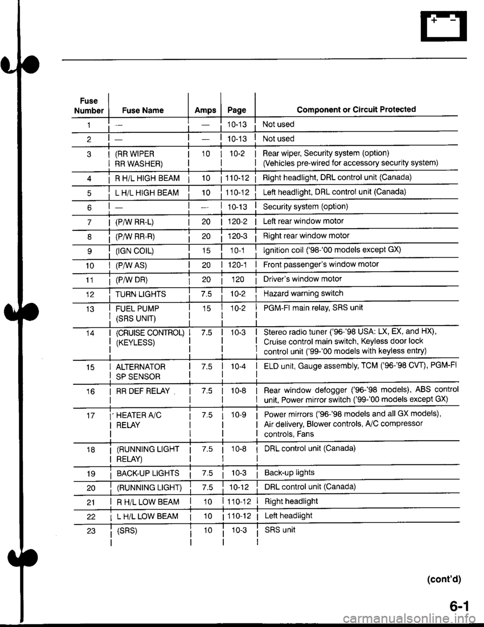
Fuse
NumberAmpsPageFuse Name
(RR WIPER
RR WASHER)
i R HiL HIGH BEAM | 10
L H/L HIGH BEAM
| (PAIV RR-L)
i (P/vv RR-R)
(rGN CO|L)
10I (P,^/V AS)
Component or Circuit Protected
Not used
Not used
Rear wiper, Security system (option)
(Vehicles pre-wired for accessory security system)
'10r 1n-2
I
| 1 10-12i Right headlight, DRL control unit (Canada)
Lett headlight, DRL control unit (Canada)
I ro-rsSecurity system (option)
| 120-2 | Left rear window motor
Right rear window motor
lgnition coil ('98-'00 models except GX)
| 120-1 | Front passenger's window motor
i (PiW DH)| 20 1 12O I Driver's window motor
TURN LIGHTSHazard warning switch
FUEL PUMP
(SRS UNIT)
PGM-FI main relav, SRS unit
(cRUrsE CoNTROL)
/KtrVt trSS\
Stereo radio tuner ('96-'98 USA: LX, EX, and HX),
Cruise control main switch, Keyless door lock
control unit ('99-'00 models with keyless entry)
15ALTERNATOR
SP SENSOR
l-a10-4I ELD unit, Gauge assembly, TCM (96-'98 CW, PGM-FI
16I RR DEF RELAY7.510-8I Rear window defogger ('96-'98 models), ABS control
I unit. Power mirror switch ('99-'00 models except GX)
i-HEATER r/C
I RELAY
Power mirrors ('96-98 models and all GX models),
Air delivery, Blower controls, AilC compressor
controls, Fans
I (RUNNING LIGHT
I RELAY)
1 7.5 1
tl
I DRL control unit (Canada)
i BACK-UP LTGHTSi Back-up lights
(RUNNING LIGHT)DRL control unit (Canada)
I R H/L LOW BEAM'10 l11o-12Right headlight
I L H/L LOW BEAM | 101110-12 | Left headlight
(cont'd)
(SRS)SRS unit
6-1
Page 1865 of 2189
Ground Distribution (cont'd)
1
- G551
Page
I
I
'96-'98 Models:
DRIVER'SwtNDowMOTOR
NOTE: Wires shown without color codes are black.
4
12091
I
I
c633
oRrvER'sDOOR LOCKACTUATORPage 130-1or 130-3
tl
tl
:f ;'*"
.--a ----
sl)
POWER WINDOWMASTER SWITCHPages 120, 120-1,120-2, and 120-3PHO|O AAvlEW 36
tl
tlL-----J
POWERDOORLOCKCONTROLUNITPage 130or 130-3
vlEW3/
tl
tl
4
c556
vtEw 61
8(SedanA4)
DRIVER'SDOORLOCKswrTcHPage 130or 130-3
tl
tl
,I
'-.o -.o -
POWERMIRRORswrTcHPage 141vlEw 33
ll
tl
4(withdefogger 2)
G55t
14-8
Page 2074 of 2189
Power Mirrors
- Without Defogger
r,-;;---j HEAIEF 1/ A/C FEIAY
I t uo s"" Po*", !f-----f Distribution, I
L_i:i:_J
UNDER-DASH
RELAYBOX
UNDER-OASHFUSE/RELAYBOX
I
I
I
I
I
BLK/BLU
10
BLK/BLU
-l
I
I
I
I
IJ
f,-G;---
I See Power
lF---t Distribution,
L_i:i'i_
rt;%,"
*'ii%.,
L vtEW 46
vlEw 22
'96-'98 modelsand all GX models
'99r00 modelsexcept GX
a-
c639
vlEW23
c656
POWERMIRBORswtTcHvtEw 33
See GroundDistribution,page 14-8.
LEFTMIRRORRIGHTMIRROR
G-t
BLU/BLK
('98 00mooets2't)15
BLU/ALK
LT GRN
G551
141
Page 2075 of 2189
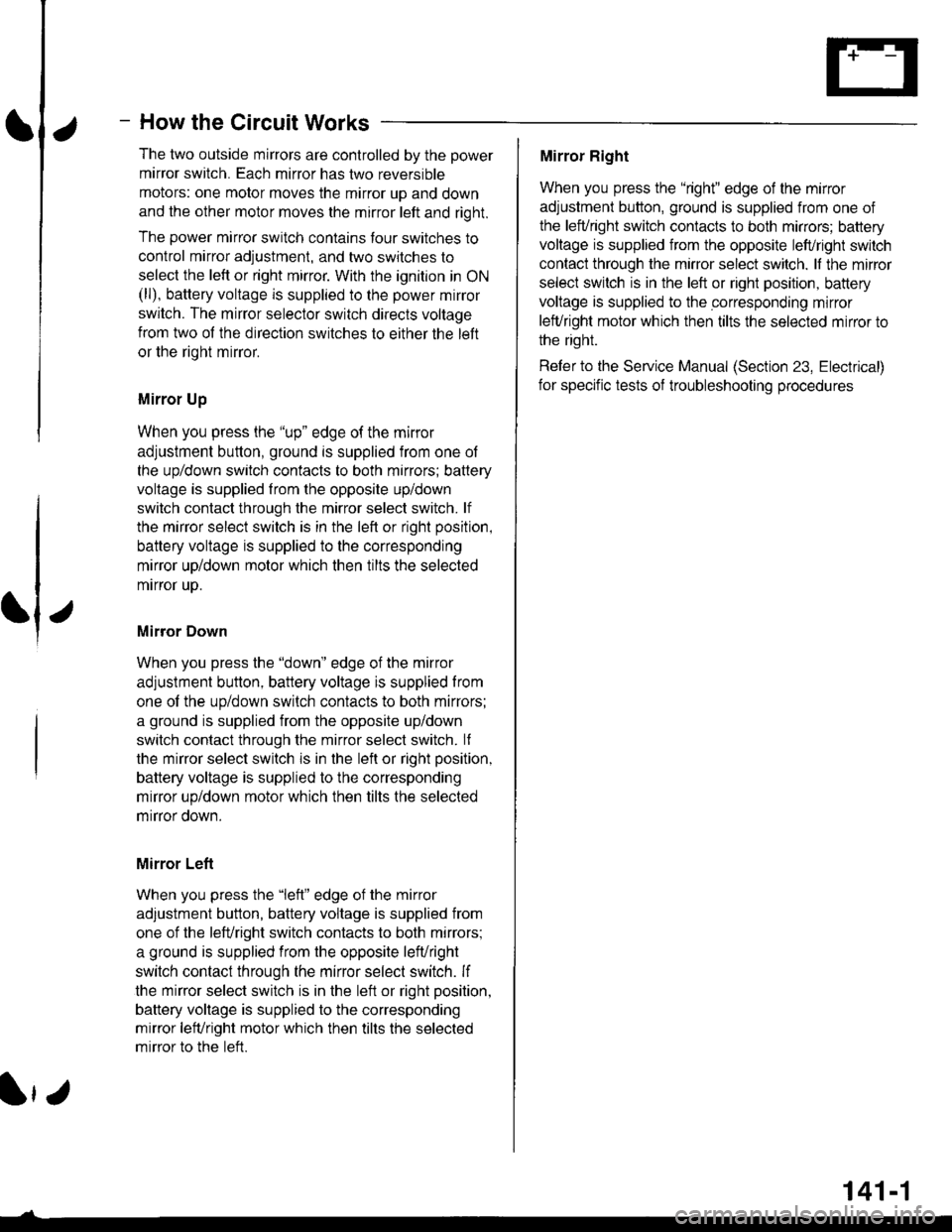
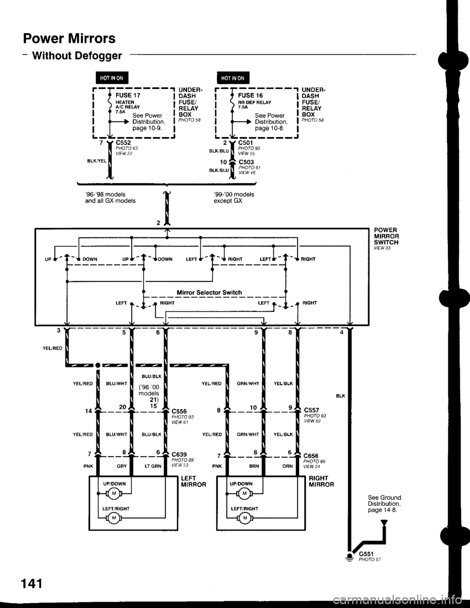
How the Circuit Works
The two outside mirrors are controlled by the power
mirror switch. Each mirror has two reversible
motors: one motor moves the mirror up and down
and the other motor moves the mirror lett and right.
The power mirror switch contains four switches to
control mirror adjustment, and two switches to
select the left or right mirror With the ignition in ON
(ll), battery voltage is supplied to the power mirror
swrtch. The mirror selector switch directs voltage
from two of the direction switches to either the left
or the right mirror.
Mirror Up
When you press the "up" edge of the mirror
adjustment button, ground is supplied from one of
the up/down switch contacts to both mirrors; battery
voltage is supplied from the opposite up/down
switch contact through the mirror select switch. lf
the mirror select switch is in the left or right position,
battery voltage is supplied to the corresponding
mirror uo/down motor which then tilts the selected
mtrror uD.
Mirror Down
When you press the "down" edge of the mirror
adjustment button, battery voltage is supplied Irom
one of the up/down swilch contacts to both mirrors;
a ground is supplied from the opposite up/down
switch contact through the mirror select switch. lf
the mirror select switch is in the left or right position,
battery voltage is supplied to the corresponding
mirror up/down motor which then tilts the selected
mrrror oown.
Mirror Left
When you press the "|eft" edge of the mirror
adjustment button, battery voltage is supplied from
one of the lefuright switch contacts to both mirrors;
a ground is supplied from the opposite lefuright
switch contact through the mirror select switch. lf
the mirror select switch is in the left or right position,
battery voltage is supplied to the corresponding
mirror lefvright motor which then tilts the selected
mirror to the lett.
Mirror Right
When you press the "right" edge of the mirror
adjustment button, ground is supplied from one of
the lefvright switch contacts to both mirrors; battery
voltage is supplied from the opposite left/right switch
contact through the mirror select switch. lf the mirror
select switch is in the left or right position, battery
voltage is supplied to the corresponding mirror
lefuright motor which then tilts the selected mirror to
the right.
Refer to the Service Manual (Section 23, Electrical)
for speclfic tests of troubleshooting procedures
141-1
Page 2076 of 2189
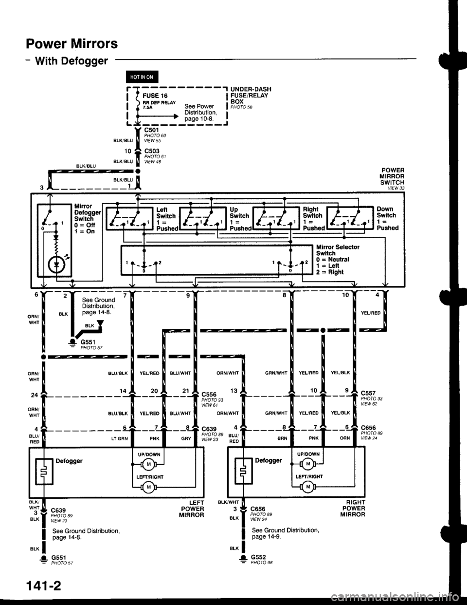
Power Mirrors
- With Defogger
ORN/
i I ;;;
- - - - - -
I HJ.o.',8.3.f;,"
i )tlf*"'*" geePower if,g}"",
!-,i::-i4tir-J
f 9;%.,BLKBLU I V'EW55
'o l9,;%,,BL(/B!U I V/EW 46
a
T'|[
aaa
OFN/
24
ORN/
BLU/RED
--
YEL/FED
20
--
BLUA!/HT
21cs56
OBN/WHf
c639 4
vtEw23 FEO
c557
vlEw 62
c656
ORN
BLK/
BLK
LEFT BLKryVHTPOWER 3MTRROR BLK
".* |..- Gs52
".^ |... G551
c639
vlEw2i
See Ground Distribution,page 14-8.
c656
vlEw 24
See Ground Dislribution,page 14-9.
Minor Selecto.SwitchO = Neutral1 = Lelt2 = Rlght
',41-2
Page 2077 of 2189
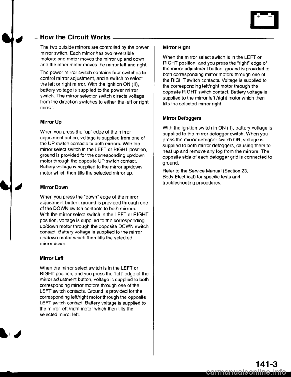
How the Circuit Works
The two outside mirrors are controlled by the power
mirror switch. Each mirror has two reversible
motors: one motor moves lhe mirror uo and down
and the other motor moves the mirror left and right.
The power mirror switch contains four switches to
control mirror adjustment, and a switch lo select
the left or right mirror. With the ignition ON (ll),
battery voltage is supplied to the power mirror
switch. The mirror selector switch directs voltage
Irom the direction switches to either the left or rioht
mtrror.
Mirror Up
When you press the "up" edge of the mirror
adjustment button, voltage is supplied from one of
the UP switch contacts to both mirrors. With the
mirror select switch in the LEFT or RIGHT Dosition.
ground is provjded for the corresponding up/down
motor through the opposite UP switch contact.
Battery voltage is supplied to the mirror up/down
motor which then tilts the selected mirror uo.
Mirror Down
When you press the "down" edge of the mirror
adjustment button, ground is provided through one
of the DOWN switch contacts to both mirrors.
With the mirror select switch in the LEFT or RIGHT
position, voltage is supplied to the corresponding
up/down motor through the opposite DOWN switch
contact. Battery voltage is supplied to the mirror
up/down motor which then tilts the selected
mtrror down.
Mirror Left
When the mirror select switch is in the LEFT or
RIGHT position, and you press the "lett" edge of the
mirror adjustment button, voltage is supplied to both
corresponding mirror motors through one of the
LEFT switch contacts. Ground is provided for the
corresponding lefvright motor through the opposite
LEFT switch contact, 8attery voltage is supplied to
the mirror left /right motor which then tilts the
selected mirror left.
I,J
141-3
Mirror Right
When the mirror select switch is in the LEFT or
RIGHT position, and you press the '?ight" edge of
the mirror adjustment button, ground is provided to
both corresponding mirror motors through one of
the RIGHT switch contacts. Voltage is supplied to
the corresponding leruright motor through the
opposite RIGHT switch contact. Battery voltage is
supplied to the mirror left /right motor which then
tilts the selected mirror right.
Mirror Detoggers
With the ignition switch in ON (ll), battery voltage is
supplied to the mirror defogger switch. When you
press the mirror defogger switch ON, voltage is
supplied to both mirror defoggers, causing them to
heat up and remove any fog from the mirrors. The
opposite side of each defogger grid is connected to
g rou no.
Refer to the Service Manual (Section 23,
Body Electrical) for specific tests and
troubleshooting procedures.