Page 1391 of 2189
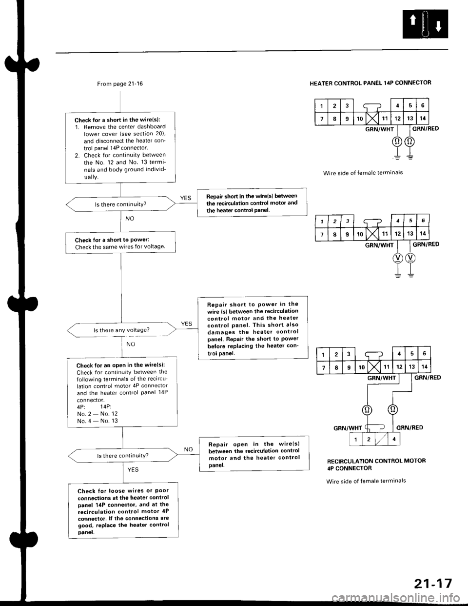
From page 21-16
ls there any voltage?
Check {or a short in the wire(s):1. Remove the center dashboardlower cover (see section 20),
and disconnect the heater con_
trol panel 14P connector'
2. Check for continuity between
the No. 12 and No. 13 termi-
nals and body ground individ-
Repair 5hort in the wire{sl between
the recirculation control motor and
the heater control Panel
Check Ior a short to Power:Check the same wires for voltage
Repair short to Power in the
wire {s) between the recirculationcontrol motor and the heater
control panel. This short also
damages the heater controlpanel. Repair the short to Powerbetore replacing the heater con-
trol panel.
Check lor an open in the wire(s):
Check for continuity between the
following terminals of the recircu
lation control motor 4P connector
and the heater control Panel 14P
4P. 14P:No.2 - No. 12No.4 No. 13
Repair open in the wirelsl
between the recirculation control
motor and the heater controlpanel.
ls there continuitY?
Check for loose wires or Poorconnections at the heater control
Danel 14P connector, and at the
recirculation control motor 4P
connector. lf the connections aregood, replace the heater control
Danel,
HEATER CONTROL PANEL 14P CONNECTOR
I;-?45
789'o lx11121314
GRN/WHT
0) (0
GRN/BED
Wire side of female terminals
GRN/RED
GRN/RED
RECIRCULATION CONTROL MOTOR
4P CONNECTOR
Wire side of female tetminals
I23i--?156
78I'olx11121314
GRN/WHT
V)(v
145
7IIrol\l rr1213
GRN/WHT
r zl/lt
21-17
Page 1392 of 2189
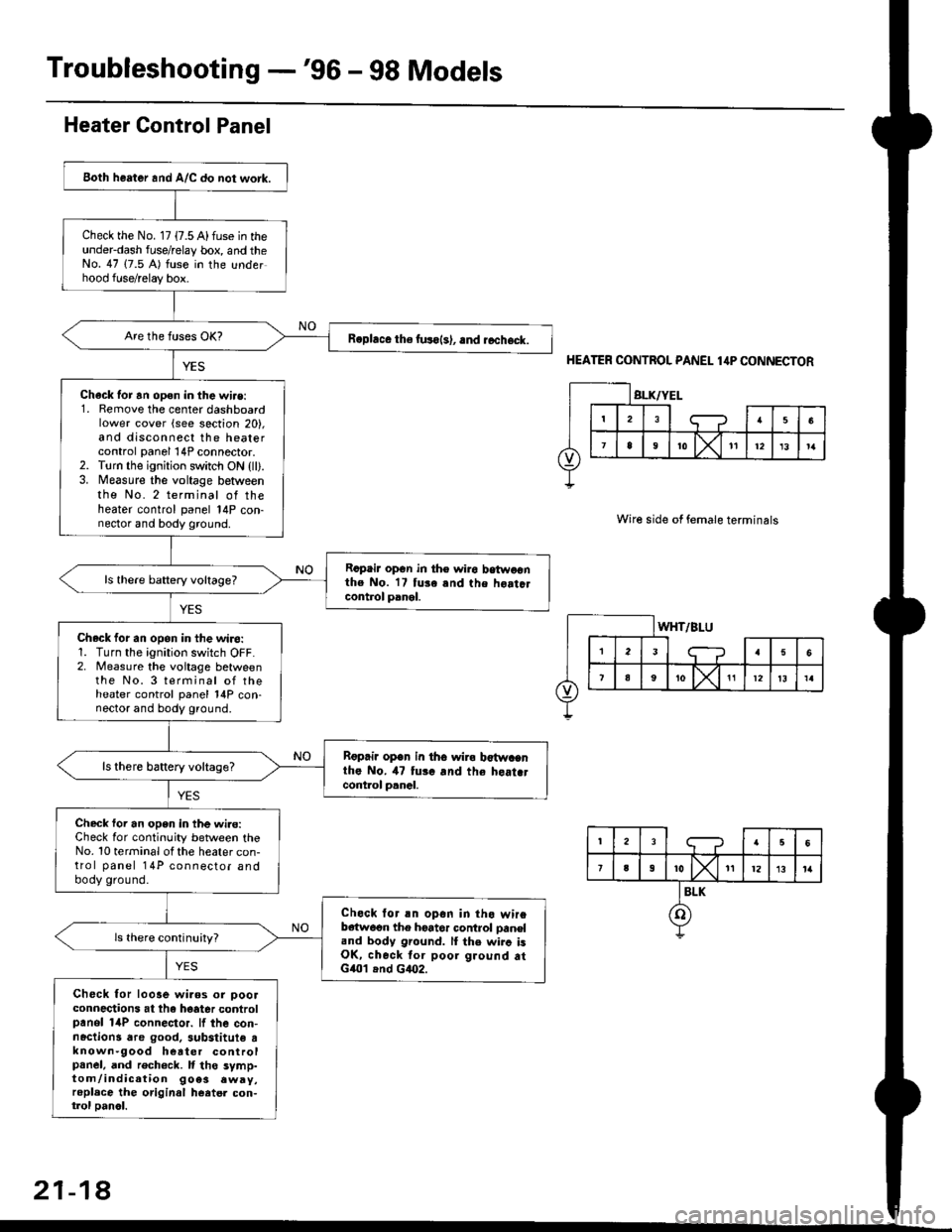
Troubleshooting -'96 - 98 Models
Both heater and A/C do not work.
Check the No. 17 {7.5 A) fuse in theunderdash fuse/relay box, and theNo. 47 (7.5 A) fuse in the underhood fuse/relay box.
R.phce the fuso{s), .nd rccheck.
Chack tor an open in the wi.e:1. Remove the center dashboardlower cover (see section 20),and disconnect the heatercontrol panel 14P connector.2. Torn the ignition switch ON {ll).3. Measure the voltage betweenthe No. 2 terminal of theheater control panel 14P con-nector and body ground.
Rcpair opGn in th€ wiro betwoonthe No. 17 tuse and the hoatclcontrol panel.
ls there baftery voltage?
Check for an opon in the wiro:1. Turn the ignition switch OFF.2. Measure the voitage betweenthe No. 3 terminal of theheater control panel 14P con-nector and body ground.
Rgprii open in th6 wira b€twacnthe No. il7 tui. and the heat.tcont.ol p.nal.
ls there battery voltage?
Check foi an open in the wi.e:Check for continuity between theNo. 10 terminal ot the heater con-trol panel 14P connector andbody ground.
Check lor an opon in tho wireb€{w6on the hoator control oaneland body ground. lI the wirc isOK, check tor poor ground atG401 .nd G4O2.
Check for looae wiaos or ooolconnections at the hoater controlpanol 14P connector. lf the con-nactions dre good. 3ubstitute tknown-9ood heater controlpanel, and rech6ck. It tho symp-tom/indication 9oe3 .wry,replace the original heatel con-trol oanol.
Heater Control Panel
HEATER CONTROL PANEL 1,lP CONNECTOR
Wire side of female terminals
21-18
Page 1416 of 2189
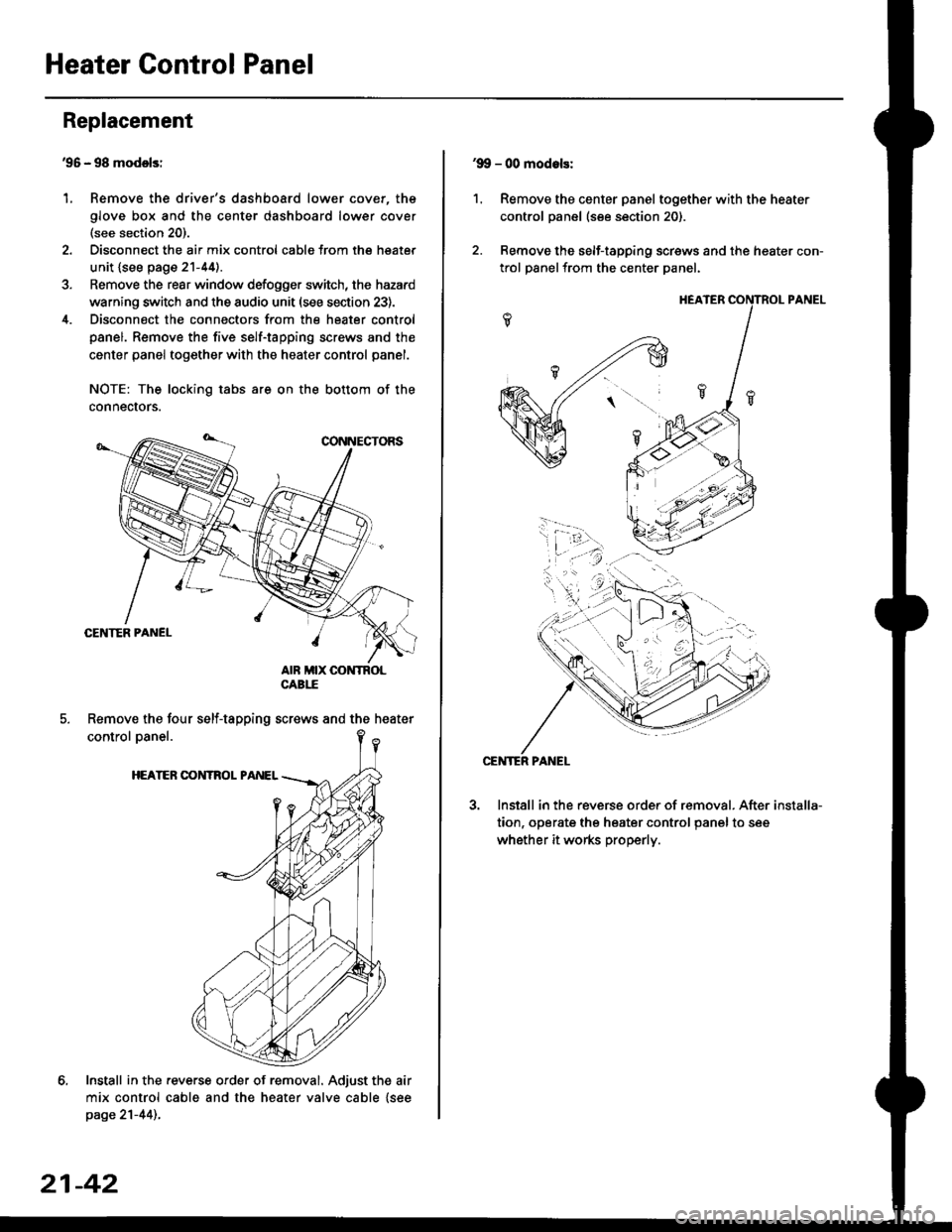
Heater Control Panel
'95 - 98 modolsi
Remove the driver's dashboard lower cover, the
glove box and the center dashboard lower cover(see section 20).
Disconnect the air mix control cabls from the heater
unit {see page 21-44).
Remove the rear window defogger switch, the hazard
warning switch and the audio unit (see section 23).
Disconnect the connectors from the heater control
panel. Remove the five self-tapping screws and the
center panel together with the heater control panel.
NOTE: The locking tabs are on the bottom of the
connecrors.
Install in the .everse order of removal. Adjust the air
mix control cable and the heater valve cable {seepage 21-44)..
Replacement
1.
Remove the four self-tapping screws and the heater
21-42
1.
'9!, - 00 modols:
Remove the center panel together with the heater
control panel (see section 20).
Remove the self-tapping screws and the heater con-
trol panelfrom the center Danel.
Install in the reverse order of removal. After
tion, operate the heater control panel to see
whether it works properly.
installa-
Page 1443 of 2189
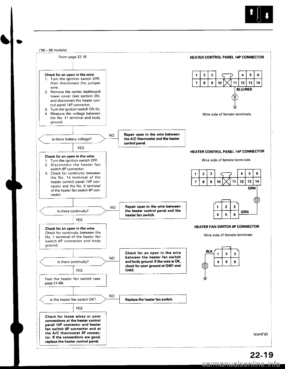
Ftom page 22 18
Check tor an open in the wire:1. Turn the ignition switch OFF,then disconnect the iu mper
2. Remove the center dashboardlower cover lsee section 20),
and disconnect the heater con'
trol panel 14P connector.
3. Turn the ignition switch ON (ll).
4. Measure the voltage betweenthe No. 11 terminal and bodyground.
Repair op6n in the wire bstween
the A/C th€rmostat and th6 hoater
control panel.
Check lor an open in the wire:
1. Turn the ignition switch OFF.2. Disconnect the heater Ian
switch 6P connector,3. Check for continuity between
the No. 14 terminal of theheater control panel 14P con_nector and the No.6 terminalof the heater fan switch 6P con-nector.
Repair open in the wiro betweGnthe heal.r control Panel and theheater fan switch.
Check for an open in thG wire:Check for continuity between theNo. 1 terminal of the heater lanswatch 6P connector and bodYground.
Chock tor an open in tho wir€
between the heater lan switch
and body ground. lf the wire is OK,check for poor ground at G401 sndG402.
ls there continu;ty?
ReDlace the heater tan switch.ls the heater fan switch OK?
Check for loose wiaes or poor
connections at the heater controloanel 14P connoctor and hoetertan 3witch 5P conn€clor and atthe A/C thermostet 3P connec-tor. ll the connections are good,
raplace the heator control Panel.
r'oA - qe m^.lalal
HEATER CONTROL PANEL lilP CONNECTOR
tra6
7II'o lx't1121314
BLU/RED
Wire side of female terminals
HEATER CONTROL PANEL 1'P CONNECTOR
Wire side of female terrninals
HEATER FAN SW]TCH 6P CONNECTOR
Wire side of female terminals
(cont'd)
12;--?45
7I10X'll121314
GRN
123
a56GRN
22-19
Page 1560 of 2189
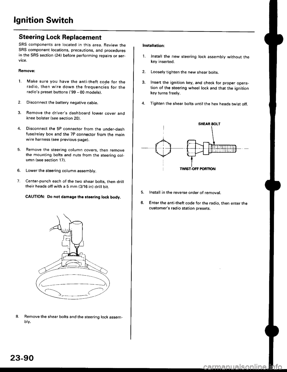
lgnition Switch
Steering Lock Replacement
SRS components are located in this area. Review theSRS component locations. precautions, and procedures
in the SRS section (24) before performing repairs or ser-vtce.
Remove:
LMake sure you have the anti-theft code for theradio, then wire down the frequencies for theradio's preset buttons ('99 - 00 models).
Disconnect the battery negative cable.
Remove the driver's dashboard lower cover andknee bolster (see section 20).
Disconnect the 5P connector from the under-dash
fuse/relay box and the 7P connector from the mainwire harness (see previous page).
Remove the steering column covers, then removethe mounting bolts and nuts from the steering col-umn (see section l7).
Lower the steering column assembly,
Center-punch each of the two shear bolts, then drilltheir heads off with a 5 mm (3/16 in) dritt bit.
CAUTION: Do not damago the steering lock body.
Remove the shear bolts and the steering lock assem,oty.
2.
1.
23-90
Installation:
l. Install the new steering lock assembly without thekey insened.
Loosely tighten the new shear bolts-
Insert the ignition key, and check for proper opera-tion of the steering wheel lock and that the ignitionkey turns freely.
Tighten the shear bolts untilthe hex heads twist off.
TWIST.OFF FORTION
Install in the reverse order of removar.
Enter the anti-theft code for the radio, then enter thecustomer's radio station presets.
sr{€aR SroLT
Page 1661 of 2189
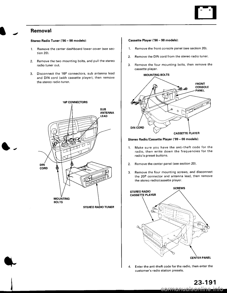
Removal
Stereo Radio Tuner ('96 - 98 modelsl:
3.
1.
2.
Remove the center dashboard lower cover (see sec-
tion 20).
Remove the two mounting bolts, and pullthe stereo
radao tuner out.
Disconnect the 16P connectors, sub antenna lead
and DIN cord (with cassette playerl, then remove
the stereo radio tuner.
16P CONNECTORS
1.
2.
Cassette Player ('96 - 98 modelsl:
Remove the front console panel (see section 20).
Remove the DIN cord from the stereo radio tuner.
Remove the four mounting bolts, then remove the
cassette player.
Stereo Radio/Cassette Player ('99 - 00 modelsl:
1. Make sure you have the anti-theft code for the
radio, then write down the frequencies for the
radio's oreset buttons.
Remove the center panel (see section 20).
Remove the four mounting screws, and disconnect
the 20P connector and antenna lead, then remove
the stereo radio/cassette player.
2.
3.
MOUNTING BOLTS
scREws
Enter the anti-theft code for the radio, then enter the
customer's radio station Presets.
23-191