1997 HONDA CIVIC C101 connector
[x] Cancel search: C101 connectorPage 1500 of 2189
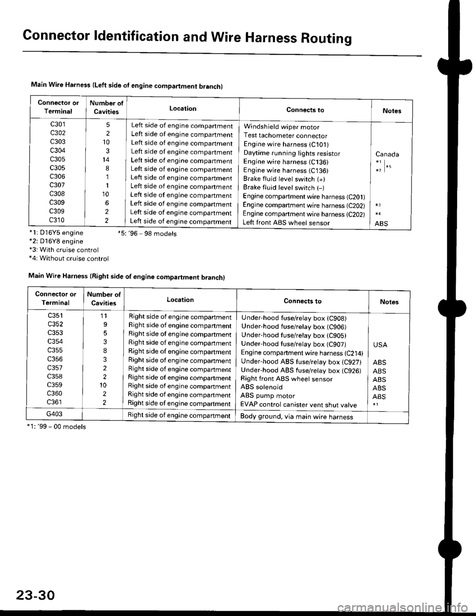
Connector ldentification and Wire Harness Routing
Main Wire Harness lLeft side ot engine compartment branchl
Connector or
Terminal
Number of
CavitiesLocationConnects toNotes
c301
c302
c303
c304
c305
c305
c306
c307
c308
c309
c309
c310
5
2
10
3
14
8
1
I
10
2
2
Left side of engine compartment
Left side of engine compartment
Left side of engine companment
Left side of engine compartment
Left side of engine compartment
Left side of engine compartment
Left side ot engine companment
Left side of engine companment
Left side of engine compartment
Left side of engine companment
Left side of engine companment
Left side of engine companment
Windsh ield wiper motor
Test tachometer connector
Engine wire harness (C101)
Daytime running lights resistor
Engine wire harness (C136)
Engine wire harness (C136)
Brake fluid level switch (+)
Brake fluid level switch (-)
Engine compartment wire harness (C201)
Engine companment wire harness (C202)
Engine compartment wire harness (C202)
Left front ABS wheel sensor
Canada
;|.'
ABS*lr D'16Y5 engine *5:'96 9g models*2: D16Y8 engine*3: With cruise control*4r Without cruise control
*1: '99 - 00 models
Main Wire Harness (Right side of engine compartment branch)
Connector or
Terminal
Number of
CavitiesLocationConnects toNotes
c353
c354
c355
c356
c357
c359
c360
11
3
I
3
2
2'10
2
2
Right side of engine compartment
Right side of engine companment
Right side of engine companment
Right side of engine compartment
Right side of engine compartment
Right side of engine companment
Right side of engine compartment
Right side of engine compartmentRight side of engine compartment
Right side of engine compartment
Right side of engine compartment
Under-hood fuse/relay box (CgoB)
Under-hood fuse/relay box (C906)
Underhood fuse/retay box (C905)
Under-hood tuse/relay box (C907)
Engine companment wire harness {C214)Under-hood ABS fuse/relay box {C927)Under-hood ABS fuse/retay box (C926)
Right front ABS wheel sensor
ABS solenoid
ABS pump motor
EVAP control canister vent shut valve
USA
ABS
ABS
ABS
ABS
ABS
G403Right side of engine compartmentBody ground, via main wire harness
23-30
Page 1871 of 2189
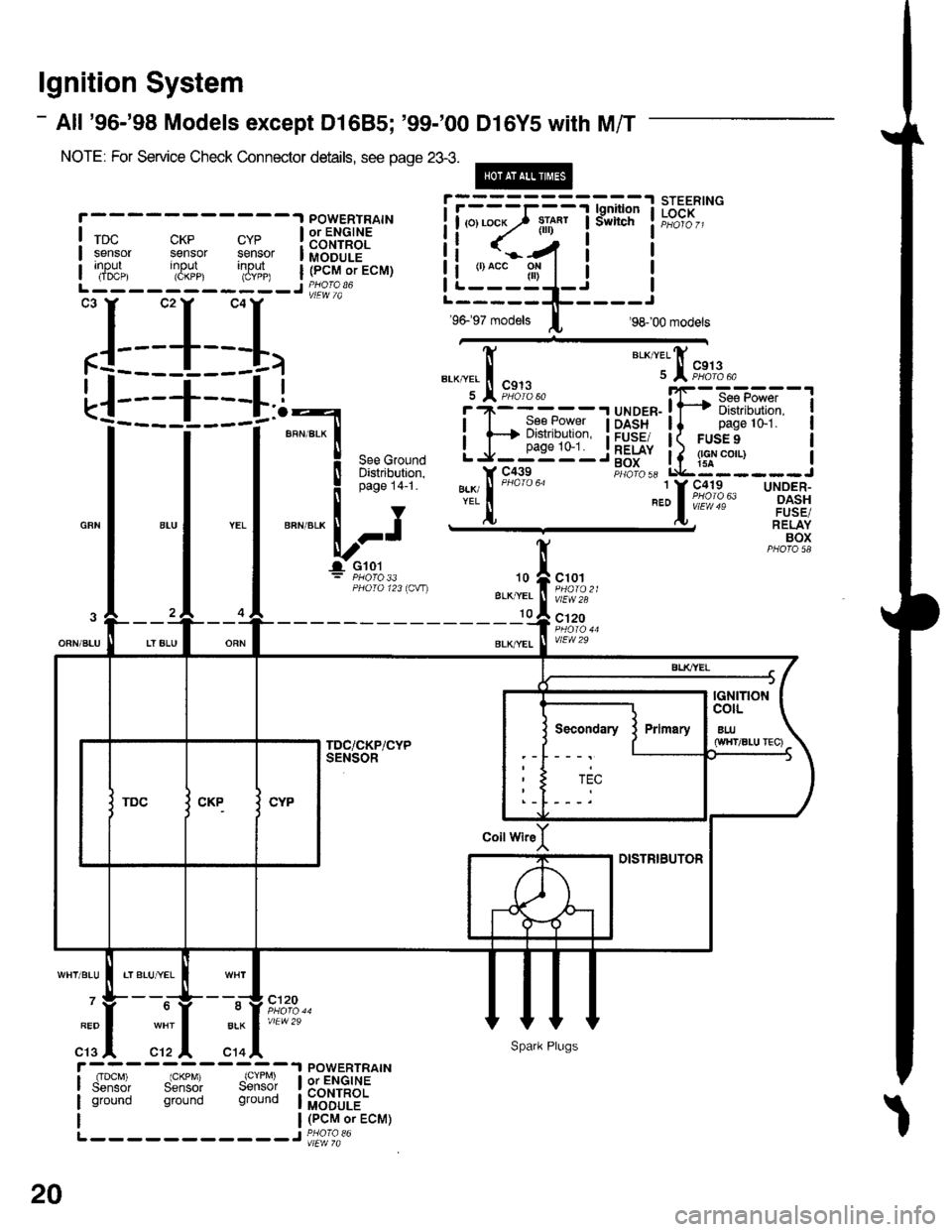
lgnition System
- All '96-'98 Models except Dl685; '99-'00 Dl6Y5 with M/T
NOTE: For Service Check Connector details, see page 23-3.
@
CKP CYPsensor sensorinput input(CKPP) (CYPP)
X,*.,
rDcsensorInpur(IDCP)
POWERTRAINor ENGINECONTROLMODULE(PCM or ECM)
POWERTRAINor ENGINECONTROLMODULE(PCM or ECM)
xr*"
BLKI/EL
I
I
BLK/YEL
I See Power
H Distribution,
J__99'�"'_
I
I
I
I
I
I
UNOER-OASHFUSE/RELAYBOX
"a*,telfi
u I """%t'3.
,rrrr.iFiFx".-,''ril'fi :T-DASH ll pagelo-1.FUSE/ I( FUSE 9
F.itl, Lq::---
".:lo63
10
BLK,YEL
10
c101
vlEW28
c'120
vlEW29
BLK
c14
c120
vlEW29
rIDcM) IGKPM) (CYPM)Sensor Sensor Sensolground ground ground
L-- - - -- -----J PHora 36
L-----------J
:L_1__I,
! iii:?ifq"l
I
**:'
*-"*,t";'
= PHO|O 33PHOTO 123ICW)
Secondary
ti <..-/4 i t
iLi:"_gl_i iL-----1!-----r
96- 97 models I 98- 00 modets
20
Spark Plugs
Page 1872 of 2189
, r -.-- .l TBANSMTSS|ON
I igF"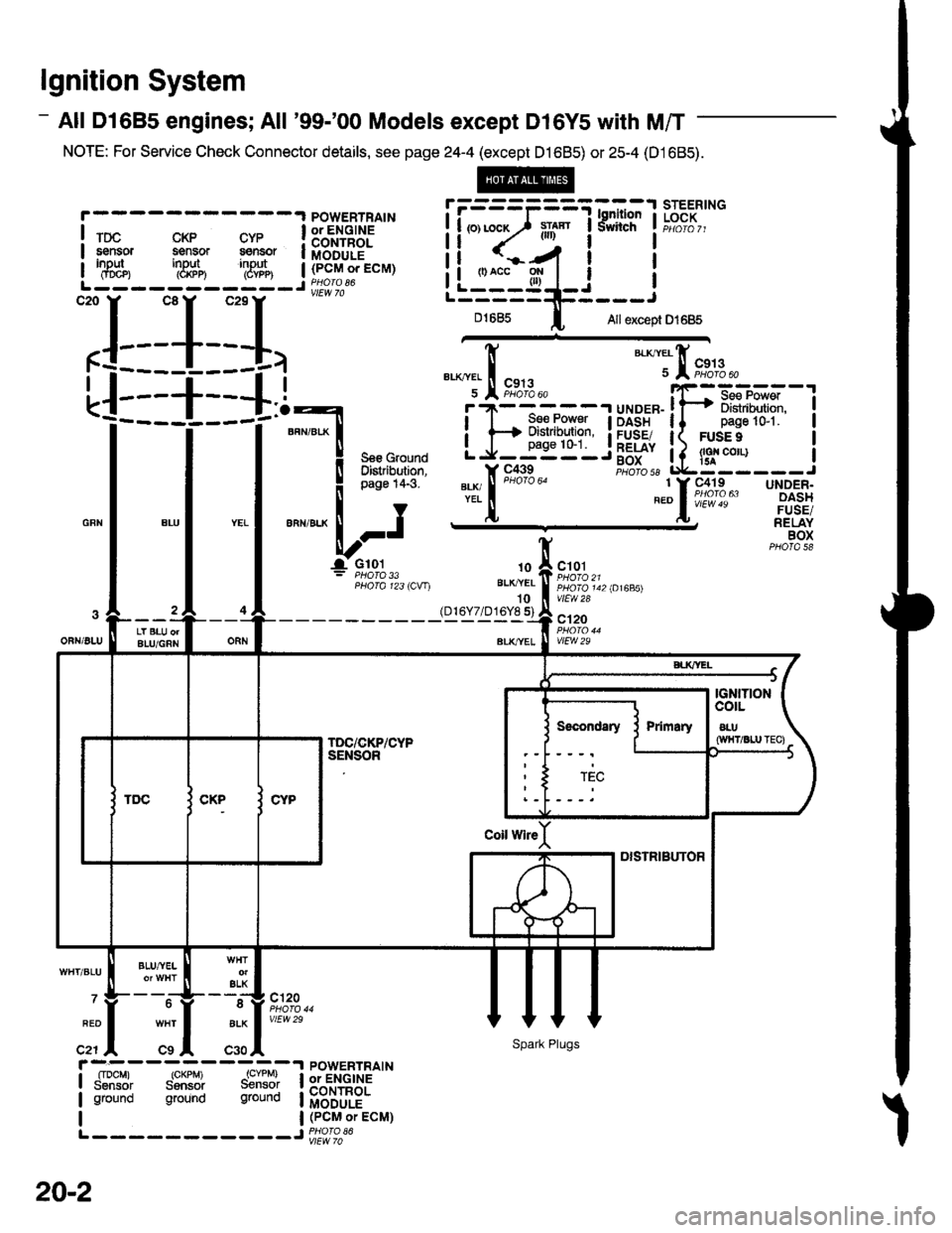
lgnition System
- All Dl685 engines; All '99-'00 Models except Dl6Y5 with M/T
NOTE: For Service Check Connector details, see page 24-4 (except D1685) or 25-4 (D1685).
STEERINGLOCKPOWERTRAIN
lm- sii.- s*- iffffiEgr
I '8f", '3#n '3#n | (Pcn' or EcM)
L------ -----J Wro 86
',L_I__J,
!l---+--l !
'i---
j----i'
fl '","?siii,xl
I I I
i*n"'."
-"1 "-l '-l *"-^lr";J
I I I ='i.{i31i",,-
All except D1685D1685
gLK.Yer t
u l9f#'
fi
"*1,[
F,*';.,
!'T-f*-'i"i! {F+ Distdbution,
LJ_gg'n'_
i.x,r
9'x*"
-.t
iF--Hs-,mT-l
ll pase lGi. I
l( FUsEe I
!Lig::___J
.I UNDER-I DASH
a FUSE/
! RELAY- BOX
1 Y C419 UNDER-^,ol',lill,l?"u' rlir?IA) RELAYBOX
.t0
BLKI/EL
10(D16Y7/D16Y8 s)
c101
PHO|O 142 lA1685)vlEw 2a
c120
vtEw 29OFN/ALULT BLU orALU/GRN
BLU,^VEL
c120
vtEw 29
ELKWHT/BLU
7
FED
c21c9
ALK
c30
;;--;;---o;;;lSensor Sonsor Sensor I
POWERTRAINor ENGINECONTROLMODULE(PCM or ECM)
ground ground gtound
L ------ -----J PHoro 36
Sec!l|dary
Sparh Plugs
20-2
Page 2123 of 2189
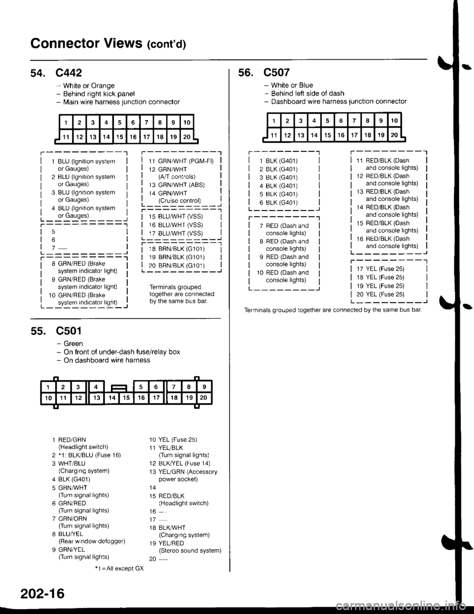
Connector Views (cont'd)
54. c442
- White or Orange- Behind right kick panel- l\,lain wire harness junction connector
r---------Tr---------"1
1 BLU (lgnition systemor Gauges)
2 BLU (lgnition syslemor Gauges)
3 BLU (lgnition systemor Gauges)
4 BLU (lgnition system
L_ or causes)L_-:-:::'-'�____Jt-----------1
11 GRN/WHT (PGM-FD
12 GRN/WHT(A/T controls)
13 GRNMHT (ABS)
14 GRNMHT
L_ lc,r'." .oIr"D_ _ _.jr----------_l
5
6
7L---------JT----------l8 GRN/RED (Brake
system indicator light)
9 GRN/RED (Brake
system indicator light)
10 GRN/RED (Brake
_ system indicator ligh0 -..1
| 15 BLUMHT (vSS) |I 16 BLUMHT (VSS) I
L T?_BLUSTrySS)--..]
l--------- - -l
| 18 BFN/BLK (G101) I| 19 BBN/BLK (G101) || 20 BRN/BLK (c101) |L---------J
Terminals groupedtogether are connectedby the same bus bar.
55. C501
- Green- On tront of under-dash tuse/relay box- On dashboard wire harness
l RED/GFN(Headlight switch)
2 *1 : BLKBLU (Fuse 16)
3 WHT/BLU(Charging systern)
4 BLK (G401)
5 GRNMHT(Turn signal lights)
6 GRN/RED(Turn signal lights)
7 GRN/ORN(Turn signal lights)
8 8LU/YEL(Rear w ndow delogger)
9 GFN/YEL(Turn signal lights)
'10 YEL (Fuse 25)
11 YEL/BLK(Turn signal lights)
12 BLKTYEL (Fuse 14)
13 YEUGRN (Accessorypower socket)
15 RED/BLK(Headlight switch)
1B BLK/WHT(Charglng system)
19 YEL/RED(Stereo sound system)
20
202-16
-1 =All e),cept GX
s6. c507
- White or Blue- Behind left side oJ dash- Dashboard wire harness junction connector
r --------'lT---------l
7 BED (Dash andconsole lights)
B BED (Dash andconsole lights)
I RED (Dash andconsole lights)
10 RFD (Dash andconsole lights)
11 RED/BLK (Dash
and console lights)
12 RED/8LK (Dash
and console lights)
13 RED/BLK {Dashand console lights)
14 RED/BLK (Dash
and console lights)
15 RED/BLK (Dash
and console lights)
16 RED/BLK (Dash
and console lights)L--------J
T--------T
L---_---_J
1 BLK (G401)
2 BLK (G401)
3 8LK {G401)4 8LK (G401)
5 BLK (G401)
6 8LK (G401)L________J
T--------"1
17 YEL (Fuse 25)
18 YEL (Fuse 25)
19 YEL (Fuse 25)
20 YEL (Fuse 25)L--------J
Term nals grouped together are connected by the same bus bat
Page 2143 of 2189
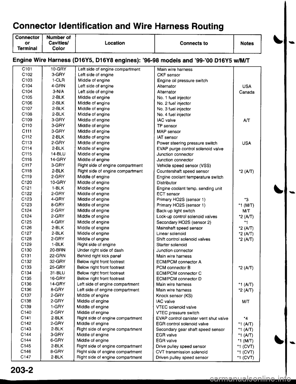
Connector ldentification and Wire Harness Routing
Connector
or
Terminal
Number ot
Cavities/
Golor
LocationConnects toNotes
Engine Wire Harness (Dl6Y5, D16Y8 engines): '96-98 models and '99;00 D16Y5 dM/T
c101
c102
c 103
c104
Q104
c105
c106
c107
cl 08
cl09
cl10
c1l1
cl'12
c113
c114
c'115
c116
c'117
c 118
c119
c120
c121
c122
c123
c123
c124
Q124
c125
c 126
c127
c128
c129
c130
c131
cl32
c 134
c135
c136
c137
c138
c139
c'140
c141
c142
c143
c144
c'|44
c145
c146
c147
1O-GRY
3.GRY
1-CLR
4-GRN
3-N/A
2-BLK
2-BLK
2-BLK
2-BLK
3-GRY
3-GRY
3-GRY
2.BLK
2.GRY
2-BLK
14-BLU
14-GRY
3.GRY
2-BLK
2-GRY
1O-GRY
1.BLK
2.GRY
4-GRY
8-GRY
2-GRY
2.GRY
4-GRY
2.BLK
2.BLK
2-GRY
1.BLK
2O.BRN
22.GRN
32.GRY
25.GRY
31-BLU
16.GRY
14-GRY
8.GRY
2-GFIY
2.GRY
1-GRY
2-GRY
2-BLK
2-GRY
2.BLK
3-GRY
6-GRY
2.BLK
8-GRY
2-BLK
Left side of engine compartment
Left side of engine
Middle of engineI att .i.la ^f an^i^6
Left side ot engine
Middle of engine
Middle of engine
Middle of engine
Middle of engine
Middle of engine
[,liddle of engine
Middle ot engine
Middle ot engine
Middle of engine
Middle of engine
Middle of engine
l\,liddle of engine
Right side of engine compartment
Right side of engine compartment
Middle ot engine
Middle of engine
Middle of engine
Middle of engine
l\,liddle of engine
Nliddle of engine
Middle ot engine
Middle of engine
Middle ot engine
Middle of engine
Middle of engine
Nliddle of engine
Right side of engine
Under right side of dash
Behind right kick panel
Below right front footrest
Below right front footrest
Below right front footrest
Below right front tootrest
Left side ot engine compartment
Left side of engine compartment
Middle of engine
liliddle ot engine
Middle of engine
Nriddle ol engine
Right side of engine compartment
Middle ol engine
Right side of engine compartment
Middle of engine
N,liddle of engine
Right side of engine compartment
Right side of engine compartment
Bight side of engine compartment
Main wire harness
CKF sensor
Engine oil pressure switch
Alternator
Alternator
No. 1 fuel injector
No. 2 fuel injector
No. 3 fuel injector
No.4 fuel injector
IAC valve
TP sensor
MAP sensor
IAT sensor
Power steering pressure switch
EVAP purge control sol€noid valve
Junction connector
Junction connector
Vehicle speed sensor (VSS)
Countershatt speed sensor
Engine coolant temperature switch
Distributor
Engine coolant temp. sending unit
ECT sensor
Primary HO2S (sensor '1)
Primary HO2S (sensor '1)
Back-up light switch
Lock-up control solenoid valves
Secondary HO2S (sensor 2)
lvlainshafl speed sensor
Lanear solenoid
Shift control solenoid valves
Starter solenoid
Junction connector
Main wire harness
ECM/PCM connector A
PCM connector B
ECM/PCNI connector C
ECM/PCl\,,| connector D
Main wire harness
Maln wire harness
Knock sensor (KS)
IAC valve
VTEC solenoid valve
VTEC pressure switch
EVAP control canister vent shut valv€
EGR control solenoid valve
Secondary gear shatt speed sensor
EGR valve
EGR valve
Drive pulley speed sensor
CVT transmission solenoid
Driven pulley speed sensor
USA
Canada
AlT
USA
'2( tr\
'3
-1 (M/r)
t\4/T'2 (Anl'1
'2 (An)'2 (Nr)'2 (AtT)
'2 (Atr)
-1 (An)-2( fi|
M/T
.1 (Arr).1 (A,T)"1 (A/r)-1 (M/r).1 (CVT),1 (cw)'1 (CVT)
203-2
Page 2147 of 2189
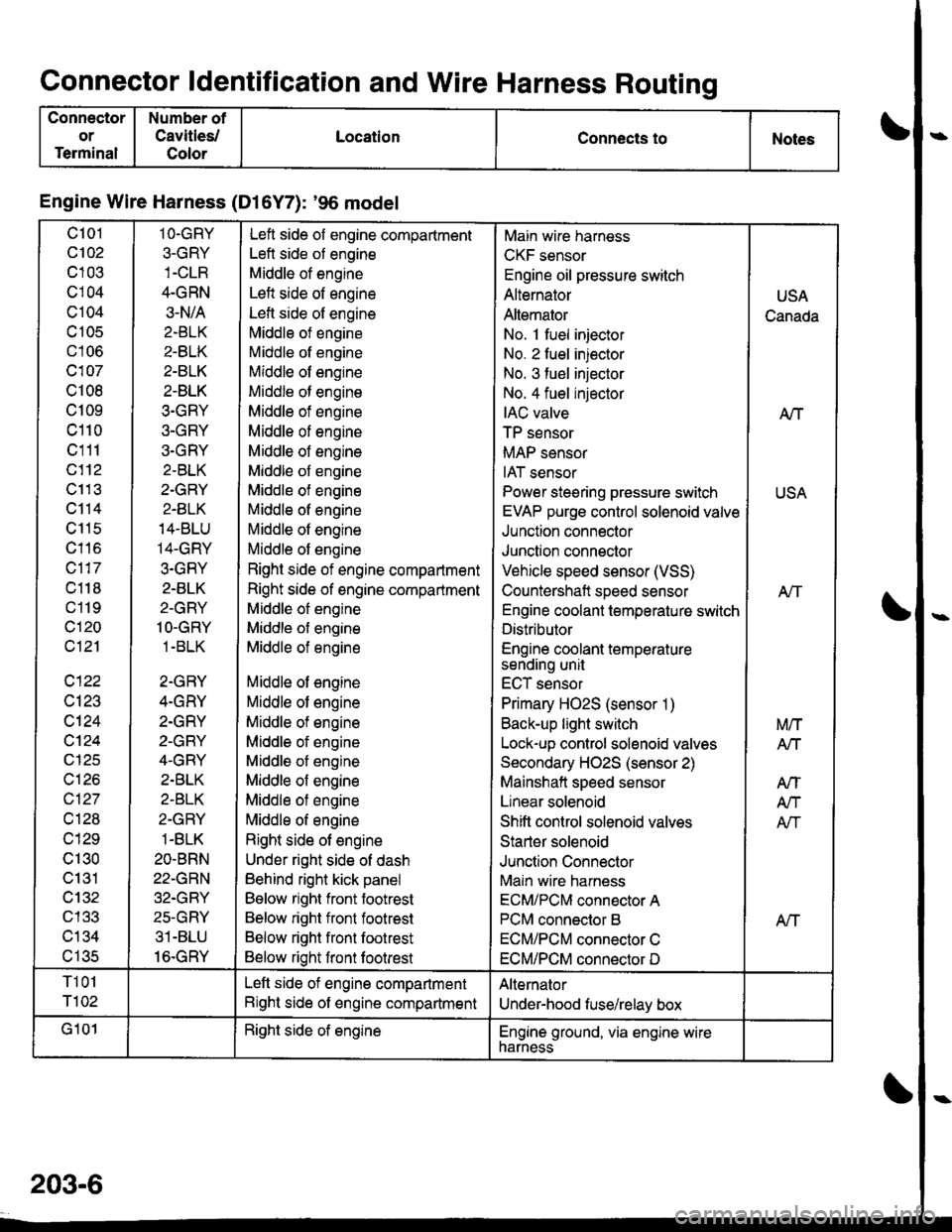
Connector ldentification and Wire Harness Routing
Connector
or
Terminal
Number of
Cavities/
Color
LocationConnects toNotes
Engine Wire Harness (Dl6Y7): '96 model
c101
c102
c103
cl04
c104
c 105
c106
c107
c108
c109
c110
c111
c112
c11 3
c114
c115
c116
c117
c118
c119
c120
c121
c122
c123
c124
cl24
c125
c126
c127
cl28
c129
c130
c131
cl32nl2?
c134al eR
1O.GRY
3-GRY
4.GRN
3-N/A
2.BLK
2-BLK
2-BLK
2-BLK
3.GRY
3-GRY
3.GRY
2-BLK
2.GRY
2-BLK
14-BLU
14-GRY
3.GRY
2.BLK
2-GRY
1O-GRY
1 -BLK
2-GRY
4.GRY
2.GRY
2-GRY
4-GRY
2.BLK
2-BLK
2-GRY
1-BLK
2O-BRN
22-GRN
32.GRY
25-GRY
31-BLU
16.GRY
Left side of engine compartment
Left side of engine
Middle of engine
Left side of engine
Lefl side of engine
Middle of engine
Middle of engine
Middle of engine
Middle of engine
Middle of engine
Middle of engine
Middle of engine
Middle of engine
Middle of engine
Middle of engine
Middle of engine
Middle of engine
Right side of engine compartment
Right side of engine compartment
Middle of engine
Middle of engine
Middle of engine
Middle of engine
Middle of engine
Middle of engine
Middle of engine
Middle of engine
Middle of engine
Middle of engine
Middle of engine
Right side of engine
Under right side of dash
Behind right kick panel
Below right front footrest
Below right front footrest
Below right front footrest
Below right front footrest
Main wire harness
CKF sensor
Engine oil pressure switch
Alternator
Altemator
No. 1 fuel injector
No. 2 fuel injector
No. 3 fuel injector
No. 4 fuel injector
IAC valve
TP sensor
MAP sensor
IAT sensor
Power steering pressure switch
EVAP purge control solenoid valve
Junction connector
Junction connector
Vehicle speed sensor (VSS)
Countershaft speed sensor
Engine coolant temperature switch
Distributor
Engine coolant temperaturesending unit
ECT sensor
Primary HO2S (sensor 1)
Back-up light switch
Lock-up control solenoid valves
Secondary HO2S (sensor 2)
Mainshaft speed sensor
Linear solenoid
Shift control solenoid valves
Starter solenoid
Junction Connector
Main wire harness
ECM/PCM connector A
PCM connector B
ECM/PCM connector C
ECM/PCM connector D
USA
Canada
A/T
USA
Atf
Aff
M/T
Arl
AtT
A/T
Afi
T101
T102
Left side of engine compartment
Right side of engine compartment
Alternator
Under-hood fuse/relay box
G101Right side of englneEngine ground, via engine wirenarness
203-6
Page 2149 of 2189
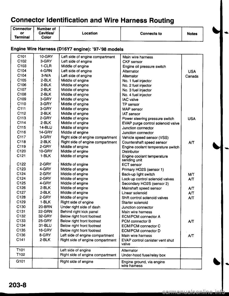
Connector ldentification and Wire Harness Routing
Connector
or
Terminal
Number of
Cavities/
Color
LocationConnects toNoles
Engine Wire Harness (Dl6Y7 engine): '97-'98 models
c101
c102
c103
c104
c104
c105
c106
c107
c108
c109
c110
c111
c113
c114
c115
c116
c118
c119
c'120
c121
c122
c124
c124
c125
c126
c127
c128
c129
cl30
c131
c132
c133
c134
c135
\, | 'tO
c141
1O-GRY
3-GRY
1.CLR
4.GRN
3.N/A
2-BLK
2-BLK
2-BLK
2-BLK
3.GRY
3-GRY
3-GRY
2-BLK
2.GRY
2-BLK
14.BLU
14.GRY
3.GRY
2-BLK
2-GRY
lO.GRY
1-BLK
2-GRY
4.GRY
2.GRY
2-GRY
4.GRY
2.BLK
2.BLK
2-GRY
1-BLK
2O-BRN
22-GRN
32-GRY
25.GRY
31-BLU
16.GRY
8-GRY
2-BLK
Lefl side of engine compartment
Lett side of engine
Middle of engine
Left side of engine
Lefl side of engine
Middle of engine
Middle of engine
Middle of engine
Middle of engine
Middle of engine
Middle of engine
Middle of engine
Middle of engine
Middle of engine
Middle of engine
Middle of engine
Middle of engine
Right side of engine compartment
Right side of ongine compartmont
Middle of engine
Middle of engine
Middle of engine
Middle of engine
Middle of engine
Middle of engine
Middle of engine
Middl€ of engine
Middle of engine
Middle of engine
Middle of engine
Right side of engine
Under right sido of dash
Behind right kick panel
Below right front footrest
Below right front footrest
Below right front footrest
Below right front footrest
Left side of engine compartment
Right side of engine compartmsnt
Main wire hamess
CKF sensor
Engine oil pressure switch
Alternator
Altemator
No. 1 fuel injector
No. 2 fuel iniector
No. 3 fuel iniector
No. 4 fuel injector
IAC valve
TP sensor
MAP sensor
IAT sensor
Power steering pressur€ switch
EVAP purge control solenoid valve
Junction connector
Junction connector
Vehicle speed sensor (VSS)
Countershaft speed sensor
Engine coolant temperature switch
Distributor
Engine coolant temperatu resenorng unI
ECT sensor
Primary HO2S (sensor 1)
Back-up light switch
Lock-up control solenoid valves
Secondary HO2S (sensor 2)
Mainshaft speed sensor
Linear solenoid
Shift conirol solenoid valves
Starter solenoid
Junclion connector
Main wire harness
ECM/PCM connector A
PCM connector B
ECM/PCM connector C
ECM/PCM connsctor D
Main wire harness
EVAP control canister vent shutVAIVE
USA
Canada
USA
Nf
A/T
M/T
A/T
Atl
An
AIT
NT
T101
T102
Left side of engine
Right side of engine compartment
Altemator
Under-hood fuse/relay box
G101Right side of engineEngine ground, via enginewtre narness
203-8