Page 924 of 2189
From page 14 246
Moasure ATP S Voltage:
1. Shift to E Position2. Measure the voltage between
the A8 and 413 or 426 termi
nals,
Bepair open in the wir€ between
the A8 t€rminal and the A/T gear
position switch.
Measure ATP L Vohage:
1. Shift to E Position2. Measure the voltage between
the A7 and A13 or 426 termi-
nals.
Repair open in the wire between
the A7 terminal and the A/T geal
Dosition switch
Chock tor loose TCM connectors.
lf necessary, substitute a l(nown-
good TCM and recheck,
TCM CONNECTOR A l26p)
Wire side of female terminals
14-247
Page 926 of 2189

Troubleshooting Flowchart - Manifold
NOTE: Record all freeze data before you troubleshoot
Absolute Pressure {MAPI Sensor
TCM CONNECTORS
Wire side of female terminals
PG.iblo Cau3€
. Dkconnoctod manilold .bsoluto
ore33urc IMAP) sensor connoc'
lor. Short or opcn in MAP s.nsor
MAP sen3or
. OBD ll Scan Tool indicates Code
P1793,. self-diagno3b E indicato. light
indicat€s Code 12.
Chock tor Another Cod€ or MIL
Blinking:1. Turn the ignition switch ON (ll).
2. Check whether the OBD ll scan
tool indicates another code or
the Mal{unction Indicator LamP(MlL) blinks (sse section 11).
Does the OBD llscan tool indicate
another code or isthe lVlL blink-
in9?
Measure VREF voltage:
1. Turn the ignition switch OFF.
2. Disconnect the A (26P) and B
(22P) connectors trom the
TCM.3. Turn the ignition switch ON (ll).
4, Measure the voltage between
the B2O and A13 or A26 termr
nals.
R€pair opon or 3hort in the wire
botwoan the 820 t€.minal and
the EcM.lsthere aPprox.5 V?
Msasure MAP IPB) volt.ge:
Measure the voltage betlveen the
82 and A13 or 426 terminals.
Repair opon ot shorl in the wiro
betwesn the 82 torminal end th€
MAP sensol.ls there approx. 3 V?
Check for loo3e TCM conn€stors.
lf nec*sarY, sub3titute a known'
good TCM and rechock.
WHT/RED
14-249
Page 930 of 2189

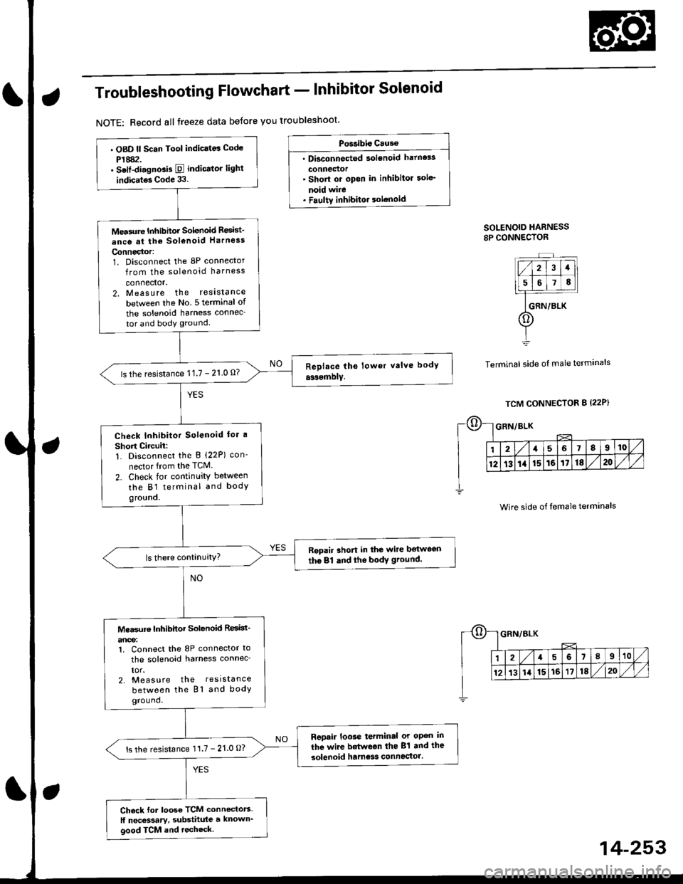
Troubleshooting Flowchart - Inhibitor Solenoid
NOTE: Record all treeze data betore you troubleshoot
Po$ibls Cause
. Dbconnected solenoid hatness
connedor' Short or opon in inhibitor sole'
noid wire. Faultv inhibitor solenoid
SOLENOID HARNESS8P CONNECTOR
Terminal side of male terminals
. OBD ll Scan Tool indic.td Code
P1882.. Selt-di.gnGis E indicator lighl
indic.tos Code 33.
Mea3ure Inhibhor Solenoid Resid-
ance at the sol€noid Harness
Connector:1. Disconnect the 8P connector
from the solenoid harness
connector.2. Measure the reslstance
betlveen the No 5 terminal of
the solenoid harness connec-
tor and body ground.
ls the resistance 11.7 - 21 0 0?
Check Inhibitor Solenoid lor a
Short Circuii:1. Disconnect the B (22P) con-
nector from the TCM.
2. Check for continuity between
the B1 terminal and bodygro!no.
Repair rhort in the wire ltetwegn
the 81 dnd the bodY ground.
Mea$rr€ Inhibitor Solenoid ResBt'
anoe:1. Connect the 8P connector to
the solenoid harness connec_
IOr.2. Measure the resistance
between the Bl and bodyground.
Reoair loose terminal or open in
the wire betwean the 81 and the
solenoid hame3s connector'ls the resistance 11.7 - 21.0 O?
Ch6ck for loose TCM connectors.
ll necessary, substhule a known_good TCM and techeck.
Wire side of female terminals
14-253
Page 934 of 2189

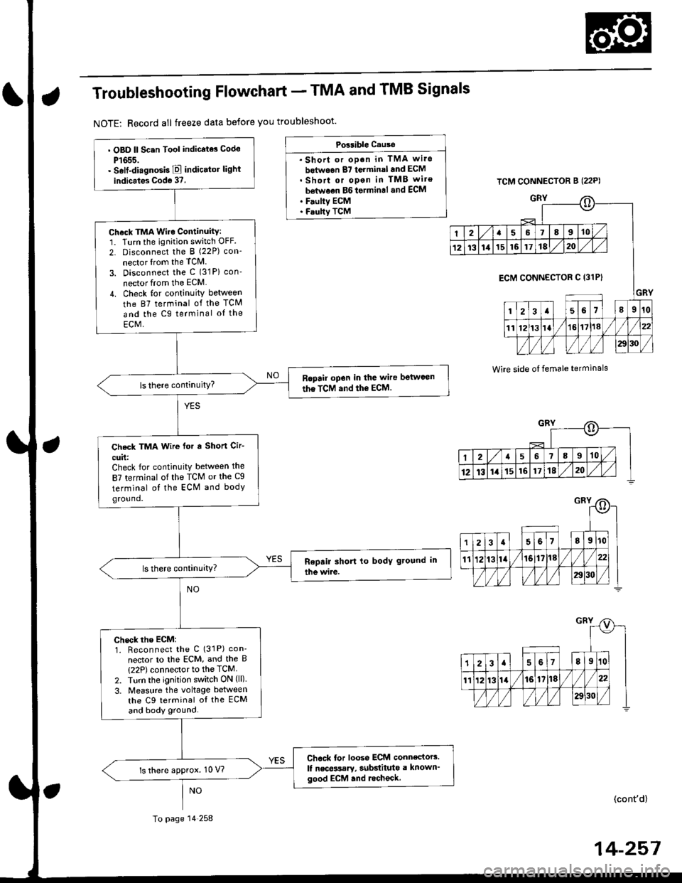
Troubleshooting Flowchart - TMA and TMB Signals
NOTE: Record all freeze data before you troubleshoot'
Possible Cause
. Shorl or op.n in TMA wi.o
botwo6n 87 terminal and ECM. Short or open in TMB wiro
bdtwoon BG to.min.l .nd ECM. F.ulty ECM. Faulty TCM
TCM CONNECTOR B (22P)
GRY
Wire side oI temale terminals
o
I2a58910
1213111516171820
GRY
ECM CONNECTOR C 13lPI
123a56l89r0
1112t3la1618//
29130 /
::)
I2a568910
12t3141516171820
. OBD ll Scsn Tool indicate3 Codo
P1655.. Self-diagnosb E indicator light
indicales Cod6 37.
Check TMA Wire Continuity:1. Turn the ignition switch OFF.
2- Disconnect the I (22P) con-
nector lrom the TCM
3. Disconnect the c (31P) con'
nector from the ECM
4. Check for continuity between
the 87 terminal of the TCM
and the Cg terminal oI the
ECM,
Ropail open in the wire betwcen
the TCM and the ECM.
Check TMA Wir€ for a Short Cir-
cuit:Check for continuity between the
87 terminal of the TCM or the Cg
terminal ol the ECM and bodyground.
check rhe EcM:1. Reconnect the C (31P) con'
nector to lhe ECM, and the B(22P) connector to the TCM
2. Turn the ignition switch ON (ll).
3. Measure the voltage between
the C9 terminal oI the ECM
and body ground.
Chock tor loose ECM connectors.
lf nscossary, subdituta a known'good ECM .nd lecheck.ls there approx. 10 V?
To page 14 258
(cont'd)
14-257
Page 939 of 2189

Electrical Troubleshooting ('96 - 98 Modelsl
Troubleshooting Flowchart - Pl Indicator Light Does Not Gome On
TCM CONNECTOR A {26P)
BLI
l-I
123a589101t12nl
1a151617202325rt
o
8LK
Wire side of female terminals
The E Indicator light does notcome on when the ignition switchis tirst turned ON {ll). {lt shouldcome on for aboul two s€conds,)
Chock the Service Check Connec-lot:Make sure the special tool (SCS
Service Connector) is not connected to the seryice check connector,
ls the special tool (SCS ServiceConnector) connected to the ser-vice check connector?
Disconn€ct the sDecial tool fromthe seruice check connector andrecheck.
Check the E Indicator Light:Shift to [5] oosition.
Check fo. loose TCM connectors.lf neceasary, substitute a known-good TCM .nd rochock.
Does the E indicator lightcome on?
Ch€ck th6 Ground Circuit:1. Turn the ignition switch OFF.2. Disconnect the A 126P) con-nector from the TCM.3. Check tor continuity betweenthe A13 terminal and bodyground and the 426 terminaland body ground.
.Repair open in the wiresbetwoon lhe A13 or A26 termi-nel3 and G101.. Repai. poor ground {G1011.
To page 14-263
14-262
>.
Page 942 of 2189

Electrical Troubleshooting ('99 - 00 Models)
Troubleshooting Flowchart - A/T Gear Position Switch (Short)
NOTE: Record all freeze data before you troubleshoot.
Po3sible Cause
. Short in A/T gear po3ition 3witch
. F.ulty A/T ge6r Position switch
NOTE: Code P1705(5) is caused when
the PCM received two gear Positioninputs at the same time.
PCM CONNECTORS
LGl (BRN/8LKI LG2 (BRN/8LKI
Wire side of female terminals
(cont'd)
14-265
B t25Pt llO(16P1
. oBD ll scln lool indicats code
P't705.. Self-diagnosb E indicator light
blinks fivetim€s.
Obseive tho A/T Gear Polition
lndicetor:1. Turn the ignition switch ON (ll).
2. Observe the A,/T gear positaon
indicator, and shift oach Posi-tion separately.
Tho ry3t6m is OK at this tims.
Check th€ wiro hsrno!! tor
damage.
Does any indicator stay on
when the shift lever is not an
that position?
M.Furo ATP R Vohtge:1. Shift to all positions other than
E.2. Measure the voltage between
the D6 and 820 or 822 termi'
nals,
Chock for lhort in tho wit€
betwe€n the D6 telminal and thg
A/T ge.r position 3witch or A/T
gear po3ition indicttoi, !nd
chcck for open in the witgs
botwo€n the 820 lnd 822 tetmi_n.ls and body g.ound (G1011. F
wiro3 ere OK, check tor loo3o ter'
minal fit in the PrCM connoctors.ll n6c€3sary, 3ubstitute a known-good PCM and rochock.
ls there approx. 10 V?
To page 14 266
Page 944 of 2189

M6asure ATP S Voliag€:1. Shift to all positions other
than E.2. Measure the voltage between
the D13 and 820 or 822 termi
nals.
Check for short in the wire
between the D13 terminal and
the A/T gear position lwitch orA/T goar position indicator. Itwir6s are OK, check lor loose l€r-
minal fit in the PCM connectors.ll nec*3arv, substitute a known'good PCM and r6check.
ls there approx. '10 V?
Measure ATP L Voltage:1. Shi{t to all positions other
than E.2. Measure the voltage between
the A22 and 820 or 822 termi-nals.
Check lor sho.t in ihe wire
betwgon the A22 terminal and
th. A/T geat position switch or
A/T gear position indicator. It
wires are OK, ch€ck for 10036 ter-minal fit in the PCM connectors.lf n6cessery, substitute a known_good PCM and recheck.
ls there approx- 10 V?
Check tor loos€ terminalfit in the
PCM connectors, It nec6s3arY,
substitute a known-good PCM
and rech6ck.
From page 14-266
B t2sP)
LG1{BRN/BLKI
t32Pl
PCM CONNECTORS
Wire side of Iemale terminals
PCM CONNECTORS
D (16P1
ATP S {LT GRN/RED)
LG2 (BRN/BLKI
B t25Pl
Page 947 of 2189
Electrical Troubleshooting {'99 - 00 Models}
Troubleshooting Flowchart - A/T Gear Position Switch (Openl (cont'dl
Bepair opon in the wiro bgtw€enlho A22 torminal and the A/Tgoar poihion lwitch.
PCM CONNECTORS
B (25P1
LGT (BFN/ALK}
PCM CONNECTOR B I25PI
12.15 / 7I
9't0l1Br1/l/41it8
ll lLG2
o) (o)
IBRN/BLKI
Wire side of female terminals
From page 14-8-269
Msasuro ATP L Voftage:1. Shiftto E position.
2. Measure the voltage betweenthe A22 and 820 or 822 termi-nals,
Check LG Wiro for .n Open Cir-cuit:']� Turn the ignition switch OFF.2. Check lor continuity betweenthe 820 t€rminal and bodyground, and between the 822terminal and body ground.
Ropai' op.n in the wir€a botw.€nthe 820 rnd 822 toJminals .ndbody ground, and .opsi. poolground (Gl01l.
Check tor loose te.minal frt in th6PCM conn€ctors, lf n€cessary, sub-stitut€ a knowo-good PCM anda6check,
Wire side of female terminals
14-270