Page 1731 of 2189

I
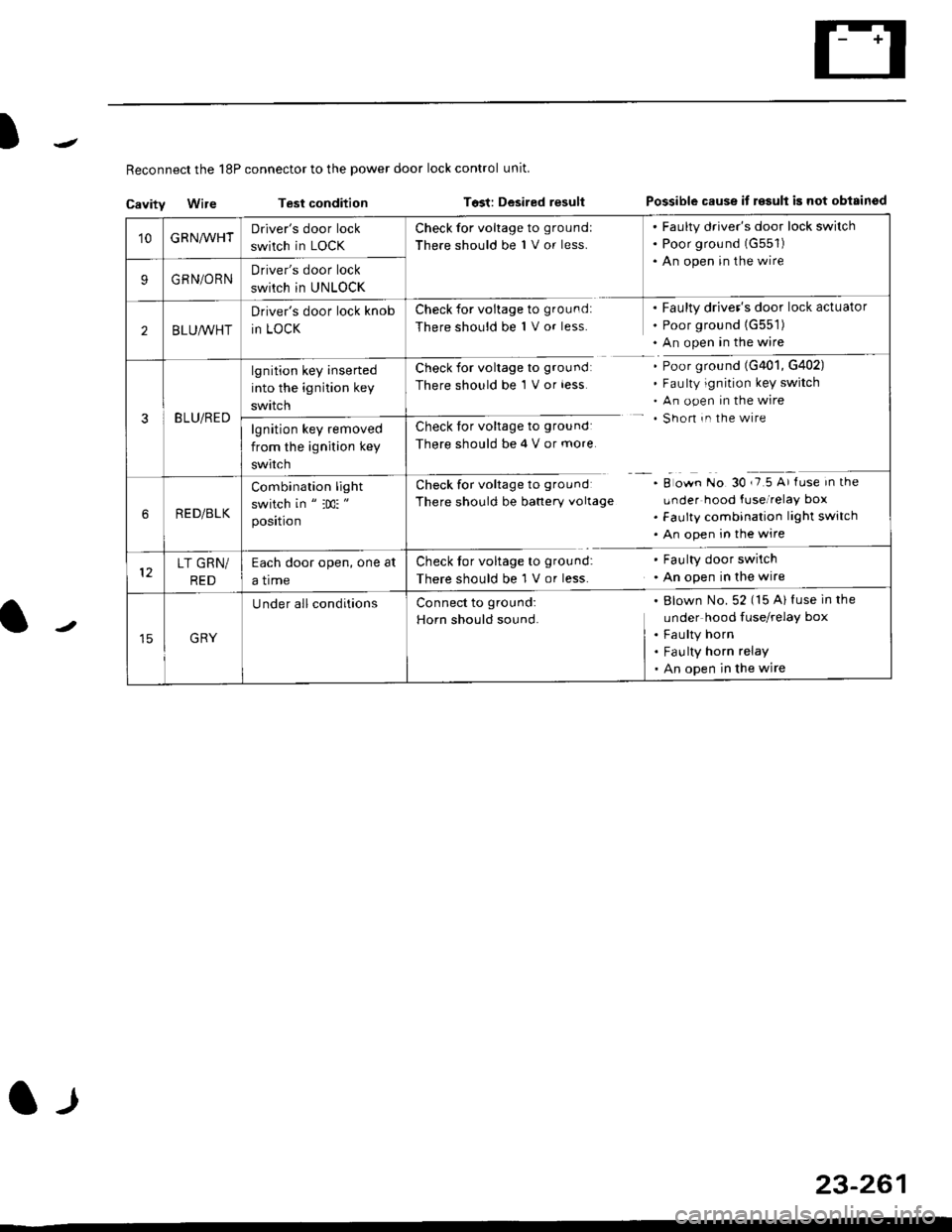
Reconnect the 18P connector to the power door lock control unit
Cavitv Wire Test condition Tost: Desired resultPossible cause it r€sult is not obisinod
23-261
l-l
'10GRNA/VHTDriver's door lock
switch in LOCK
Check for voltage to groundl
There should be 1 V or less.
. Faulty driver's door lock switch. Poor grou nd (G551)
. An open in the wire
9GRN/ORNDriver's door lock
swirch in UNLOCK
2BLU,ryVHT
Driver's door lock knob
in LOCK
Check for voltage to ground:
There should be 1 V or less.
Faulty driver's door lock actuator
Poor ground {G551)
An open in the wire
3BLU/RED
lgnition key inserted
into the ignition key
swttcn
Check for voltage to groundl
There should be 1 V or less
Check for voltage to ground:
There should be 4 V or more
Ch."k f"r ".lt"r" t. g|'"r^d
There should be banery vollage
Poor ground (G401, G402)
Faulty ignition key switch
An open in the wire
Shon in the wire
A o*n tto gO ,i5 A' fr." in tf'"
Lrnder hood fuse/relay box
Faulty combination light switch
An open in the wire
lgnition key removed
from the ignition key
swtrcn
RED/BLK
Combination light
switch in " :m: "
position
LT GRN/
RED
Each door open, one at
a trme
Check tor voltage to ground:
There should be 1 V or less.
Faulty door swilch
An open in the wire
GRY
U nder all conditionsBlown No. 52 (15 Al fuse in the
under hood fuse/relay box
Faulty horn
Fau lty horn relay
An open in the wire
Connect to ground:
Horn should sound.
Page 1733 of 2189

)
l-l
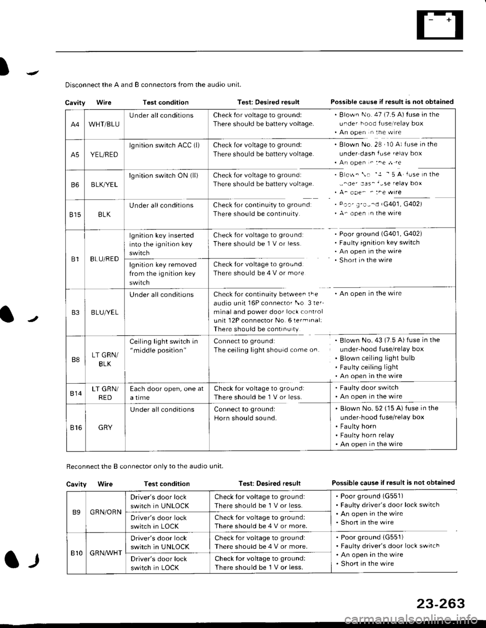
Disconnect the A and B connectors from the audio unit.
Cavity WireTest conditionTest: Desired resultPossible cause if result is not obtained
Reconnect the B connector only to the audio unit.
Cavity WireTest conditionTest: Desired resultPossible cause iI result is not obtained
B9GRN/ORN
Driver's door lock
switch in UNLOCK
Check for voltage to ground:
There should be 1 V or less.
. Poor ground 1G551). Faulty driver's door lock switch. An open in the wire. Short in the wireDriver's door lock
switch in LOCK
Check for voltage to grou nd:
There should be 4 V or more.
810G R NAr'r'HT
Driver's door lock
switch in UNLOCK
Check for voltage to ground:
There should be 4 V or more.
. Poor ground (G551)
. Faulty driver's door lock switch. An open in the wire. Shon in the wireDriver's door lock
switch in LOCK
Check lor voltage to ground:
There should be I V or less.
23-263
A4WHT/BLU
LJnder all conditionsCheck {or voltage to ground:
There should be battery voltage.
. Blown No. 47 (7.5 A) tuse in the
under hood fuse,i relay box. An open n the w re
A5YEL/RED
lg nition swirch ACC (l)Check for voltage to ground:
There should be battery voltage.
Blown No. 28 , I0 A) f use in the
under dash fuse.elay box
An open " :ne n re
Check for voltage to ground:
There should be battery voltage.
Check for continuity to groundr
There should be continuity.
B o$. \. '.1 - 5 A' iuse n the
,,^oe' aas_'-se relay box
A_ ooe^ ' :ne wrre
Pc.' E'o--d rG401, G402)
A- ooen n lhe wire
B6B LK,/YE L
lgnition switch ON0l)
8158LK
Under all conditions
B1BLU/RED
lgnition key inserted
into the ignition key
swrtch
Check for voltage to ground:
There should be 1 V or less
Check for voltage to ground:
There should be 4 V or more
Poor ground (G401, G402)
Faulty ignition key switch
An open in the wire
Short in the wire
An open in the wireCheck for continuity berwee. lFe
audio unit 16P connector l-o 3ler-
minal and power door lock control
unit 12P connector No. 6 lermrnal:
There should be continu ty
lgnition key removed
from the ig nition key
swtlcn
B3B LUlt/E L
U nderall conditions
B8LT GRN/
BLK
Ceiling light switch in"middle position"
Connect to ground:
The ceiling lighr shouldcome on.
Blown No.43 (7.5 A) fuse in the
under-hood Iuse/relay box
Blown ceiling light bulb
Fau lty ceiling light
An open in the wire
814LT GRN/
RED
Each door open, one at
a time
Check tor voltage to ground:
There should be'l V or less.
. Faulty door switch. An open in the wire
Br6GRY
U nderall conditionsConnect to groundl
Horn should sound.
. Blown No. 52 ('15 A) fuse in the
under-hood fuse/relay box
. Fau lty horn. Faulty horn relay. An open in the wire
Page 1744 of 2189
Circuit Diagram
UNDER-HOOD FUSE/RELAY 8OXIGNITIONSWITCH
WHT/8LI( +WHT
Brake systsm light
passenger's airbag
l----ltlI DUMMY II BESISTOR I
tll
tl
la rl
MEMORY ERASESIGNAT IMES)CONNECTOR I2P)
GRY{GRN)
I
BRN BRN
tl.-l- .-r-\./ \./
ECM/PCM SERVICECHECKCONNECTOR
ILT 8LU
I
t'7
DATA LINKCONNECTOR{DLC) {r6P)
GRY GRY(GRN) IGNN)
V:
G801
Teminalside oi thal€ terminals
24-6
4''
SRS UNIT TERMINALSG40tG402
SBS INDICATOR CIRCUIT{ln the gauge assembly)
PGM_FI
DRIVER'SAIRBAGINFLATOR
10 14 r 13 6 7(VAl 3{VBlSRS UNIT16 17 t5 9 18 8
Page 1777 of 2189

.J
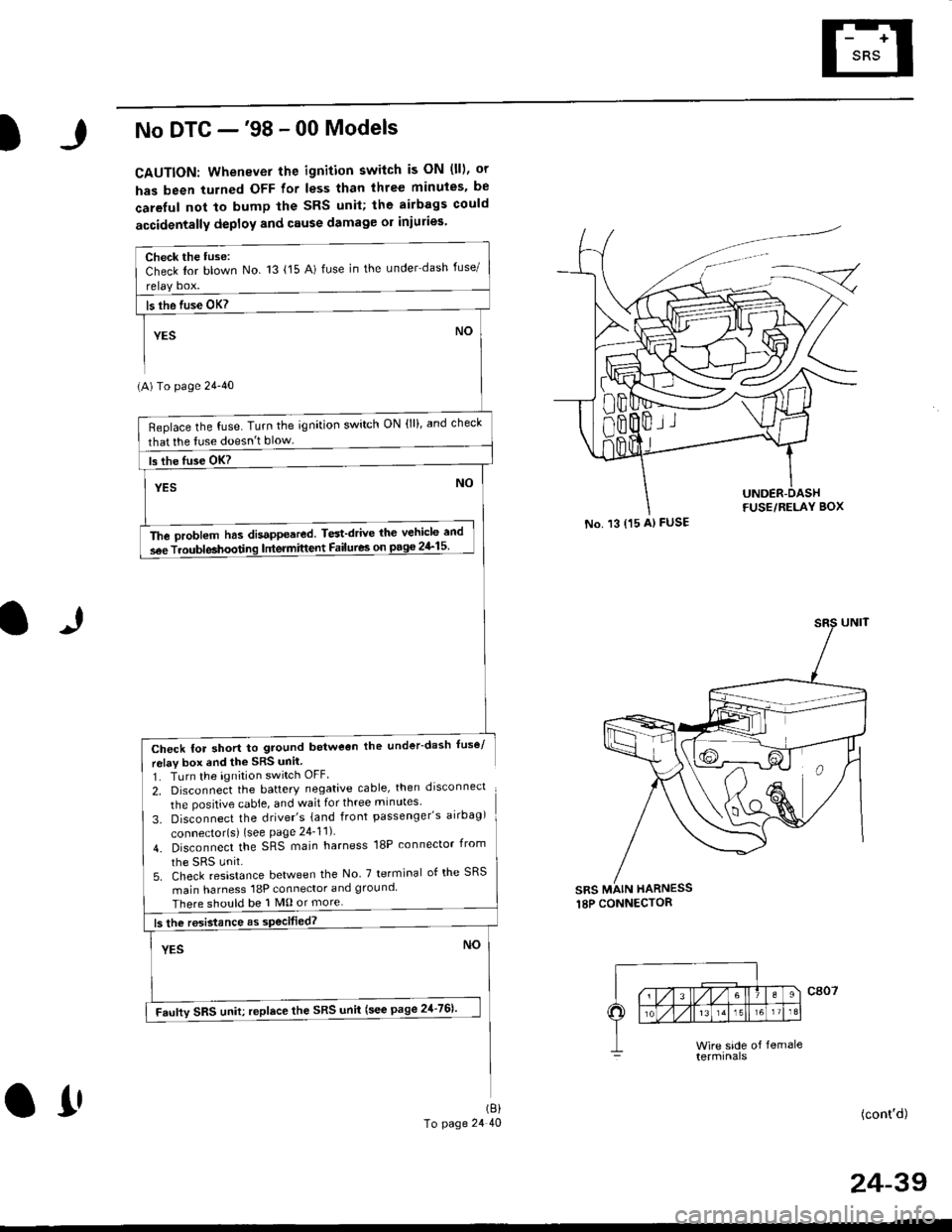
No DTC -'98 - 00 Models
CAUTION: Whenever the ignition switch is ON (ll), or
has been turned OFF for less than three minuies. be
careful not to bump the SRS unil; the airbags could
accidentally deploy and cause damage or iniuries
(A) To page 24'40
Check for short to ground betweon the under-dash fuse/
relav box end the SRS unil
1. TLrrn the ignition switch OFF
2, Disconnect the battery negative cable, then drsconnect
the positive cable, and wait for three minutes'
3. Disconnect the driver's {and front passenger's airbag)
connector{s) {see Page 24_11)
4. Disconnect the SRS main harness 18P connector irom
5. Check resistance between the No 7 terminal of the SRS
main harness 18P connector and ground
There should be 1 M0 or more
(cont'd)
No. 13 {15 A) FUSE
sRs MAIN HARNESS
Check the tuse:Check Ior blown No 13 {15 A) fuse in the under dash fuse/
Beplace the fuse. Turn the ignition switch ON (lll, and check
that lhe tuse doesn't blow
The oroblem has disappeared. Test'drive thc vehicle and
s6e Troubleahoodng lntermittent Failures on pago 2&15
Faufty SRS uniu replace the SRS unii (see page 21-761'
(8)
To page 24 40O1'
24-39
Page 1817 of 2189

Contents
How to Use This Manual ICircuit Schematics (see Circuit Index)Fuse/Relaylnformation 6Ground-to-Componentslndex 6-6ComponentLocationPhotooraohs 201Conriector Views 202
Circuit Index
Accessory power socket 155Air conditionerAir delivery'96198 models 61'99-'00 models 61-2Blower controls'96198 models 60'99100 models 60-1Compressor controls 62Fans 63Anti-lock brake system (ABS) 44A/T gear position indicatorCVT 89All except CVT 89-1Automatic transmission controlsAll '96-'98 models except CVT and GX 39All '99100 models except CVT 39-8All GX models 39-8'96-'�98 CVT 39-4'99100 cw 39-12Back-up lightsCoupe and Sedan 110Hatchback l'10-1Brake lightsAll Coupes and'96-'98 Sedans 110-15'99-'00 Sedans 110-16Hatchback 110-17Brake system indicator light'96198 models 7'1'99100 models 71-1Ceiling light 114-3Charging system 22Condenser fan 63Console lights 114Cruise control 34Dash lights 114Daytime running lights 110- 13Engine coolant temperature gauge 81-1Fog lights 110-10Front parking lights 110-2Fuel gauge 81-1Fuse/relay boxUnder-dash 6Under-hood 6-4Underhood ABS 6-3Gauges 81Ground distribution 14Ground-to-Componentslndex 6-6Hazard warning lightsAll except '99100 Sedans 110-6'99100 Sedans 110-8Headlights 110-12Headlight switch 100Heater - See Air ConditionerHorn'96197 models 40'98 model 40-1'99100 models 40-2lgnition key reminder 73lgnition systemAll '96198 models except Dl685 20All '99100 models except D16Y5 with Mn 2O-2All D1685 engines 20-2'99-'00 D 16Y5 with M/T 20
lndicators 80Integrated control unit 70lnterlock systemAll except'96J98 CVT 138'96198CVT 138-1License plate lightsAll Coupes and '96-'98 Sedans I l0-3'99100 Sedans 1 10-4Hatchback 110-5Low fuel indicator light 74Moonrool'96197 models |22'98-'00 models 122-1Odometer 81Oil pressure indicator light 80-3Power distributionBattery to ignition switch, fuses, and relaysFuses to relays and components 10-2Power door locksAll models without keyless entry 130'96-'98 models with keyless entry 130-2'99100 models with keyless entry 130-12Power mirrorsWithout detogger 141With defogger '141-2
Power windows 120Programmed fuel injection system (PGNr-Fl)All '96-98 models except D1685 23All '99-'00 models except D16Y5with M/T and D1685 24All D1685 engines 25'99100 D16Y5 with M/T 23Radiator fan 63Rear window defogger'96-,98 models 64'99100 models 64-1Seat belt reminder 73Security system'96.'98 USA HX, LX, EX 133'96-'98 Canada EX, Si 133'99TOO USA HX, LX, EX, DX.V Si 133-4'99100 Canada EX, Si 133-4All CX and DX models 133-8Speedometer 81Starting systemA./T (All except Dl685) 21A"/r (D16Bs) 21-1Manualtransmission 21-2Slereo sound system 150Supplemental rastraint system (SRS) 47Tachometer 81TailliqhtsAllboupes and'96-'98 Sedans 110-3'99100 Sedans 1 10-4Hatchback 110-5Trunk light 114-3Turn signal lightsAll except'99100 Sedans 110-6'99-'00 Sedans 1 10-8Vehicle speed sensor (VSS) 33Wiper/washerFront 91Rear 92
10
Page 1837 of 2189
- Under-hood ABS Fuse/Relay Box
Fuse
Number
(To underhood ABS fuse/relay box w re harness)
ABS pump motor
| 10-14 I ABS control unit
i ABS control unit
component or circuit ProiectedFuse Name
PUMP MOTOR
I ABS +B
ABS PUMPMOTOR RELAY(To main wire harness)
(To rnain wlre harness)
I!,ITR CHECK
6.3
Page 1838 of 2189
Fuse/Relay Information lcont'd)
- Under-hood Fuse/Relay Box
Front View
T'102(To engine wire harness)
LO
T1Oo starter cables)
*: Not Used
Rear View
c353To main wire harness
DE
tr
tr
tr
t-l
IJ
n
tJ
t-l51
IJ
n
IJ
n5T
IJ
[[o main wire harness)
6-4
ffo main wire harness)fto main wire harness)
Page 1843 of 2189

I
t
I
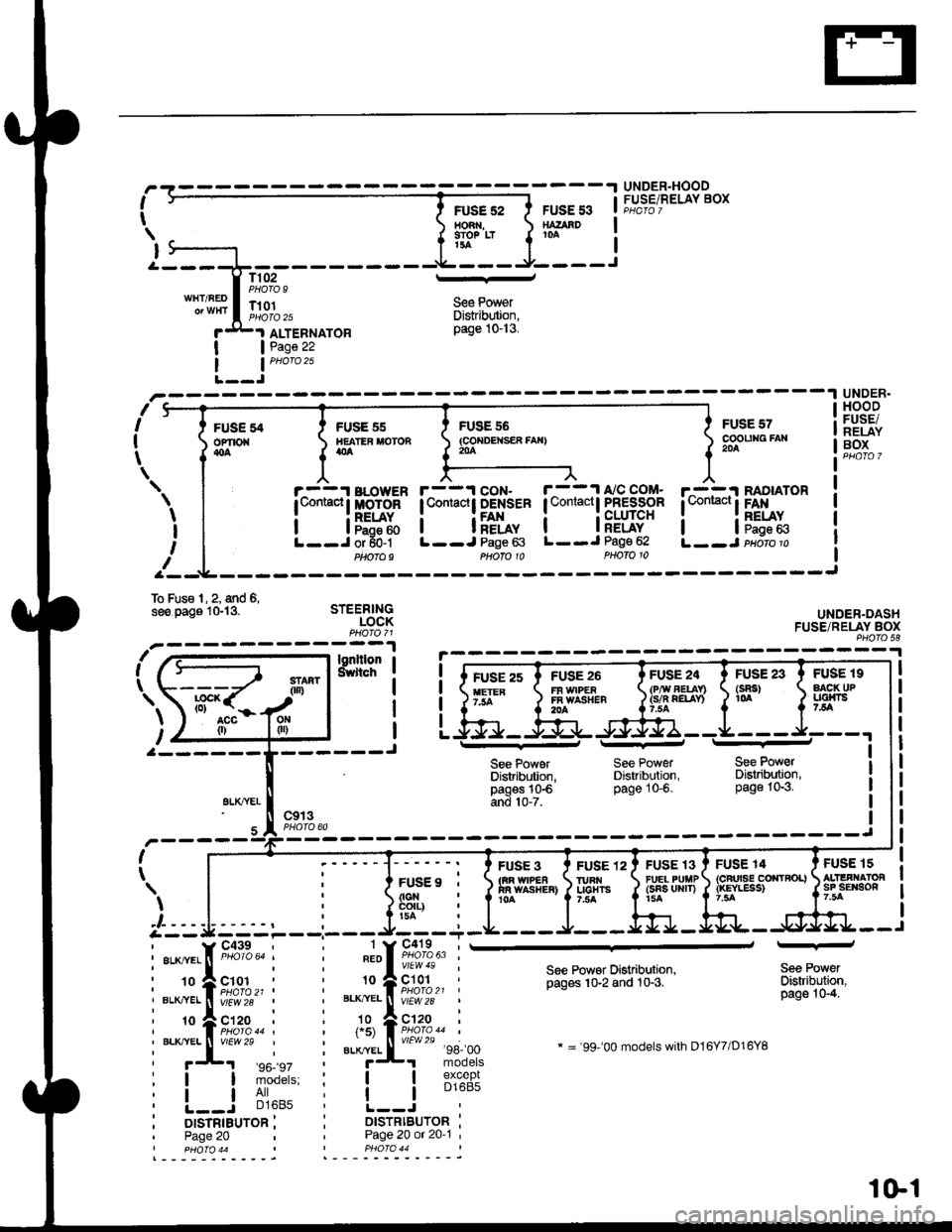
UNDER-HOODFUSE/RELAY BOXFUSE 52HO3 ,9IO? LTt3a
FUSE 53SATAAD10A
T102PHOTO 9l--
S€e PowerDistrib$ion,page 10-13.
WHT/REDT101PI1oIO 25
I
IJ
I
I
FUSEofiro{{oa
ALTEBNATORPage 22
nI
I
t
--1 UNDER.
sFUSE 55IIEATER MOTONatla
r^-::r BLowER| t,omacl I MoToR
i lF5:ftL--J or 50-1Ptaofo9
FUSE 55(co{DEtsER fAx}204
FUSE 57cooutag FAr204
r^-::I RADIATOR
l*"*!F*x.L--J paoro p
HOODFUSE/NELAYBOX
UNDER-DASHFUSE/RELAY BOXPHO|O 58
FUSE 19AACK UPLlalni75A
FUS€ 15ALIIFI.IATORsF sErson7.5A
\
I
I
If
r--1 coN- r--11'/C COM-lContactt DENSER I Contactl PFESSOR
i i[f*, i iFLug"L--J Page 63 L--J Page 62
To Fus€ l, 2, and 6,see oaos lGl3. STEERINGLOCK
\
l,ut-a--- ---------J
gLXTYEI
FUSE 23(sRs)1(rA
Phofo 10
See PowerDistribdion,pagos 10€and 10-7.
FUSE 3tm w|PEain wAsr{ER}10A
PHOTO 10
See PowerDistribution,page 10-6.
FUSE 24(P,ry AEUn(s/n QELAY)
FUSE 13FU€L PUIIP(sns uRrT)15A
See PowerDisaibution,page 10-3.
FUSE 14{cFrrsE corrtRoL}{rcYLESS)
c913I
I
FUSE9 ,
FUSE 12IURI{UCHTS7,trA
) | , i ]si"ii:-' r|r::::---'--- J/--_-r
i::{;iil i i".ii.l ,#,;:|'-
i-:'ff1tu;.,,, i *=ft;;***
See Powsr Distribution,pages 10-2 and 10-3.
* = '99-'00 models with D16Y7/D16YB
Sea PowerDistribuiion,page 10-4.
:! iii'^': i i lB1%"f;
i L-=r -','lo' i !.---i..-^- ii orsrnrauron i i DtsrRtBUroR :' Page 20 Page 20 or 20'1 '
%[-#
I pHOfO 44 PHO|O 44
1Gl