Page 1406 of 2189
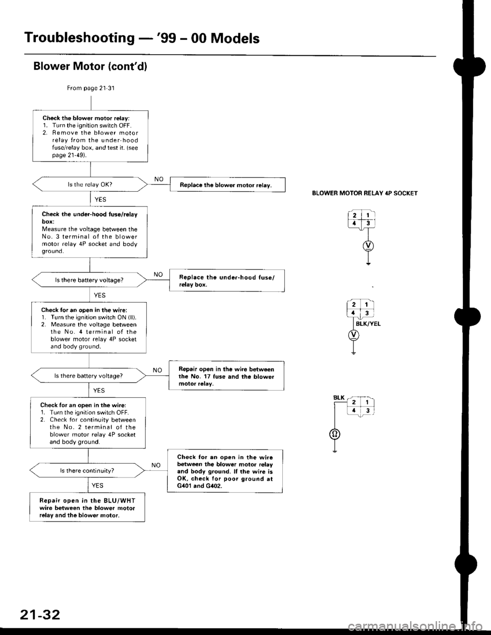
Troubleshooting -'99 - 00 Models
From page 21-31
Check the blower motor relay:1. Turn the ignition switch OFF.2. Remove the blower motorrelay from the under hoodfuse/relay box, and test it- (seepage 21'49).
Replace the blower motor relay.
Check the under-hood tuse/relaybox:Measure the voltage between theNo. 3 terminal of the blowermotor relay 4P socket and bodyground.
Check tor an open in the wire:1. Turn the ignition switch ON (ll).
2. Measure the voltage betweenthe No. 4 terminal of theblower motor relay 4P socketand body ground.
Repair opon in lhe wire betweenthe No. 17 fuse and the blowetls there battery voltage?
Check for an open in the wire:1. Turn the ignition switch OFF.2. Check for continuity betweenthe No. 2 terminal of theblower motor relay 4P socketand body ground.
Check lor an ooen in the wirebetween the blowor motor relayand body ground. It the wiie isOK, check for poor ground atG401 and G402.
ls there continuityl
Repair open in the BLU/WHTwiae between the blower motorrelay and the blower motor,
BLOWER MOTOR RELAY 4P SOCKET
21-32
Page 1407 of 2189
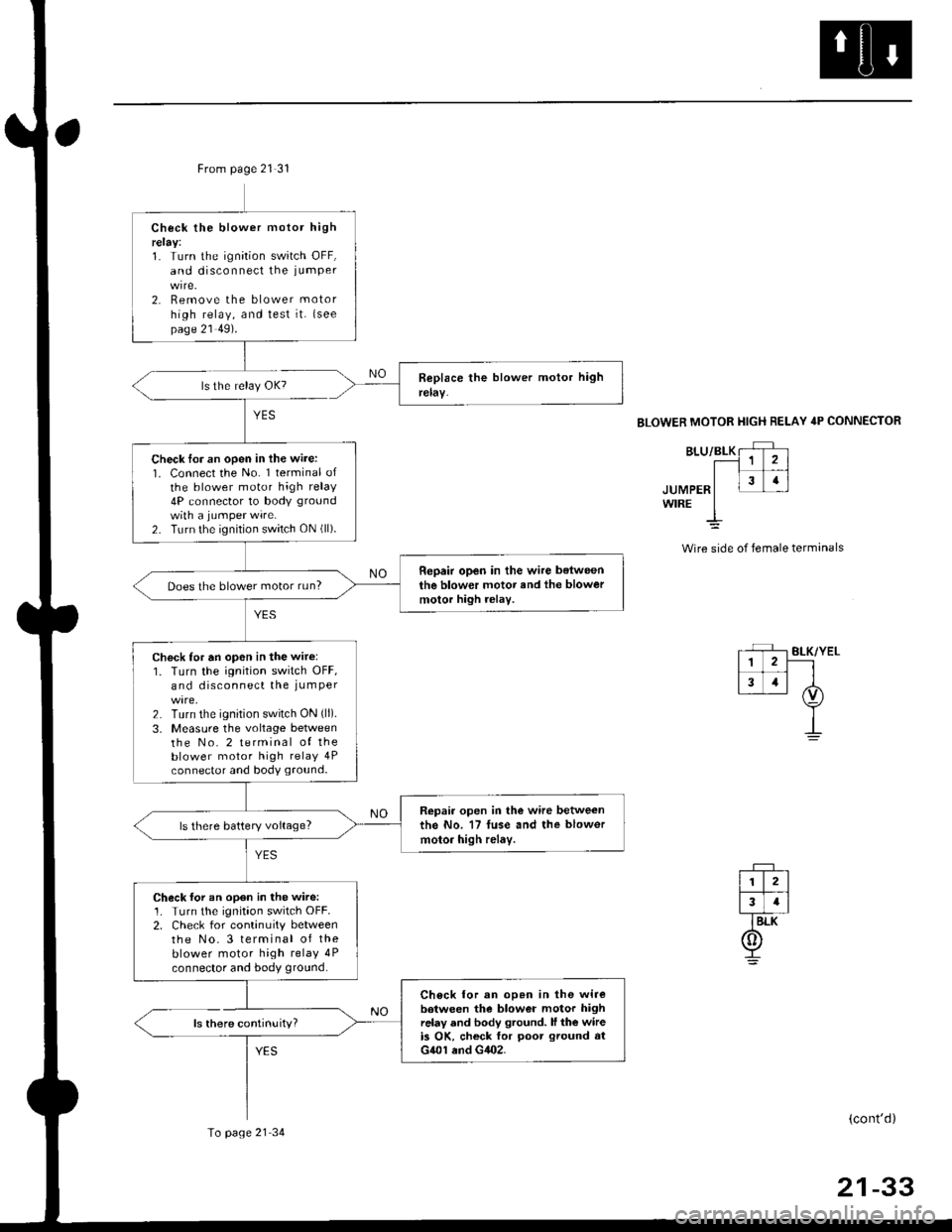
From page 21 31
ls there continuity?
YES
Check the blower motor highrelay:1. Turn the ignition switch OFF,and disconnect the iumPer
2. Remove the blower motor
high relay, and test it. {seepage 21 49).
Check lor an open in the wire:1. Connect the No. 1 terminal ofthe blower motor high relay4P connector to body ground
with a jumPer wire.2. Turn the ignition switch ON (ll).
Repair open in the wire belweenthe blower motor and the blowermotor high rolay.Does the blower motor run?
Check for an op6n in the wir6:1. Turn the ignition switch OFF,and disconnect the iumPer
2. Turn the ignition switch ON (ll).
3, Measure the voltage betweenthe No. 2 terminal of theblower motor high relay 4Pconnector and body ground.
Repair open in the wire betweenthe No. 17 fuse and the blowor
motor high relay.ls there battery voltage?
Check for an open in the wire:1. Turn the ignitaon switch OFF.2. Check for continuity betweenthe No.3 terminal of theblower motor high relay 4P
connector and body ground.
Ch6ck lor an op.n in the wirebotween the blower motor highrelay and body ground. ll the wireis OK, ch6ck for poot ground atG401 end G402.
To page 21 34
BLOWER MOTOR HIGH RELAY 4P CONNECTOR
JUMPERWIRE
Wire side of female terminals
(cont'd)
21-33
Page 1408 of 2189
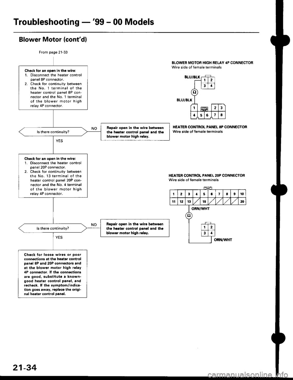
Troubleshooting -'99 - 00 Models
Blower Motor {cont'dl
BLOWER MOTOR HIGH RELAY 4P CONNECTORWire side of female terminals
BLU/BLK
BLU/ALK
HEATER OONTROL PANEL 8P CONNECTORwir€ sido ot f€male torminals
HEATER CONTROL PANCL 2OP CONNECTORWire side of female terminals
From page 21-33
Check tor an opgn in the wiro:1. Disconnect the heater controlpanel 8P connector.2. Check lor continuity betweenthe No. 1 terminal of theheater control panel 8P con-nector and the No. 1 terminalot the blower motor highrelay 4P connector.
Repsi. op€n in the wir. betw.enthe h..t.r contrcl p.ncl .nd thoblowar motor high rahy.
Ch€ck for an opon in the wir6:1. Disconnect the heater controlpanel 20P connector.2. Check for continuity betweenthe No. 13 terminal of theheater control panel 20P con-nector and the No. 4 terminalof the blower motor highrelay 4P connector.
Ropair opon in tho wiro botwoontha hartor cor rol pangl rnd thablower motor high .elay.
Ch.ck for looso wiros or poor
conn€dions at th6 heato. controlpanel 8P and 20P connectoB andat the blowol motor high relty4P connoctor. It tho connoctionsare good, substitute a known-good heatcr control panel, andrecheck. It the symptom/indica-tion goos away, rgplaco the oiigi-nal heater control oanol.
2
34
o
t2
a568
I23a5078I10
11121315,/1,/1,/m
ORN/WHT
o
12
34
OBN/WHT
21-34
Page 1409 of 2189
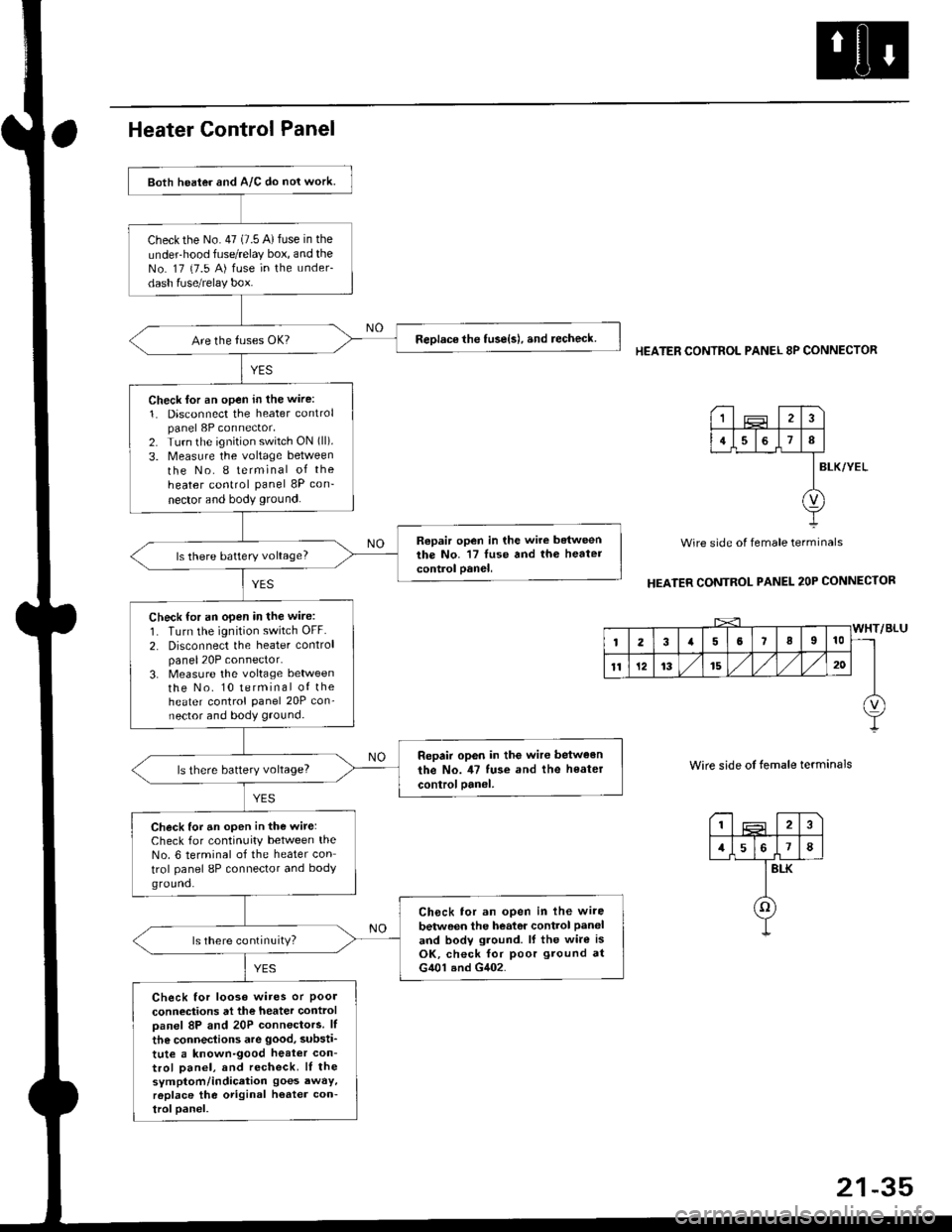
Both heater and A/C do nol work.
checkthe No.47 (7.5 A)fuse in the
under-hood fuse/relay box, and theNo. 17 {7.5 A) fuse in the under-
dash fuse/relay box.
ReDlace the tuse{s), and recheck.
Check lor an open in the wire:
1. Disconnect the heater controlpanel 8P connector,2. Turn the ignition switch ON (ll).
3. Measure the voltage between
the No. I terminal of the
heater control panel 8P con-
nector and body ground.
Repair open in the wire betweenthe No. '17 luse and th6 heatercontrol oanel,ls there battery voltage?
Check for an open in the wire:
1. Turn the ignition switch OFF.
2. Disconnect the heater controlpanel20P connector.3. Measure the voltage lletweenthe No. 10 terminal of theheater control Panel 20P con-nector and body ground.
Repair op6n in the wir€ between
the No. il7 tuse and the heater
controloanel,ls there battery voltage?
Check for an open in the wite:Check for continuity between theNo. 6 terminal of the heater con
trol panel 8P connector and bodyground.
Ch6ck tor an open in lhe wire
betwoen the heator control Paneland bodv ground. lf the wire isOK, check for poor ground atG401 and G402.
ls there continuity?
Check for looso wires or Poolconneciions at the heater controloanel 8P and 20P connectors. lf
the connections are good, substi'
tute a known-good heat€r con-trol Danel, and recheck. lI thesymptom/indication goes awaY,r6place the original h€ater con-troloanel.
HEATER CONTROL PANEL 8P CONNECTOR
BLK/YEL
Wire side of female terminals
HEATER CONTROL PANEL 2OP CONNECTOR
Wire side of temale terminals
I2
1578
BLK
o
1
4I
v
Page 1412 of 2189
Blower Unit
Overhaul
NOTE:
RECIRCULATIONCONTROL MOTORTest, page 21-48
aBefore reassembly. make sure that the recirculation control door and linkage move smoothly without binding.
When attaching the recirculation control motor, make sure its positioning will not allow the recirculation control door
to be pulled too far.
After aftaching the recirculation control motor, connect power and ground, and watch the movement of the recircula-
tion control door.
BLOWERTest, page 2'l 9{'96 - 98 modebl
POWER TRANSISTOR l'99 - 00 modeblTest, page 21-50
Test, page 21'10 ('96 98 models) orpage 21'31 ('99 00 models)
m
MOTOR
2134
Page 1413 of 2189
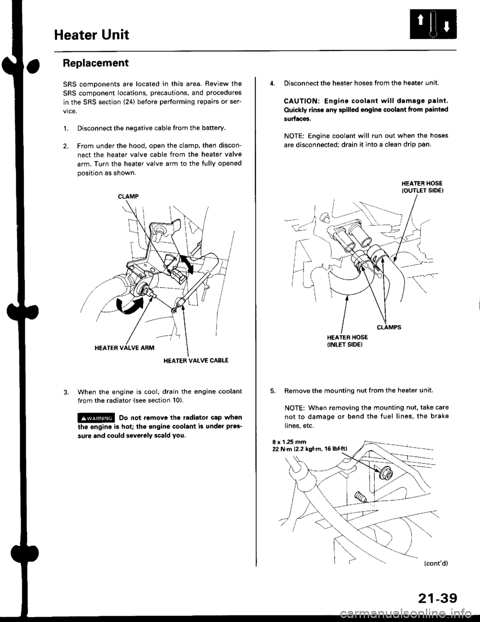
Heater Unit
Replacement
SRS components are located in this area. Review the
SRS component locations, precautions, and procedures
in the SRS section {24} before performing repairs or ser-
L Disconnect the negative cable from the battery.
2. Frcm under the hood, open the clamp, then discon-
nect the heater valve cable from the heater valve
arm. Turn the heater valve arm to the fully opened
position as shown.
When the engine is cool. drain the engine coolant
from the radiator (see section 10).
!@ Do not remove the radiator cap when
the engine is hot; the ongine coolant is under pres'
surg and could severely scald you.
CLAMP
HEATER VALVC CABLE
4. Disconnect the heater hoses from the heater unit.
CAUTION: Engine coolant will damage p8int.
Ouickly rinse any spilled engins coolant from painted
su aces,
NOTE: Engine coolant will run out when the hoses
are disconnected; drain it into a clean drip pan.
5. Remove the mounting nut from the heater unit.
NOTE: When removing the mounting nut, take care
not to damage or bend the fuel lines, the brake
lines, etc.
I x 1 .25 mm22 N.m {2.2 kgl.m, 16lblftl
21-39
Page 1420 of 2189
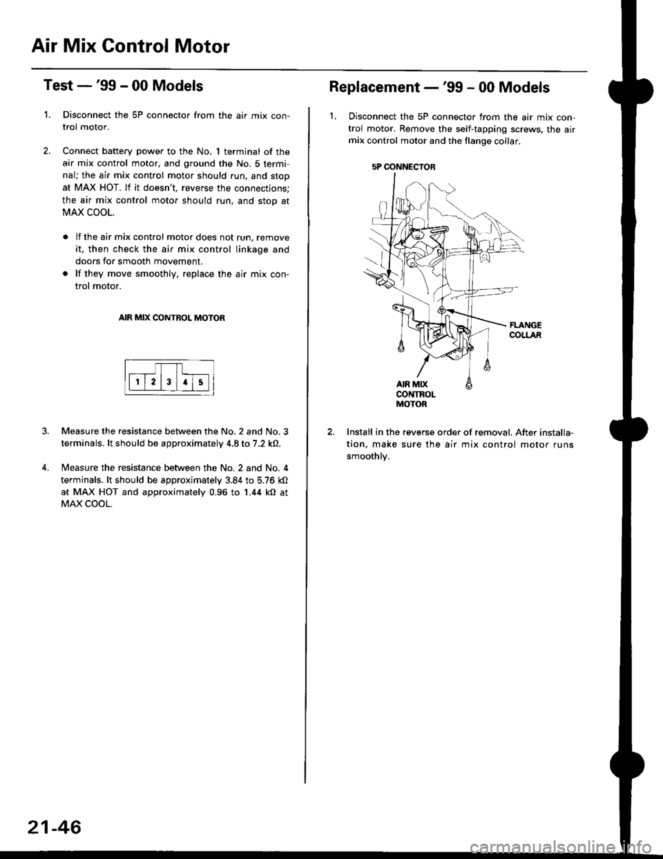
Air Mix Gontrol Motor
't.
Test -'99 - 00 Models
Disconnect the 5P connector from the air mix con-
trol motor.
Connect battery power to the No. 1 terminal of the
air mix control motor, and ground the No. 5 termi,
nal; the air mix control motor should run, and stop
at MAX HOT. lf it doesn't, reverse the connections;
the air mix control motor should run, and stop at
MAX COOL.
lf the air mix control motor does not run, remove
it, then check the air mix control linkage and
doors for smooth movement.
lf they move smoothly, replace the air mix con-
trol motor.
AIR MIX CONTROL MOTOR
Measure the resistance between the No.2 and No.3
terminals. lt should be approximately 4.8 to 7.2 kO.
Measure the resistance between the No. 2 and No. 4
terminals. lt should be approximately 3.84 to 5.76 kO
at MAX HOT and approximately 0.96 to 1.44 kO at
MAX COOL.
21-46
5P OONNECYOB
Replacement -'99 - 00 Models
1, Disconnect the 5P connector from the air mix con-
trol motor. Remove the self-tapping screws, the airmix control motor and the flange collar.
CONTROLMOTOR
Install in the reverse order of removal. After installa-
tion, make sure the air mix control motor runs
smoothly.
Page 1421 of 2189
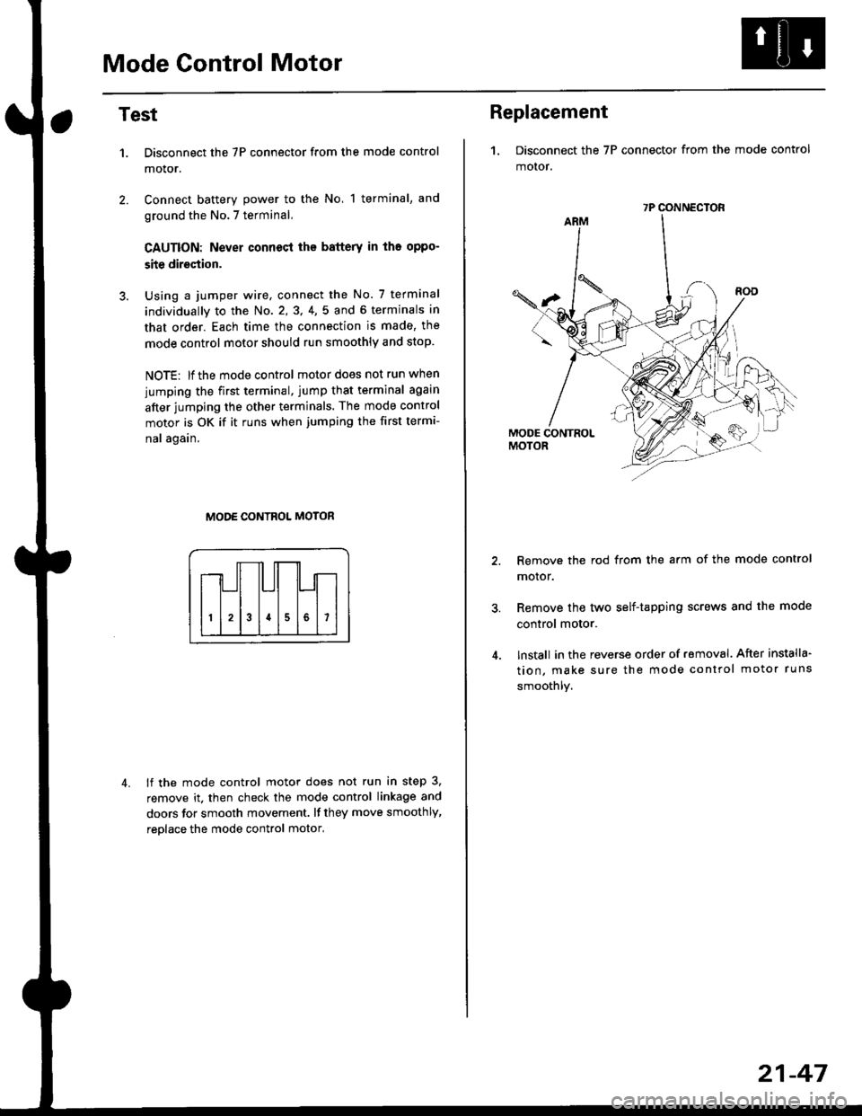
Mode Control Motor
2.
Test
1.
4.
Disconnect the 7P connector from the mode control
motor.
Connect battery power to the No, 1 terminal, and
ground the No.7 terminal,
CAUTION: Never connecl the battery in iho oppo-
site direction.
Using a jumper wire, connect the No. 7 terminal
individually to the No. 2,3, 4,5 and 6 terminals in
that order. Each time the connection is made, the
mode control motor should run smoothly and stop.
NOTE: lf the mode control motor does not run when
jumping the first terminal, jump that terminal again
after jumping the other terminals. The mode control
motor is OK if it runs when jumping the first termi-
nal again.
MODE CONTROL MOTOR
lf the mode control motor does not run in step 3,
remove it. then check the mode control linkage and
doors for smooth movement. lf they move smoothly,
reolace the mode control motor,
Replacement
1. Disconnect the 7P connector from the mode control
motor,
Remove the rod from the arm of the mode control
motor.
Remove the tyvo self-tapping screws and the mode
control motor.
lnstall in the reverse order of removal. After installa'
tion, make sure the mode control motor runs
smoothly.
7P CONNECTOR
21-47