1997 HONDA CIVIC height
[x] Cancel search: heightPage 43 of 2189
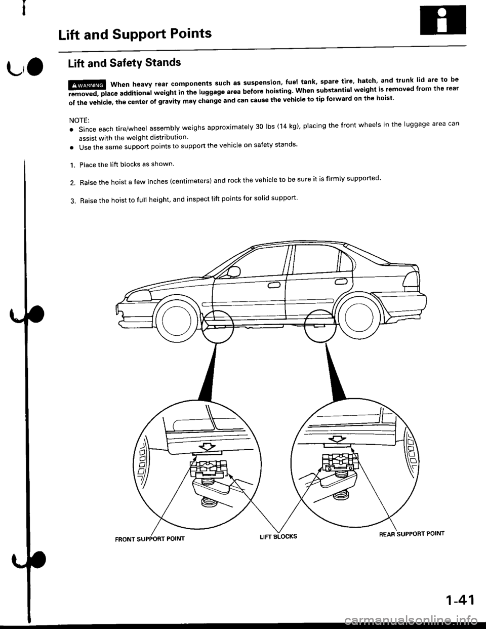
Lift and SupPort Points
L,O
Lift and SafetY Stands
t!ffi when heavv rear components such as suspension' fuel tank' spare tire' hatch' and trunk lid are to be
-aEremoved, place additional wetght Inihe luggage arga before hoisting. when substantial weight is lemoved from the rear
of the vehicls. the center of gravity may change and can cause the vehicle to tip tolward on the hoisi
NOTE:
. Since each tire/wheel assembly weighs approximately 30 lbs (14 kg)' placing the front wheels in the luggage area can
assist with the weight distribution
. Use the same support points to suppon the vehicle on safety stands'
Place the lift blocks as shown.
Raise the hoist a lew inches (centrmeters) and rock the vehicle to be sure it is firmly supported'
Raise the hoist to full height, and inspect lift points for solid support
1.
2.
3.
REAR SUPPORT POINT
1-41
Page 47 of 2189
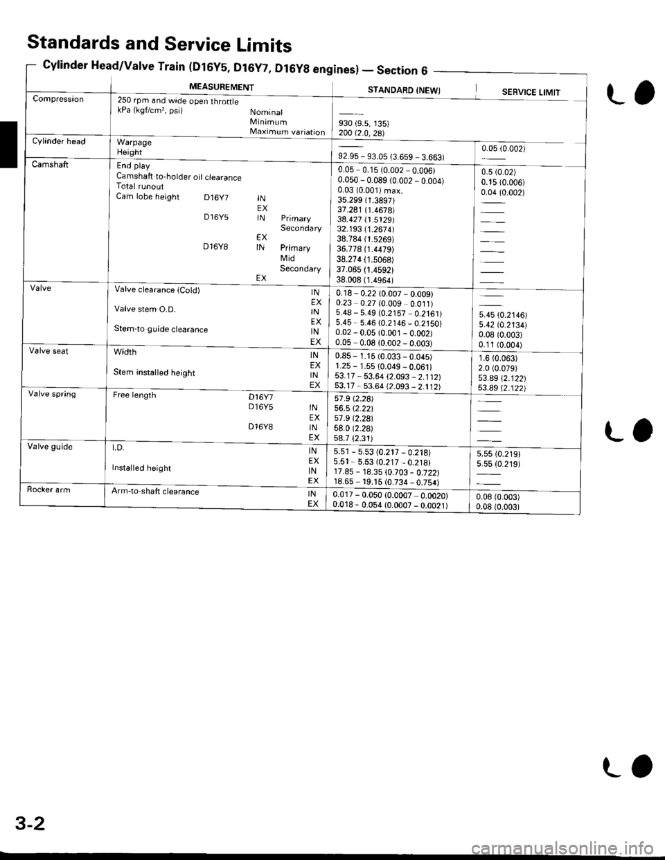
(urbY5, ul6Y7, Dl6Yg enl
MEASUREMENT
Sines) -Section6 -
STANDARD INFWTCompression250 rpm and wide open throftlekPa {kgf/cm,, psi) NominalMinimumMaximum variationWarpageHeight
End play
Camshaft to-holder oil clearanceTotal runoutCam lobe height D16y7
D16Y5
D16Y8
INEXIN
EXIN
EX
Secondary
PrimaryMidSecondary
930 {9.5, 135)200 12 0 ?R\Cylinder head
92.95 - 93.05 {3.659 3.663)0.05 {0.002)
Camshaft0.05,0.15 (0.002 0.006)0.050 - 0.089 (0.002 _ o.oo4)0.03 (0.001)max.
35.299 (1.3897131.241 /.1.4678)38.427 (1.5129)32.193 11 .267 4l38.784 (1.5269)
36.778 (1.4479)
38.274 (1.5068)
37.065 .4592)38.008 (1.4964)
0.5 (0.02)
0.15 (0.006)
0.04 (0.002)
=
Valve clearanca {Cold)
Valve stem O.D.
Stem-to guide clearance
width
Stem insta ed height
Free lengrh Dt6y7D16Y5
INEXINEXINEX
INEXINEX
INEXINEX
INEXINEX
D16Y8
t.D.
Installed height
0.18 - 0.22 10.007 - 0.009)0.23 0.27 (0.009 0.011)5.48 - 5.49 (0.2157 0.2161)5.45 - 5.46 {0.2146 _ 0.2150}0.02 - 0.05 (0.001 _ o.oo2)0.05-008lono2-nnn?l
5.45 (0.2146)
5.42 tO.213410.08 (0.003)
0.11 (0.004)
1.6 (0.063)
2.0 (0.079)
53.a9 \2.122|j$.a9 Q.122)
Valve seat0.85 - 1.15 (0.033 - 0.045)1.25 - 1.55 10.049 - 0.061i53.17 - 53.64 {2.093 _ 2.112)53.17 - 53.64 (2.093 _ 2.112)Valve spring57 .9 (2.2a)
56.5 \2.22157 .9 t2.29l58.0 (2.2a)
58.7 {2.31iValve guide5.51 - 5.53 (0.217 - 0.218)5.51 - 5.53 (0.217 _ 0.218)17.85 - 18.35 \0.103 - 0.722)18.65 19. t5 (0.734 _ 0.754)
5.55 t0.219)5.5s {0.219)
Rocker armArm-to shaft clearanceINEX0.017 - 0.050 (0.0007 0.0020)0.018 - 0.054 (0.0007 - 0.0021)0.08 (0.003)
0.08 (0.003)
Standards and Service Limits
Cylinder Head/Valve Train (Dt6y5, Dt6y7, D
L,
ra
3-2
LO
Page 48 of 2189

Unit of iength: mm (!n)
930 (9.5, 135)20012.0,zal
0.05 - 0.15 (0.002 - 0.006)
0.050 - 0.089 (0.002 - 0.004)
0.0310.001)max.33.088 (1.3027i
36.261 {1.4278)34.978 (1.3771)
32.785 {1.2907)35.720 (1.4063)
34.691 (1.3658)
u*u lo.r,ool5.420 (0.2134)
0.08 (0.003)
0.11 (0.004)
2.0 (0.08)
2.0 (0.08)
38.185 (1.5033)
37.885 (1.4915)
250 rpm (min riand Nominal
wide open throttle Minimum
kPa (kqf/cm'�, psi) Maximum variation
End play
Camshaft-to holder oil clea€nce
Total runoutCam lobe height lN PrimaryMidSecondaryEX PrimaryMidSecondary
0.15 - 0.19 (0.006 - 0.007)*
0.17 - 0.21 (0.007 - 0.008)*
5.475 - 5.485 10.2156 - 0.2159)
5.450 - 5.460 (0.2146 - 0.2150)
0.025 - 0.055 (0.0010 0.0022)
0.050-0.080 (0.0020 - 0.0031)
Valve clearance
Valve stem O.D.
Stem-to-guide clearance
INEXINEXINEX
1.25 - 1.55 {0.049 - 0.061)r.25 - 1.55 (0.049 - 0.061)
37.465 - 37.935 (1.4750 - 1.4935)
37.165 - 37.635 (1.4632 - 1.4817)
INEXINEX
width
Stem installed height
40.92 (1.611)*'
40.91 (1.6111"
36.71 (1.415)
41.96 (1.652)*r
4 r.94 (1.651)*'
free t*gth lN OUTER
5.51 - 5.53 (0.217 - 0.218)5.51 - 5.53 (0.217 - 0.218i12.55 - 13.05 (0.494 0.5'�j4)
12.55 - 13.05 (0.494 - 0.514)
LD. lNEX
Installed height lNEX
0.025 - 0.052 (0.0010 0.0020)
o.o2s - 0.052 {0.0010 0.0020)
Cylinder Head/Valve Train(816A2 engine) - Section
MEASUREMENTSTANDARD INEW)SERVICE LIMIT
*: Measuring point between camshaft and rocker arm'*1: NTHON H;TSUJO manufactured vatve spring. *2: CHUO HATSUJO manutactured valve spnng.
3-3
Page 52 of 2189

Unit of length: mm (in)
Fuel and Emission - Section
MEASUREMENTSTANOARO (NEW)
260 310 (2.7 - 3.2, 38 - 46)
260 - 310 (2.7 - 3.2, 38 - 46i
260 - 310 (2.7 - 3.2, 38 - 46)
210 - 320 Q.A - 3.3, 40 - 47 1
45 {11.9, 9.9)
M/T (neutral) I A/T or C\.T (lE or fd positioni
Fuel paessure
regulator
Pressure wilh fuel pressure regulator vacuum hose
disconnected kPa (kgvcm'�, Psi)D16Y5D 16Y7D16Y881642
FueltankCapacity I (US gal, lmp gal)
E ngineldle speed rpm
016Y5D16Y7D16Y8816A2
u.s.A.CanadaU,S,A.Canada
670 1 506701 50670150700 t 50
7501 507501 507501 50
700 t 50700 I 507001 50750150750 r 50
ldle CO %0.1 max.
Clutch - Serrtion 12
MEASUREMENTSTANDARD {NEWI I SERVICE LIMIT
Clutch pedalPedal height to floor
StrokePedal play
Disengagement height to floorto carpet
16s (6 1/2)130 140 (5 1/8 5 1/2)
12 -21 t1l2 - 13/16183 (3 1/4)44 (1 3/4) min. Reference
FlywheelClutch surface ruoout
Rivet head depthThickness
0.05 (0.002) max.0.15 (0.006)
Clutch disc1.3- 1.9 (0.05 - 0.07)
8.5 - 9.1 (0.33 - 0.36)
0.2 {0.01)5.5 (0.22)
Pressure plateWarpageDiaphragm spring fingers alignment
0.03 (0.001) max0.6 (0.02) max
0.15 (0.006)
1.0 (0.04)
Lro
3-7
lfllHlllllllllrltllli[
Page 63 of 2189
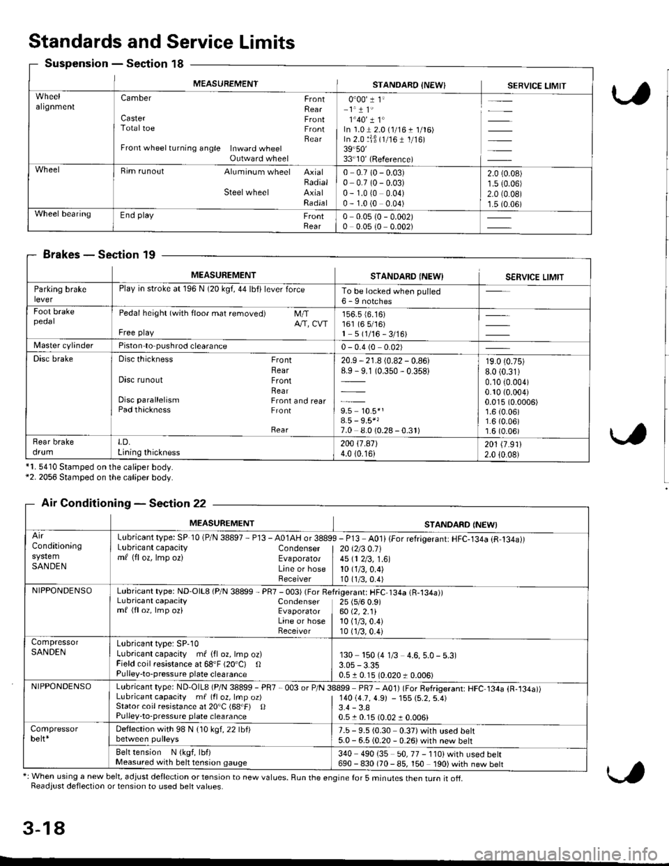
MEASUREMENTSTANOARO INEW}SERVICE LIMIT
algnmenlCamber FrontRearCaster FrontTotaltoe FrontBearFront wheel turning angle Inward wheelOutward wheel
0"00'1 1"-1.1 1'1'40'� I 1"In'1.01 2.0 {1/16 t 1/'16)In 2.0 ljB (1/161 1/16)39.50'�33'10'(Reference)
Bim runout Aluminum wheel AxialBadialSteelwheel AxialRadla I
0 0.7 (0 - 0.03)0- 0.7 (0 - 0.03)0 - 1.0 (0 0.04)0 - 1.0 (0 0.04)
2.0 (0.08)
1.5 10.06)2.0 {0.0B)1.5 (0.06)Wheel bearingEnd play FrontRear0 0.0s (0 - 0.002)0 0.05 (0 0.002)
Standards and Service Limits
Suspension - Section 18
Brakes - Section 19
*1. 5410 Stamped on the caliper body.*2. 2056 Stamped on the caliper body.
Air Conditioning - Section 22
*: When using a new belt, adjust deflection or tension to new values. Run the engine for 5 minutes then turn it of{.Readjust deflection or tension to used belt values.
3-18
MEASUREMENTSTANDARO INEWISERVICE LIMIT
Parklng brakePlay in stroke at 196 N (20 kgf, 44 lbfi lever forceTo be locked when pulled6 - I notchesFoot brakepeoalPedal height (with floor mat removed) M/TA/'T, CVTFree play
156.5 {6.16)161 (6 5/16)1 5(1/16-3/16)
Master cvlinderPiston to pushrod clearance0 - 0.4 (0 0.02)
Disc brakeDisc thickness FrontRearDisc runout FrontRearDisc parallelism Front and rearPad thackness Front
Rear
20.9 - 21.8 (0.82 - 0.86)8.9 - 9.1 (0.350 - 0.358)
9.5 10.5*'8.5 - 9.5*'7.0 8.0 (0.28-0.3r)
19.0 (0.75)
8.0 (0.31)
0.10 (0.004)
0.10 (0.004)
0.015 (0.0006)
1.6 (0.06)1.6 (0.06)'r.6 (0.06)
Rear brakedrumLD.Lining thickness200 17.a7l4.0 (0.16)201 \7 .9112.0 {0.08}
MEASUREMENTSTANDARD INEWI
Conditioning
SANDEN
Lubricant type: SP 10 (P/N 38897 - Pl3 - A01AH or 3889Lubricant capacity Condensermf (floz, lmp oz) EvaporatorLine or hoseReceiver
I - P13 A0li lFor refrigerant: HFC-134a (R,134a))
| 20 \2t3 0.11
I 45 (1 2/3, 1.6)10 (1/3,0.4)
10 t1/3,0.4)NIPPONDENSOLubricant type: ND'O|L8 (P/N 38899 - PR7 - 003) (For ReLubricant capacity Condensermf (floz, lmp oz) EvaporatorLine or hoseReceiver
f.igerant: HFC,134a (R-134a))25 (s/6 0.9)60 (2,2.11
10 (1/3,0.4)
10 (1/3.0.4)
CompressorSANDENLubricant type: SP-10Lubricant capacity ml lfl oz, lmp oz)Field coil resistance at 68'F (20"C) OPulley-to-pressure plate clearance
130 150 (4 1/3 4.6, 5.0 - 5.3)
0.5 r 0.15 10.020 t 0.006)
NIPPONDENSOLubricant type: ND-OlL8 {P/N 38899 - PR7 ,003 or P/N 38899 pR7 - AO1) (For Refrigerant: HFC 134a {R,134a))Lubricant capacity m{(fl oz, lrnpoz) | 14O(4.7,4.9J -15S{5.2.5.4)Stator coil resistance at 20'C (68.F) 0Pulley-to-pressure plate clearance3.4 - 3.80.510.15 (0.0210.006)
Compressorbelt*Deffection with 98 N (1Okgl.22lbllbetween pulleys7.5 - 9.5 (0.30 0.37) with used belt5.0 - 6.5 (0.20 - 0.26)with new belt
Belt tension N (kgf, lbf)Measured with belt tension gauge340 490 i35 50, 77 - 110) with used bell690 - 830 (70 - 85, 150 190) with new belt
Page 65 of 2189
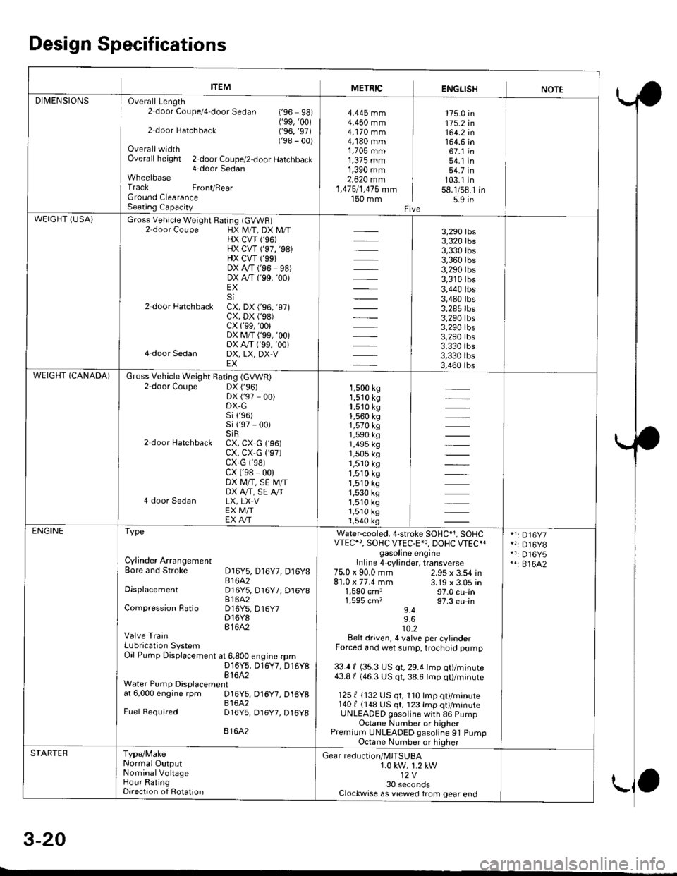
Design Specifications
ITEMMETRICENGLISHNOTEDII/IENSIONS Overall Length2 door Coupe/4 door Sedan (,96 98)('99,'�00)2 door Hatchback (,96, ,97)
('98 - 00)OverallwidthOverall height 2 door Coupe/2 door Hatchback4-door SedanWheelbase
I Track FronvRearGround ClearanceSeatiog Capacity
4,445 mm4,450 mm4,170 mm4,180 mm1,705 mm1,375 mm1,390 mm2,620 mm1,475/1,415 mm150 mm
175.0 in115.2 in164.2 in164.6 in67.1 in54.1 in54.7 in103.1 in58.1/58.15.9 in
WEIGHT (USA)Gross Vehicle Weight Raring (GVWR)2 door Coupe HX M/T, DX M/THX CVI ('96)HX CVT ('97,'98)HX CVT ('99}DX A,/T (96 98,DX A"/T ('99, '00)
EXSi2 door Hatchbacl CX. DX r'96, 97,cx, DX ('98)cx (,99, ,00)
DXM/Ti'99,00iDX A/T ( 99, 00,4 door Sedan DX, LX, DX-VEX
3,290 tbs3,320 tbs3,330 tbs3,360 rbs3,290 rbs3,310 tbs3,440 tbs3,480 tbs3,285 tbs3,290 tbs3,290 tbs3,290 tbs3,330lbs3,330 tbs3,460 tbsWEIGHT (CANADA)Gross Vehicle Weight Bating (GVWR)2-door Coupe DX ('96)DX ('97 00)DX-Gsi 1,96)si ('97 - 00)siR2 door Hatchback CX, CX,G ('96)cx, cx,G 1,97)cx-G (,98)
cx ('98 00)DX M/T, SE M/IDX A,/T, SE A,/T4 door Sedan LX, LX VEX M/IEX A/T
1,500 ks1,510 kg1,510 kg1,560 kg1,570 kg1,590 ks1,495 kg1,505 kg1,510 ks1,510 ks1,510 kg1,530 kg1,510 kg1,510 ks1,540 ksENGINEType
Cylinder ArrangementBore and Stroke D16Y5, D16Y7, Dt6y8B 1642DisplacementD16Y5, D16Y7, Dl6Y881642Compression Ratio D16Y5, D16y7D16Y8816A2Valve TrainLubrication SystemOil Pump Displacement at 6,800 engine rprnD16Y5, D,l6Y7, D16Y881642Water Pump Displacementat 6,000 engine rpm 016Y5, D16Y7, D16y8816A2Fuel Required D16Y5, D16Y7, D16y8
816A2
Water-cooled, 4-stroke SOHC*1, SOHCVTEC"', SOHC WEC.E'3, DOHC VTEC{gasoline engineInline 4 cylinder, transverse2.95 x 3.54 in3.19 x 3.05 in97.0 cu-in97.3 cu in9.49.610.2Belt driven, 4 valve per cylinderForced and wet sump, trochoid pump
33.4 f (35.3 US qt, 29.4 lmp qt)/minute43.8 | (46.3 US qt, 38.6 lmp qt)/minute
125 { {132 US qt, 110 lmp qt}/minute140 f {148 US qt, 123 lmp qt}/minuteUNLEADED gasoline with 86 PumpOctane Number or higherPremium UNLEADED gasoline 91 PumpOctane Number or higher
75.0 x 90.0 mm81.0 x 77.4 mm1,590 cm31,595 cm3
*1: D16Y7*': D16Y8*3: D16Y5*': 816A2
STARTEBType/MakeNormal OutputNominalVohageHour RatingDirection of Rotation
Gear reduction/MITSUBA1.0 kw, 1.2 kw12V30 secondsClockwise as viewed from gear end
5-Z.V
-
Page 101 of 2189
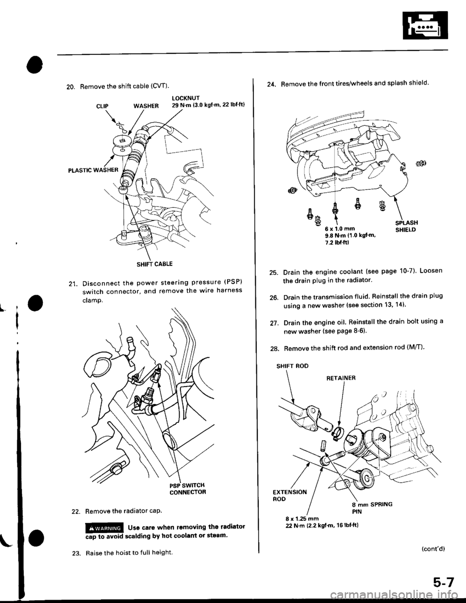
20. Remove the shift cable (CVT)
WASHER
Pt-Aslc
21. Disconnect the Power
switch connector, and
cramp.
LOCKNUT29 N.m {3.0 kgf m,22lbf'ft}
steering pressure (PSP)
remove the wire harness
CLIP
ll
I
Remove the radiator caP.
!!!@ usa care when l€moving the tadiator
Ap to avoid scalding by hot coolant or steam'
Raise the hoist to full height.
SHIFT CABLE
(cont'd)
25.
26.
27.
24. Remove the front tires/wheels and splash shield.
u x l.u mm SHIELD9.8Nm(1 0 kqt'm,
7.2lbf.ftl
Drain the engine coolant (see page 10-7). Loosen
the drain plug in the radiator.
Drain the transmission fluid Reinstall thedrainplug
using a new washer (see section 13, 14).
Drain the engine oil. Reinstall the drain bolt using a
new washer (see page 8-6).
28. Remove the shift rod and extension rod (M/T)
SHIFT ROD
EXTENSIONROD
8 x 1.25 mm22 N.m t2.2 kgf'm, 't6lbtft)
ER
6x1.0mm
Page 148 of 2189
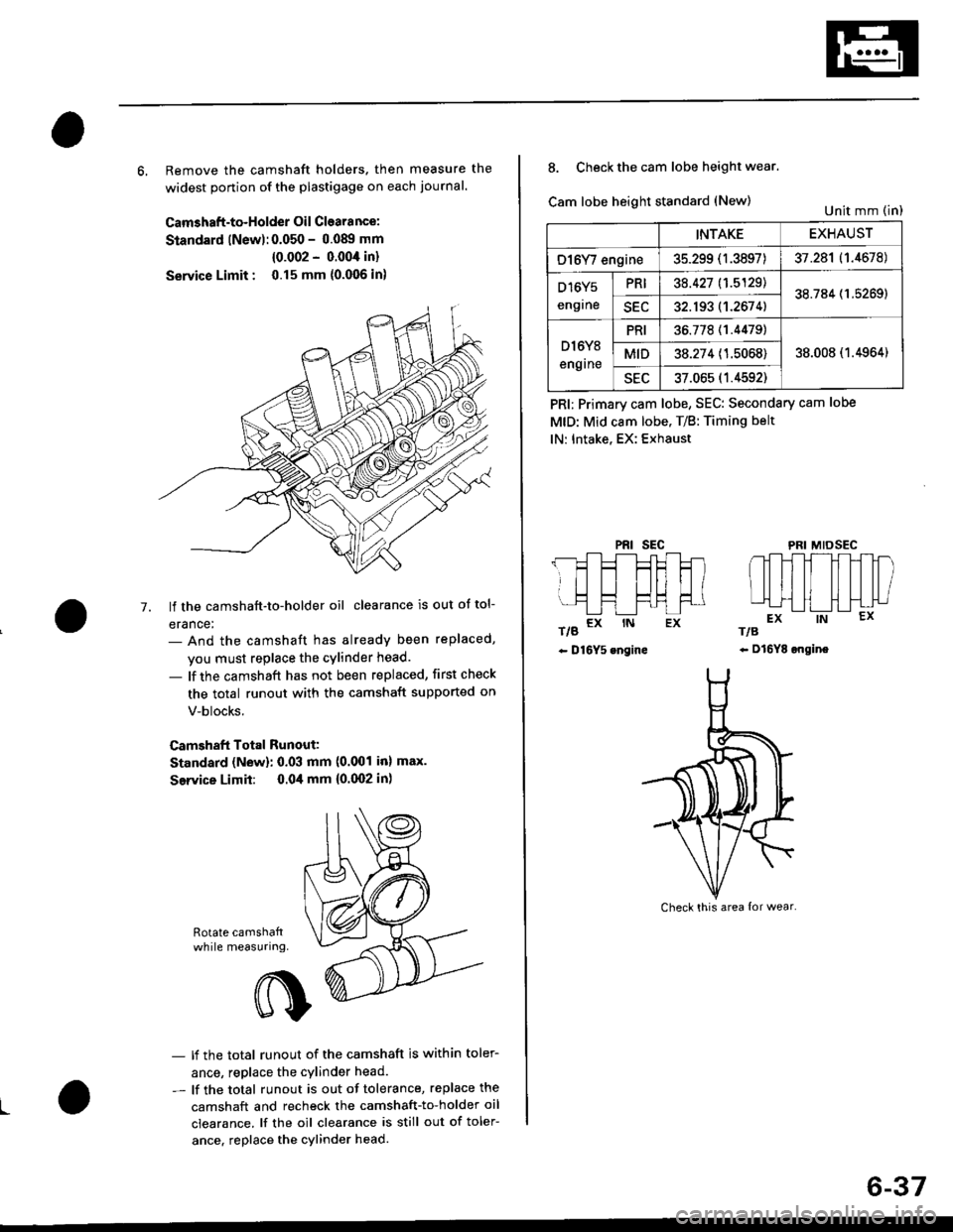
6, Remove the camshaft holders. then measure the
widest ponion of the plastigage on each journal.
Camshaft-to-Holder Oil Clearance:
Standard lNew):0.050 - 0.08!t mm
{0.002 - 0.004 in}
Service Limit : 0.15 mm {0.006 in)
lf the camshaft-to-holder oil clearance is out ot tol-
erance:- And the camshaft has already been replaced,
you must replace the cylinder head.
- lf the camshaft has not been replaced, first check
the total runout with the camshaft supported on
V-blocks.
Camshaft Total Runout:
Standard (New): 0.03 mm (0.001 inl max.
Service Limit: 0.04 mm {0.(X)2 in)
-7.
Rotate camshattwhile measuring.
L
- lf the total runout of the camshaft is within toler-
ance, replace the cylinder head.
- lf the total runout is out of tolerance, replace the
camshaft and recheck the camshaft-to-holder oil
clearance. lf the oil clearance is still out of toler-
ance. replace the cylinder head.
INTAKEEXHAUST
O16Y/ engine35.299 (1.3897)37.281 (1.4678)
D16Y5
engrne
PRI38.427 11.5129138.784 (1.5269)
SEC32.193 (1.2674)
D l6Y8
engrne
PRI36.77811.44791
38.008 (1.4964)MID38.274 (1.5068)
sEu37.065 (1.4592)
8. Check the cam lobe height wear.
Cam lobe height standard (New)
t/g a* rN Ex
- D16Y5 engine
PRI; Primary cam lobe, SEC: Secondary cam lobe
MtD: Mid cam lobe. T/B: Timing belt
lN: Intake, EX: Exhaust
PRIsEcMIDSEC
rts
- Dl6YE ongine
Unit mm (in)
Check this area {or wear.
6-37