Page 110 of 2189

Engine Removal/lnstallation
Installation (cont'd)
Except CVT:
12 x 1.25 mm64 N.m (6.5 kgd.m,
Tighten the bolts/nut on the left front mount in thenumbered sequence shown {O - @).
(t 12 x 1.25 mm83 N'm (8.5 kgf.m,61 tbt.trl
/+4 N.m 14.5 kgf.m,33 lbt.trl
O 12 r 1.25 mm59 N.m 16.0 kgt.m,43 tbt.rtlSeplace.
5-16
\
7. Perform the following:
. Clean the areas where the driveshaft(s) and theintermediate shaft contact the transmission (dif_ferential) thoroughly with solvent or carburetorcteaner, and dry with compressed air.. Check that the set rings on the ends of the drive_shaft and intermediate shaft click into place.CAUTION: Use new set rings,. Adjust the shift cable (see section 14).. Adjust the throttle cable (see section 11).. Adjust the cruise control cable (see section 23).. Refill the engine with engine oil (see page 8-6).. Refill the transmission with fluid (see section 13,14).
. Refill the radiator with engine coolant (see page10-7).
. Bleed air from the cooling system with the heatervalve open (see page j0-7).
. Clean the battery posts and cable terminals withsandpaper, assemble them, then apply grease toprevent corrosaon.. Inspect for fuel leakage (see section j l).After assembling the fuel line, turn on l) the igni_tion switch (do not operate the starter) so that thefuel pump runs for approximately two secondsand the fuel line pressurizes. Repeat this opera_taon two or three times, then check for fuel leak_age at any point in the fuel line,
Page 128 of 2189

Timing Belt
Illustrated lndex
NOTE:
. Refer to page 6-20 for how to position the crankshaft and pulley before installing the belt.
. Mark the direction of rotation on the belt before removing.
a Do not use the upper cover and lower cover for storing removed items,
. Clean the upper cover and lower cover before installing.
. Replace the ca mshaft seals and cra n kshaft sea ls if there is oil leakage.
. Refer to page 6-16 before installing the timing belt.
CYLINDER HEADCOVERReler to page 6-46when installing.
HEAD COVEB GASKETReplaco when l6akin9,domaged or deteriorated.Apply liquid gasket at
th€ lour corners of thetecessos.
d
@
TIMING BELTInspection, page 6-18Adjustment, page 6-18Removal, page 6-19Installation. page 6-20
I x 1.25 mm3t N.m {3.8 kgf'm, 27 lbfftl
Apply engine oilto the bolt
thleads.
CRANKSHAFT SPEED FI.UCTUATION
lcr(Fl sENsoRReplacement, Page 6-22
UPPER COVEB
lnstallwithsurface facing in.
TIMING BELTDRIVE PULLEYReplacement, page 6_16
6x1.0mm9.8 N'm 11.0 kgt m,7.2 tbf.ft)NUBBER SEALSReplace when damagedor deledorated.
LOWER COVER
FUBBERPLUG
CRANKSHAFT PULLEYReplacement, page 6'16
PULLEY BOLTlil x 1.25 mm20 N.m 12.0 kgt.m,14 lbt'ft) + 90"Replacement, page 6'16Do not us6 an impactwrench when installing.
x 1.0 mmBOLT o-RING10 x 1,25 mm Reolace.14 N.m {,1.5 kgt m, 33 lbt ftl
6x1.0mmt2 N.m 11.2 kgf'm,8.7 tbt f0
9.E N'm (1.0 kgt.m,?.2 tbf.ftl\.-,o
6-17
Page 134 of 2189

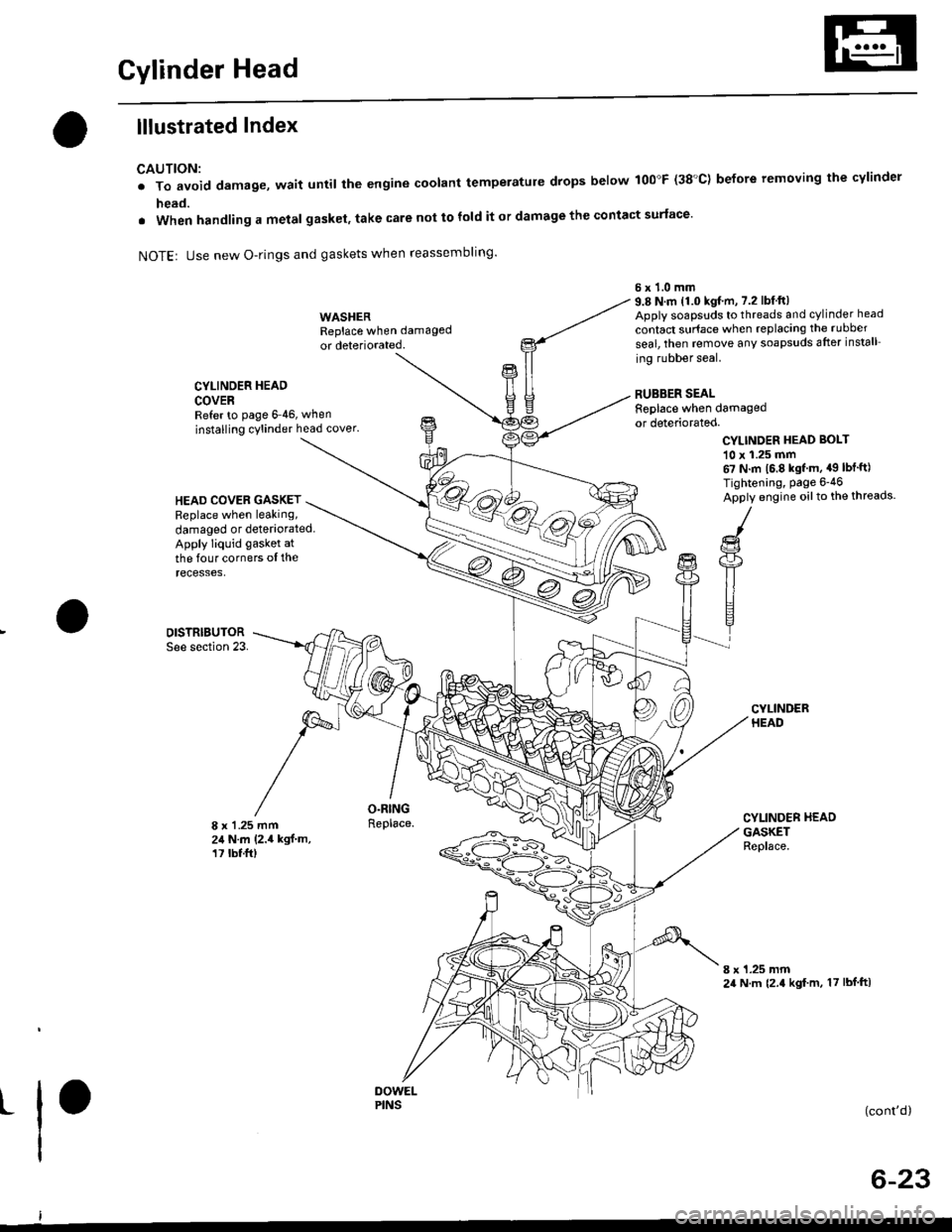
Gylinder Head
lllustrated Index
CAUTION:
. To avoid damage, wait until the engine coolant temperatule drops below 100"F (38'C) before removing the cylinder
head.
. When handling a metal gasket, take care not to fold it or damage the contact surface'
NOTEr Use new O-rings and gaskets when reassembling'
CYLINDER HEAD
COVERRefer to page 6 46, when
installing cylinder head cover.
WASHERReplace when damaged
or deteriorated.
O.RINGReplace.
6x1.0mm9.8 N.m 11.0 kgf.m, 7.2 lbfft)Apply soapsuds to threads and cylinder head
contact surface when replacing the rubber
seal, then temove any soapsuds after install
ing rubber seal.
RUBBER SEALReplace when damagedor deteriorated.
CYLINDER HEAD BOI-T
10 x 1.25 mm67 N.m 16.8 kgf m, a9 lbt'ft)
Tightening, Page 6-46
Apply engine oilto the threads.HEAD COVEB GASKETReplace when leaking,
damaged or deteriorated.Apply liquid gasket at
the four corners ol therecesses,
DISTRIBUTORSee section 23.
8 x 1 .25 mm24 N.m (2.4 kgf.m,17 tbt.ft)
CYLINDER HEADGASKETReplace.
8 x 1.25 mm24 N.m {2.4 kgf m, 17 lbf ftl
t(cont'd)
6-23
PINS
Page 170 of 2189

Timing Belt
lllustrated Index
NOTE:
. Refer to page 6-59 for positioning crankshaft and pulley before installing belt.. Mark the direction of rotation on the belt before removino.a Do not use the middle cover and lower cover for storing r'emoved items.. Clean the middle cover and lower cover before installation.
WASHER
I
Replace when damagedor deteriorated.CAP NUTx 1,0 mm9.8 N.m lr.0 kgf.m, 7.2lbtftl
CYLINDERHEAD COVERRefer to page 6-86when installing.
HEAD COVER GASKETReplace when leaking,damaged or deteriorated.Apply liquid gasket atthe four corners ol therecesses,
TIMING BELTInspection, page 6-61Adjustment, page 6-61Replacement, page 6-62
I
6 x '1.0 mm9.8 N.m {1.0 kgf.m, 7.2 lbt.ftl
l0 x 1.25 mm5a N.m {5.5 kgl.m,40 tbt ftt
MIDDTE COVER
6 x 1.0 mrn9.8 N.m {1.0 kgf.m,7.2 tbt-ltl
8 x 1.25 mmN.m {5.7 kgt.m,41 tbt fr)
6x1.0mmN.m 11.0 kgf.m,7.2 tbt.ft'l
PULLEY BOLT14 x 1.25 mm177 N.m {18.0 kgf.m. 130 tbt.ft}Beplacement, page 6-59Do not use an impactwrench when installing.
TIMING BELTDRIVE PULLEY
Installwith concavesurtace facing out.Remove any oil and clean.
LOWERCOVER
CRANKSHAFT PULLEYReplacement, page 6-59
- -o
6-60
Replacement, page 6-59
Page 175 of 2189
Cylinder Head
lllustrated Index
CAUTION:
. To avoid damaging the cylinder head, wait until the engine coolant tempsraturo drops below 100"F (38"C1 bofote
removing it,
. when handling a metal gasket, take caro not to fold the gaskot or damage the contact surface of the gasket.
NOTE: Use new O-rings and gaskets when reassembling.
CYLINDER HEAO
PLUGReplace.
)@
DISTRIBUTOR
8 x 1 ,25 mm
27 N.m P.E kgl m.
20 tbf.foApply engine oil to
the threads.
cr.rMp.S
CAMSHAFT A"o''*t*'; wes@
OIL SEALReplace.
6 x l,omm9.8 N'm tl.0 kgt'm,7.2lbf ft)
RUBBER SEALReplace when damaged
or detedorated.
6x1.0mm9.8 N.m (1.0 kgf'm,
7.2 rbnftl
fi%
IGNMONWIRE COVER
CYLINOER HEAD
COVERRefer to page 6-86
when installing
HEAD COVER GASKETReplace when leaking, damaged
or deteriorated.Apply liquid gasket at thecorners of the recesses, Page 6-86
8 x 1,25 mm24 N.m {2.4 kgf'm,
1? tbf.ftl
EXHAUST
10 x 1.25 mm56 N.m (5.7 kgf m,,r1 lbl.ft)
(cont'd)
6-65
Page 221 of 2189

Crankshaft
Installation (cont'd)
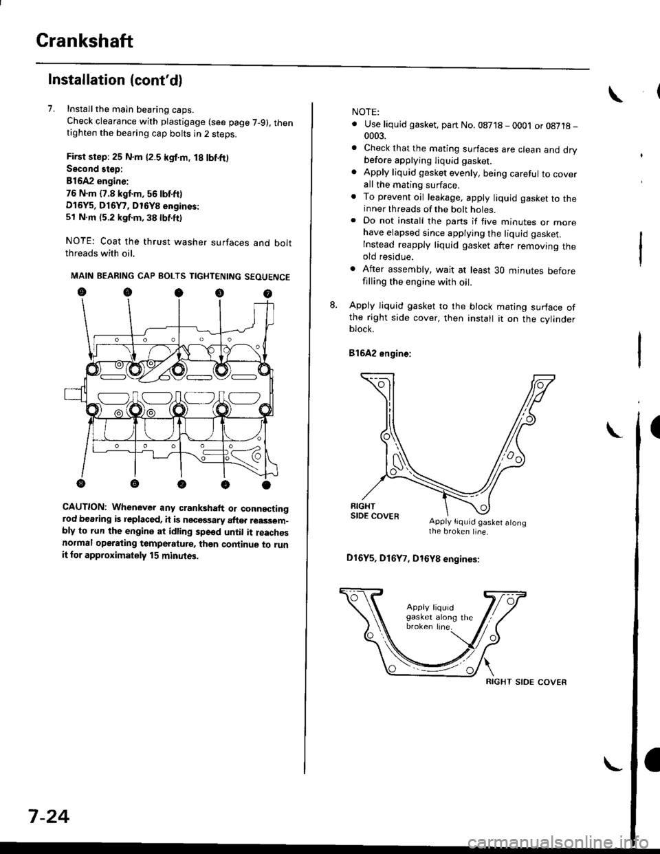
7. Installthe main bearing caps.
Check clearance with plastigage (see page 7-9), thentighten the bearing cap bolts in 2 steps.
First step: 25 N.m {2.5 kgf.m, 18 lbf.ft)
Second stop:
B1642 engine:
76 N.m {7.8 kgf.m, 56 lbf.ft)
D16Y5, D16Y7, D16Y8 engines:
51 N.m (5.2 kgf.m, 38 lbf.ft)
NOTE: Coat the thrust washer surfaces and boltthreads with oil.
MAIN BEARING CAP BOLTS TIGHTENING SEOUENCE
oocoo
CAUTION: Whenever any crankshaft or connectingrod bearing is replaced, it is necGssary after reassom-bly to run the engine at idling spe6d until it reachesnormal operating temperature, than continue to runit for approximately 15 minutos.
:V fr\-/.---\-/.-
7-24
NOTE:
. Use liquid gasket, part No. 08718 - 0001 or08718-0003.
. Check that the mating surfaces are clean and drybefore apptying liquid gasket.
. Apply liquid gasket evenly, being careful to coverall the mating surface.. To prevent oil leakage, apply liquid gasket to theinner threads of the bolt holes.. Do not install the parts if five minutes or morehave elapsed since applying the liquid gasket.
Instead reapply liquid gasket after removing theold residue.
. After assembly, wait at least 30 minutes beforefilling the engine with oil.
L Apply liquid gasket to the block mating surface ofthe right side cover, then install it on the cylinderblock.
Bl6A2 engine;
Apply tiquid gaslet alongthe broken line.
D16Y5, D16Y7, D16Y8 engines:
RIGHT SIDE COVER
Page 224 of 2189

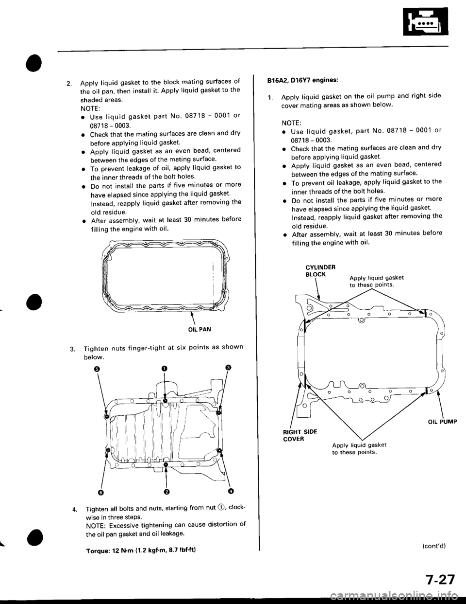
2. Apply liquid gasket to the block mating surfaces of
the oil pan, then install it. Apply liquid gasket to the
shaded areas.
NOTEI
. Use liquid gasket part No. 087 18 - 0001 or
08718 - 0003.
. Check that the mating surfaces are clean and dry
before apPlying liquid gasket.
. Apply liquid gasket as an even bead, centered
between the edges ol the mating surface'
. To prevent leakage of oil, apply liquid gasket to
the inner threads of the bolt holes
. Do not install the parts if five minutes or more
have elapsed since applying the liquid gasket
lnstead, reapply liquid gasket after removing the
old residue
. After assembly, wait at least 30 minutes before
filling the engine with oil.
Tighten nuts finger-tight
below.
OIL PAN
at six points as shown
I
3.
4. Tighten all bolts and nuts, starting from nut @, clock-
wise in three steps.
NOTE: Excessive tightening can cause distortion of
the oil pan gasket and oil leakage.
Torque: 12 N'm {1.2 kgt'm,8.7 lbf'ft|
816A2, D16Y7 engines:
1. Apply liquid gasket on the oil pump and right side
cover mating areas as shown below.
NOTE:
. Use liquid gasket, part No. 08718 - 0001 or
08718 - 0003.
. Check that the mating surfaces are clean and dry
before applying liquid gasket
. Apply liquid gasket as an even bead, centered
between the edges ol the mating surface'
. To prevent oil leakage, apply liquid gasket to the
inner threads of the bolt holes
. Do not install the parts if five minutes or more
have elapsed since applying the liquid gasket
Instead, reapply liquid gasket after removing the
old residue.
. Aftel assembly, wait at least 30 minutes before
filling the engine with oil.
CYLINDERELOCKApply liquid gasket
to these pornts-
Apply liquid gasket
to these pornts.
(cont'd)
7 -27
Page 225 of 2189
Oil Pan
lnstallation (cont'dl
Install the oil pan gasket and oil pan
NOTE:
a Use a new oil pan gasket.. Install the oil pan no more than five minutesafter applying liquid gasket.
816A2 engine:
OIL PANGASKETR€place.
Apply liquidgasKet tothese points.
Apply liquid gaskerto these points.
OIL PANGASKETBeplace.
7-28
\
3, Tighten the bolts and nuts finger tight at six pointsas shown below.
Tighten all bolts and nuts, starting from nut O.clock wise in three steps.
NOTE: Excessive tightening can cause distortion ofthe oil pan gasket and oil leakage.
Torque: 12 N.m {1.2 kgf.m, 8.7 lbf.ft)
4.