Page 193 of 1002

Downloaded from www.Manualslib.com manuals search engine
Cylinder Head and Valvetrain
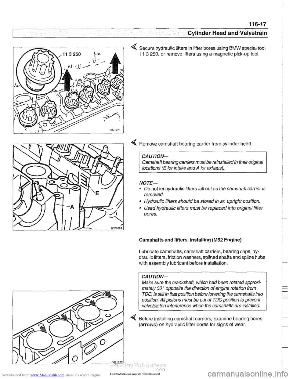
4 Secure hydraulic lifters in lifter bores using BMW special tool
11 3 250, or remove lifters using a magnetic pick-up tool.
4 Remove camshaft bearing carrier from cylinder head.
CA UTION-
Camshaftbearing carriers must be reinstalledin their original
/ locations (E for ir;fal
NOTE-
Do not let hydraulic lifters fall out as the camshaft carrier is
removed.
Hydraulic lifters should be stored in an upright position.
Used hydraulic lifters
must be replaced into original lifter
bores.
Camshafts and lifters, installing
(M52 Engine)
Lubricate camshafts, camshaft carriers, bearing caps, hy-
draulic liflers, friction washers, splined shafts and spline hubs
with assembly lubricant before installation.
Make sure
the cranltshaft, which had been rotated approxi-
mately
30" opposite the direction of engine rotation from
TDC, is still in thatposition before lowering the
camshaffs into
position. All pistons must be out of TDC position to prevent
valve/piston interference when the camshalts are installed.
Before installing camshaft carriers, examine bearing bores
(arrows) on hydraulic lifter bores for signs of wear.
Page 201 of 1002

Downloaded from www.Manualslib.com manuals search engine
Cylinder Head and Valvetrain
NOTE-
The camshaft bearing caps are coded with a letter and a
number. For example, "A
1" is the first exhaust camshaft
bearing cap
at the front of the engine, and "El "is the intake
camshaft bearing cap at the front of the engine.
-. -
The camshafts are stamped with a code letter - "E for the
intake side and
'X" for the exhaust side.
"E is for Einlap. (German for intake) and 'XA7s for Auspuff.
(German for exhaust).
- Repeat procedure for exhaust camshaft
< Secure hydraulic lifters in lifter bores using BMW special tool
11 3 250, or remove lifters using a magnetic pick-up tool.
I CAUTION-
Used liydraulic lifters must be reinstalled in original lifter
1 bores.
4 Remove lower camshaft bearing carriers from cylinder head.
CAUTION- Camshaft bearing carriers must be reinstalled in their original
locations
(E for intalce and A for exhaust).
NOTE- Do not allow hydraulic lifters to fall out of camshaft carriers.
Hydraulic lifters should be stored in an upright position.
Camshafts and lifters, installing (M52TU and M54 engine)
Lubricate camshafts, camshaft carriers, bearing caps, hy-
draulic lifters, friction washers, splined shafts and
spline hubs
with assembly
lubricant before installation.
CAUTION-
Make sure the crankshaft, which had been rotated approxi-
mately
30" opposite the direction of engine rotation from
TDC, is
stillin thatposition before lowering the camshafts into
position. Allpistons must be out of
TDCposition to prevent
valve/piston inteiference when the carnshafis are installed.
- Lift timing chain and place exhaust cam onto exhaust cam-
shaft carriers. Place
intake camshaft on camshaft carrier.
Page 232 of 1002

Downloaded from www.Manualslib.com manuals search engine
1 16-56
Cylinder Head and Valvetrain
This section covers valve removal and reconditioning, includ-
ing valve guides, seats, springs, and valve stem oil seals.
Valves, leak test
To test the valves for leakage, the cylinder head must be dis-
assembled with camshafts and camshaft carriers removed.
With valve assemblies and spark plugs installed, place the
cylinder head on a workbench with the combustion chamber
facing upward. Fill each combustion chamber with a thin non-
flammable liquid. After fifteen minutes,
check the level of the
fluid. If the fluid level in any cylinder drops, that cylinder is not
sealing properly.
Valves, removing and installing
- Remove cylinder head as described in 113 Cylinder Head
Removal and Installation.
CAUTIOI\C
(M52 TU/M54 engines only) Do not let the hydraulic lifters
fall out as the camshaft carrier is removed. Special suction
cups are available from
BMW to hold the hydraulic lifters in
place during carrier removal.
* Hydraulic cam lifters should be stored m an uprfght po-
sition. If necessary, use a magnetic tool to
aidin remov-
al of the lifters.
- Remove valves using a valve spring compressor.
CAUTIOI\C
Label each valve assembly as it is removed so it can be in-
stalled in its original position.
-
- Remove and discard valve stem oil seals from valve guides.
See Valve stem oil seals later in this section.
- Valve installation is reverse of removal. Remove carbon de- - -
posits from the valves using a wire brush or wire wheel. -
-
Valve specifications are listed in Table c. Valve specifica-
tions.