1997 BMW 540i replacing
[x] Cancel search: replacingPage 54 of 1002

Downloaded from www.Manualslib.com manuals search engine
020-22 Maintenance
1
- Installation is reverse of removal, bearing in mind the
following:
Lightly lubricate new
spark plug threads with
copper-based anti-seize compound.
Thread plugs into cylinder head by hand to prevent
cross-threading.
. Be sure to reinstall and tighten coil grounds.
Tightening torque Spark plug
to cylinder head 25 Nm (18 It-lb)
Interior ventilation microfilter, replacing
Two interior ventilation microfilters are used, one on each
side of the engine compartment at the fire wall.
< To replace the microfilter, unclip the wire fastener and
remove the cover.
Lift out the filter, and replace. Left side shown; right is
similar.
Replace cover and clip wire fastener to retain cover.
Battery, checking, cleaning, and replacing
The battery Is located in the right side of the luggage compart-
ment. Simple maintenance of the battery and its terminal
connections will ensure maximum starting periormance,
especially in winter when colder temperatures reduce battery
power.
Battery cables should be tight. The terminals, cable clamps
and battery case should be free of the white deposits that
indicate corrosion and acid salts. Even a thin layer of dust
containing conductive acid salts can cause battery discharge.
Page 56 of 1002
Downloaded from www.Manualslib.com manuals search engine
020-24
Maintenance
tions. In general, replacement batteries should always be
rated equal or higher than the original battery.
The battery is held in place by a single hand screw and plate.
A secure battery hold-down is important in order to prevent
vibrations and road shoclt from damaging the battery.
CAUTION-
Prior to disconnecting the baitem read the battery discon-
nection cautions given in
001 General Cautions and
Warnings.
NOTE-
Always disconnect the negative (-) cable first, and connect
it last. While changing the battery, clean away any corro-
sion in or around the battery tray
More battery and charging system information is in 121
Battery, Alternator, Starter.
Brake fluid, replacing
Brake fluid absorbs moisture easily, and moisture in the fluid
affects bralte performance and reliability. This is why
BMW
strictly recommends replacing the bralte fluid every two
years. When replacing or adding bralte fluid, use only new
fluid from previously unopened containers. Do not use brake
fluid that has been bled from the system, even
if it is brand
new. Use only DOT
4 brake fluid.
NOTE-
See 340 Brakes for brake fluid flushing procedures.
Brake pad 1 rotor wear, checking
Disc brakes are fitted at all four wheels. Although the brakes
are equipped with a brake pad warning system, the system
only monitors one wheel per axle. Pad thickness should be
checked whenever wheels are off or brake
worlt is being
done.
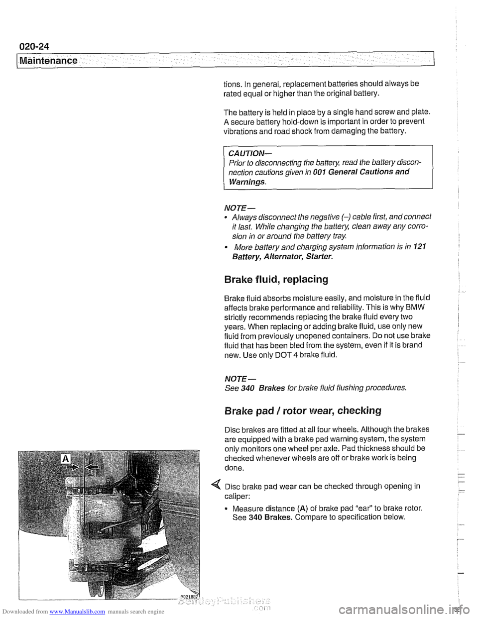
4 Disc brake pad wear can be checked through opening in
caliper:
Measure distance
(A) of brake pad "eai' to bralte rotor.
See
340 Brakes. Compare to specification below.
Page 59 of 1002

Downloaded from www.Manualslib.com manuals search engine
.-. -
Maintenance
Drive axle joint
(CV joint) boots, inspecting
CVjoint protective boots must be closely inspected forcracks
and any other damage that will allow contaminants to get into
the joint.
If the rubber boots fail, the water and dirt that enter
the joint will quickly damage it.
NOTE-
Replacement of the CVjoint boots and inspection of the
joints are described
in 331 Final Drive.
Exhaust system, inspecting
Exhaust system life varies widely according to driving habits
and environmental conditions. If short-distance driving pre-
dominates, the moisture and condensation in the system will
not fully dry out. This will lead to early corrosion damage and
more frequent replacement.
Scheduled maintenance of the exhaust system is limited to
inspection:
* Check to see that all the hangers (arrow) are in place and
properly supporting the system and that the system does
not strike the body.
Check for restrictions due to dents or
kinlts,
Check for weakness or perforation due to rust.
NOTE-
Alignment of the system and the location of the hangers are
described in
180 Exhaust System.
Fuel filter, replacing
The fuel filter is located beneath the center of the car, approx-
imately under the driver's seat.
A protective cover must be
removed to access the filter.
4 Fuel filter for M62 engine (arrow)
- Disconnect battery negative (-) cable
CAUTIOI\C
Disconnecting the battery cables may erase fault codes
stored
in engine control module memory.
WARNING -
Fuel will be expelled forcibly when the filter is removed. Do
notsmoke or work near heaters orother fire hazards. Keep a
fire extinguisher handy
Page 60 of 1002

Downloaded from www.Manualslib.com manuals search engine
020-28
1 Maintenance
- When replacing fuel filter:
Use appropriate hose clamping device to clamp off filter
inlet and outlet hoses to lessen fuel spillage.
Loosen center clamping bracket and hose clamps on
either end of filter.
Note arrow or markings indicating direction of flow on
new filter.
Install new filter using new hose clamps
- Drain fuel filter from inlet side into a container and inspect
drained fuel.
Checlc for rust, moisture and contamination.
I - I < If fuel filter is equipped with fuel pressure regulator:
I 2 / Remove vacuum hose (1)
Pull out locking clip (2).
- Remove fuel pressure regulator (3).
Install pressure regulator in new filter.
Clean thoroughly around the filler connections before
removing them.
After assembly, check filter connections carefully for
I
I lealcs before installing cover.
NOTE- ~-
Additional informarion about the fuel filler assembly is in 160
Fuel Tank and Fuel Pump.
Fuel tank and fuel lines, inspecting
lnspectthe fuel tank, fuel lines, and fuel system fordamage or
lealts. Checlc for fuel lealts in the engine compartment or fuel
odors in the passenger compartment. Check for any evapora-
tive emissions hoses that may have become disconnected,
checking carefully at charcoal canister and evaporative emis-
sions purge system. See
130 Fuel Injection and 160 Fuel
Tankand Fuel Pump for component locations and additional
information.
WARNING-
When checlcing for fuel leal(s, the engine must be cold. A hot
exhaust manifold or exhaust system could cause the fuel to
ignite or explode causing serious personal injury Ventilate
the work area and clean up spilled fuel immediately.
Page 65 of 1002

Downloaded from www.Manualslib.com manuals search engine
ing at the finish when it is wet. If the water coats the paint in
smooth sheets instead of forming beads that roll off, a new
coat of wax is needed. Waxshould not be applied to black trim
pieces, rubber, or other plastic parts.
Windshield wiper blade maintenance
Common problems with the windshield wipers include streak-
ing or sheeting, water drops afler wiping, and blade chatter.
Streaking is usually caused when wiper blades are coated
with road
film or car wash wax. Clean the blades using soapy
water.
If cleaning the blades does not cure the problem, they
should be replaced. BMW recommends replacing the wiper
I blades twice a year, before and after the cold season.
I
< To replace wiper blade, depress retaining tab (arrow) and
slide blade out of arm.
I - Checlc tension spring that forces wiper against glass. Re-
place wiper arm if spring tension is weak.
Drops that remain behind after wiping are caused by oil, road
film, or diesel exhaust coating the windshield. Use an alcohol
or ammonia solution or a nonabrasive cleanser to clean the
windshield.
Wiper blade chatier may be caused by dirty or worn blades,
by a dirty windshield, or by bent or twisted wiper arms. Clean
the blades and windshield as described above.
Adjusithe
wiper arm so that there is even pressure along the blade, and
so that the blade is perpendicularto the windshield at rest. Lu-
bricate the wiper linkage with a light oil. The
linkage is located
under the hood on the driver's side. If the problem persists,
the blades are excessively aged or worn and should be re-
placed. See
61 1 Wipers and Washers for more information.
Page 177 of 1002

Downloaded from www.Manualslib.com manuals search engine
11 6 Cylinder Head and Valvetrain
........................... General ............................ 1 16-2 Valves 116-56
.................... Special Tools ........................ 11 6-2 Valves. leak test 11 6-56
......... Valves. removing and installing 11 6-56 Cylinder Head ..................... .I1 6.5 ....................... Valve guides 11 6-57
Valves. leak test ...................... 11 6-6
Valve stem oil seals .................. 11 6-58 ...... ..""""."""ll 6.6 Valveseats ........................ 116-59 Hydraulic lifters, checking and replacing .. .I1 6-7 Valve ....................... 6-60 . .
Camshaft andLifter Removal
and Installation
.................... 11 6-1 1
Camshaft and lifter removal and
installation
(M52 engine) ............. .I1 6.12
Camshaft and lifter. removal and
installation (M52
TU and M54 engine) .... 11 6-1 9
Double VANOS timing chain components
. 11 6-28
Camshaft removal and installation
(M62 engine)
....................... 11 6-39
Page 183 of 1002

Downloaded from www.Manualslib.com manuals search engine
Cylinder Head and valvetrain1
Hydraulic lifters, checking and replacing
Self-adjusting hydraulic lifters (A) keep the valve clearances
within a limited working range. Hydraulic lifters are sealed
units and require no maintenance. Section view of camshaft
(6) and valve with conical valve spring (C) shown.
Under some circumstances, such as a cold start, the cam fol-
lowers may emit noise. Hydraulic lifter noise is usually a
high-
pitched tapping or chattering noise. In most instances, this is
considered normal as long as the noise goes away in a few
minutes (maximum
20 minutes). If the noise does not go
away, either the lifter is faulty or the oil pressure to the lifter is
low. Hydraulic lifter replacement requires that the camshaft
first be removed.
NOTE-
Before checking hydraulic lifters, male sure engine oil is
fresh and at the proper level.
Sticky lifters can be the result of
sludge build up in the cylinder head and lifters.
- Run engine until it reaches normal operating temperature.
Shut off engine.
- Working inside luggage compartment, disconnect negative
battery cable.
CAUTION-
Prior to disconnecting battery cable, read the baltery dls-
connection cautions given In 001 General Cautions and
Warnings.
Disconnecting the battery may erase fault
code(s)
stored in control module memory Check for fault codes
4 Remove left and right interior ventilation duct (left side
shown):
Release plastic locking tab
(A) or release loclting tabs on
top of duct (later models).
Rotate duct counterclockwise to
unloclt from bulithead and
remove (arrow).
Page 233 of 1002

Downloaded from www.Manualslib.com manuals search engine
-
- - . - Cylinder Head and Valvetrain -
Table c. Valve specifications
Valve head diameter
lntaite 33.0 mm 33.0 mm 35.0 mm
Exhaust
30.5 mm 30.5 mm 30.5 mm
Valve stem diameter
- Standard
Intake
6.0 mm .0.025 6.0 mm -O.o" .o.040 6.0 mm .0.025 .0,040
Exhaust 6.0 mm -0.0"0 -0.055 6.0 mm -0.040 .0,055 6.0 mm .0.040 .0,055
Valve stem diameter - Oversize 1 (identified on stem as Rl)
Intake 6.1 mm -0.025 .0.040 6.1 mm .0-025 .0,040 6.1 mm -O.o" .o,040
Exhaust 6.1 mm .O.O4O ..,,,, 6.1 mm -0.040 -0.055 6.1 mm -0.040 .0,055
Valve stem diameter - Oversize 2 (identified on stem as R2)
Intake 6.2 mm -O-OZ5 6.2 mm -0.025 .0.040 6.2 mm -0.025 .0,040
Exhaust 6.2 mm -0.040 -0.055 6.2 mm -0.040 .o.055 6.2 mm -O."o .o,055
Valve guides
BMW does not supply valve guides as replacement parts. If a
valve guide is excessively worn, it should be reamed to ac-
cept oversized
valve stems. Valve guide specifications are
listed in
Tabled. Valve guide specifications.
- Valve guides should be checked for wear using a new valve.
Be sure to thoroughly inspect the cylinder head to ensure
that it can be reused before reworking the guides.
NOTE-
International Organization for Standardization (1.30) toler-
ance classes are listed in Table c.
IS0 allowances are
based on nominal sizes and should be used to determine
proper fit. Most machine shops should have this informa-
tion available.
Replacement valve guides may be available through after-
market suppliers. Valve guide replacement requires spe-
cial tools and a press. It is also necessary to heat the
cylinder head and chill the valve guides when replacing the
guides.
BMW supplies oversize valves. See Table d. Valve guide
specifications for additional information.