Page 89 of 1002

Downloaded from www.Manualslib.com manuals search engine
- .. -.
-. Engine Removal and in=/
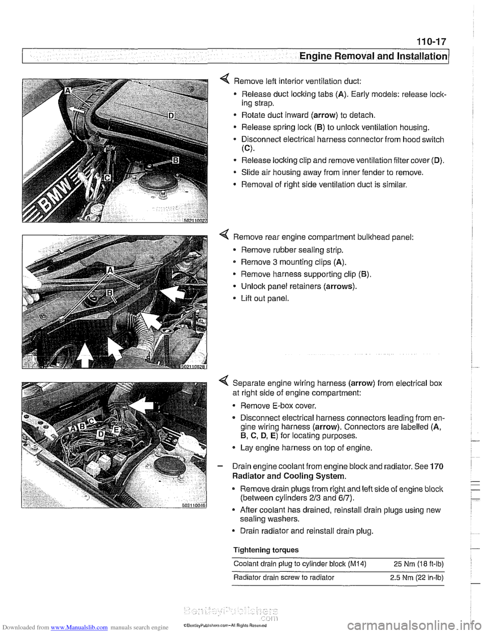
4 Remove left interior ventilation duct:
Release duct locking tabs (A). Early models: release
loclc
ing strap.
* Rotate duct inward (arrow) to detach.
Release spring
loclc (El) to unlock ventilation housing.
Disconnect electrical harness connector from hood switch
(C).
Release locking clip and remove ventilation filter cover (D).
Slide air housing away from inner fender to remove.
Removal
of right side ventilation duct is similar.
4 Remove rear engine compartment bulkhead panel:
Remove rubber sealing strip.
* Remove 3 mounting clips (A).
Remove harness supporting clip
(El).
Unlock panel retainers (arrows).
Lifl out panel.
< Separate engine wiring harness (arrow) from electrical box
at right side of engine compartment:
Remove E-box cover.
Disconnect electrical harness connectors leading from en-
gine wiring harness (arrow). Connectors are labelled (A,
El, C. D, E) for locating purposes.
Lay engine harness on top of engine.
- Drain engine coolant from engine block and radiator. See 170
Radiator and Cooling System.
Remove drain plugs from right and left side of engine
bloclc
(between cylinders 213 and 617).
Afler coolant has drained, reinstall drain plugs using new
sealing washers.
Drain radiator and reinstall drain plug.
Tightening
torques
Coolant drain plug to cylinder block (M14) 25 Nm (18 ft-ib)
Radiator drain screw to radiator 2.5
Nm (22 in-lb)
Page 119 of 1002

Downloaded from www.Manualslib.com manuals search engine
11 3-25
Cylinder Head Removal and Installation
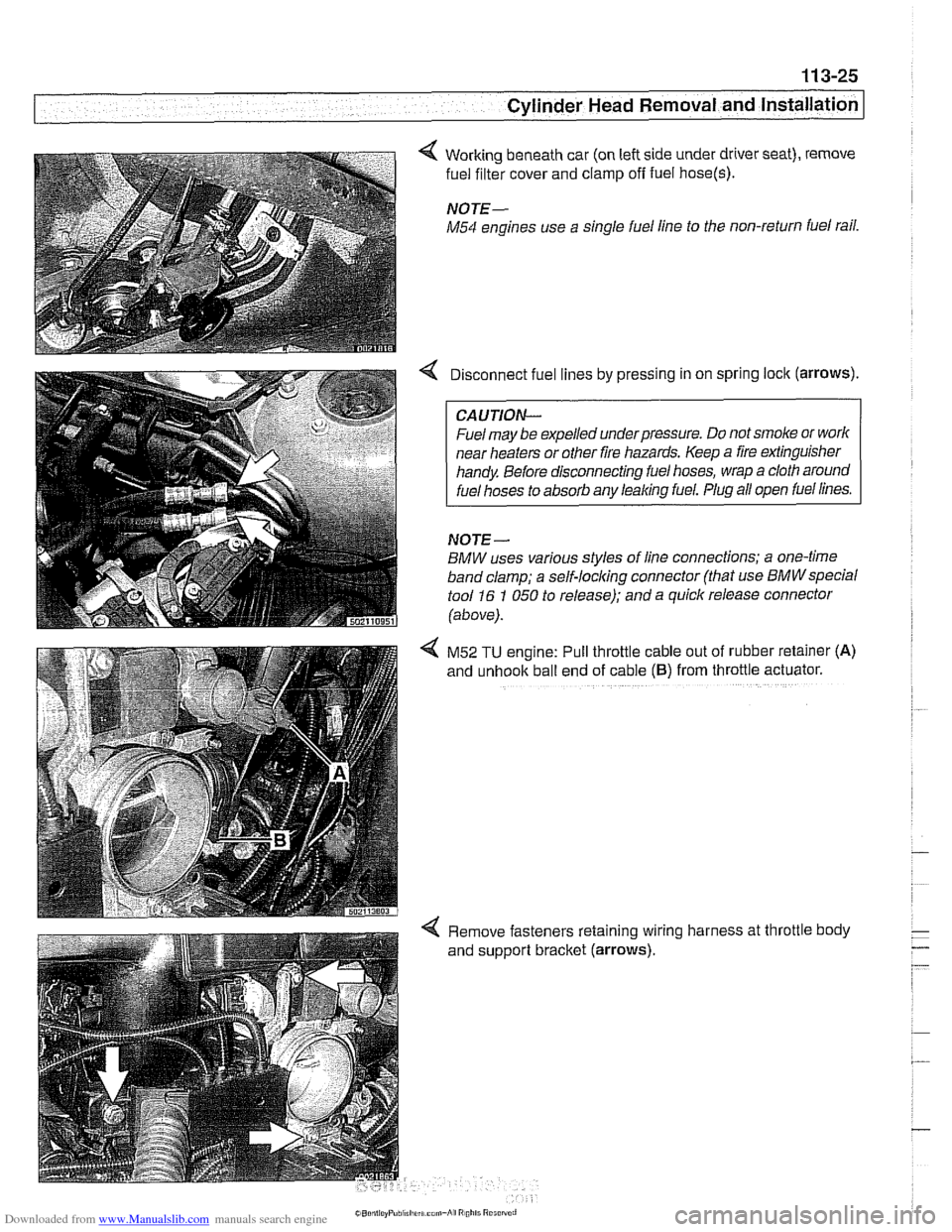
4 Working beneath car (on left side under driver seat), remove
fuel filter cover and clamp
off fuel hose(s).
NOTE-
M54 engines use a single fuel line to the non-return fuel rail.
Disconnect fuel lines by pressing in on spring lock (arrows).
CAUTION--
Fuel may be expelled underpressure. Do not smoke or worlc
near heaters or other fire hazards. Keep a fire extinguisher
handy Before disconnecting fuel hoses, wrap a cloth around
fuel hoses to absorb any leaking fuel. Plug all open fuel lines.
NOJE-
BMW uses various styles of line connections; a one-time
band clamp; a
self-locl(ing connector (that use BMWspecial
tool 16 1 050 to release); and a quick release connector
(above).
4 M52 TU engine: Pull throttle cable out of rubber retainer (A)
and unhook ball end of cable (6) from throttle actuator.
4 Remove fasteners retaining wiring harness at throttle body
and support bracket (arrows).
Page 153 of 1002
Downloaded from www.Manualslib.com manuals search engine
- .-
.. Cylinder Head Removal and Installation I -
< Disconnect the following electrical harness connectors:
Knock sensors
(A).
Thermostat (6).
Throttle position sensor and idle valve (C).
Camshaft position sensor (D).
Ignition coils (E).
< Remove mounting nuts (arrows) from wiring harness ducts.
4 Release fuel injector connectors by releasing spring clip
(arrow) on each injector.
Lift up and remove electrical ducts and set to one side
Page 185 of 1002
Downloaded from www.Manualslib.com manuals search engine
11 6-9
Cvlinder Head and valvetrain1
4 Remove ignition coils and spark plugs.
V-8 models: remove mounting nuts (arrows) from wiring har-
ness ducting.
< V-8 models: disconnect fuel injector electrical connectors
from injectors:
Pry one corner of wire
loclc clip (arrow) on first injector.
Repeat for all injectors.
Lift wire ducts off and set aside.
- V-8 models: disconnect battery jump start post terminal from
left cylinder head cover.
- 6-cylinder models: remove oil filler cap and unclip vent con-
nection from cylinder head cover.
- Remove cylinder head cover mounting fasteners and re-
move cylinder head cover(~).
NOTE-
The cylinder head cover mounting bolt insulators and gas-
Icets should be reinstalled in their original locations. Make
note of their arrangement
during removal.
Page 216 of 1002
Downloaded from www.Manualslib.com manuals search engine
-. .
Cylinder Head and Valvetrain -- v . -- --- --
4 Remove air filter housing and ducts:
Loosen hose clamps as necessary and disconnect electri-
cal harnesses.
- Remove air filter housing mounting fastener (arrow).
Loosen hose clamp at throttle body.
Remove air filter housing with mass air flow sensor and
duct.
Disconnect the following electrical harness connectors.
Knoclc sensors (A).
Thermostat housing (B).
Throttle position sensor/throttle position switch and idle
valve
(C).
Camshaft position sensor (D).
* Ignition coils (E).
Remove mounting nuts (arrows)
ducting. from
wiring harness
Page 217 of 1002
Downloaded from www.Manualslib.com manuals search engine
Cylinder Head and Valvetrain
< Disconnect fuel injector electrical connectors from injectors.
Pry corner of wire lock clip (arrow) on first injector.
* Repeat for all injectors.
Lift wiring ducts off and set aside.
4 Remove right and left side ignition coil mounting nuts (ar-
rows) and coils.
NOTE-
Male note of location for ground straps (arrow A).
- Remove spark plugs.
- Disconnect positive (+)jumper junction from top of lefl cylin-
der head cover.
4 Remove retaining nuts (arrows) and remove oil lines from
left and right cylinder heads.
Page 304 of 1002
Downloaded from www.Manualslib.com manuals search engine
1 17-68
Camshaft Timing Chain
4 Remove left and right side ignition coils and spark plugs:
- Remove positive (+) terminal cable from left cylinder head
cover.
- Unbolt lefl and right side cable ducts from fuel rail,
4 Disconnect fuel injector electrical connectors:
Pry corner of wire lock clip to release connector from injec-
tor
(arrow).
Repeat for all injectors.
Lift off wiring ducts.
4 Remove Fasteners (arrow) from lefl and right cylinder head
cover fasteners and remove covers.
Page 316 of 1002
Downloaded from www.Manualslib.com manuals search engine
Camshaft Timing Chain LL. .- - - - I
4 Remove left and right side ignition coils and spark plugs:
- Disconnect electrical harness connectors at ignition coils
(A).
Remove left and right side ignition coil mounting fasteners
and coils.
NOTE-
Make note of location of ground strap (arrow).
Remove sparlc plugs.
- Remove positive (+) terminal cable from left cylinder head
cover.
- Unbolt cable ducts from fuel rail at left and right sides.
Disconnect fuel injector electrical connectors from injectors:
Pry corner of wire
loclc clip (arrow) to release connector.
Repeat for remaining injectors.
* Lift off wiring ducts.