1997 BMW 530i coolant top up
[x] Cancel search: coolant top upPage 43 of 1002

Downloaded from www.Manualslib.com manuals search engine
020-1 1
Maintenance
Table g. Differential oil
(Lifetime fluid; no fluid change required)
Differential
/Approximate. capaclty (in~t~al fill) I Spec~f~cat~on , , .
G 1.6 liter
(1.7 US
at) I
188 Compact I .O liter BMW SAF-XO
(1 .I US ql) synthetic oil
1.4
liler 220 1215 Compact US qt) I
Table h. Engine Coolant
Year, model
latent heater:
V-8 13.5 liter
1997:
6-cylinder
V-8
Table
i. Brake fluid
Bralte system fiuld BMW hlgh
performance, DOT 4
Approximate
capacity
9.9 liter (10.5 US qt)
11.4 liter (12.0 US qt)
With the introduction of synthetic oil and extended oil change
intervals, a new oil filterwith improved filter paper design was
introduced. The new filter paper resists deterioration caused
by high oil temperatures over an extended time.
Specification
Use BMW specified oil to top off the engine oil level between
oil changes.
BMW recommends the following engine oils:
Table
j. Engine Oil Specification
Years
IOii description I BMW part no.
1999 and later mineral
oil
BMW
HP 5W-30
svnthetic oil 07
51 0 017 866
Page 47 of 1002

Downloaded from www.Manualslib.com manuals search engine
Maintenance
< Release mass air flow sensor clips (A).
Release upper air filter housing clips (B).
4 Lift air filter upper housing, and remove filter element.
NOTE-
V-8 engine air filter assembly shown in illustration. 6-cylinder
air filter assembly is similar but located at the left front of the
engine compartment.
- On installation, install O-ring for mass air flow sensor into
retaining clips in air filter upper housing.
- Replace air filter and upper air filter housing, and attach
upper air filter housing clips.
Cooling system, checking
Antifreeze raises the boiling point and lowers the freezing
~oint of the coolant. BMW recommends enaine coolantthat is
a 50 150 mixture of distilled water and ethGene glycol-based
antifreeze.
Routine cooling system maintenance consists of maintaining
the coolant level and inspecting hoses. Because the coolant's
anticorrosion and antifreeze additives gradually lose their ef-
fectiveness, replacement of the coolant every three years is
recommended.
CAUJION-
Use only BMWapprovedphosphate-free antifreeze when
filing the cooling system. Use of antifreeze containing
phosphates is harmful to the cooling system.
4 Float in radiator tank indicates coolant level. Inspect while
coolant is cold.
When upper mark on float is level with top of filler neck,
coolant is at minimum allowable level.
When lower mark on float is level with top of filler neck,
coolant is at maximum level.
Hose connections should be tight and dry. Coolant seepage
nnection indicates either that hose clamp is
Page 51 of 1002

Downloaded from www.Manualslib.com manuals search engine
Maintenance
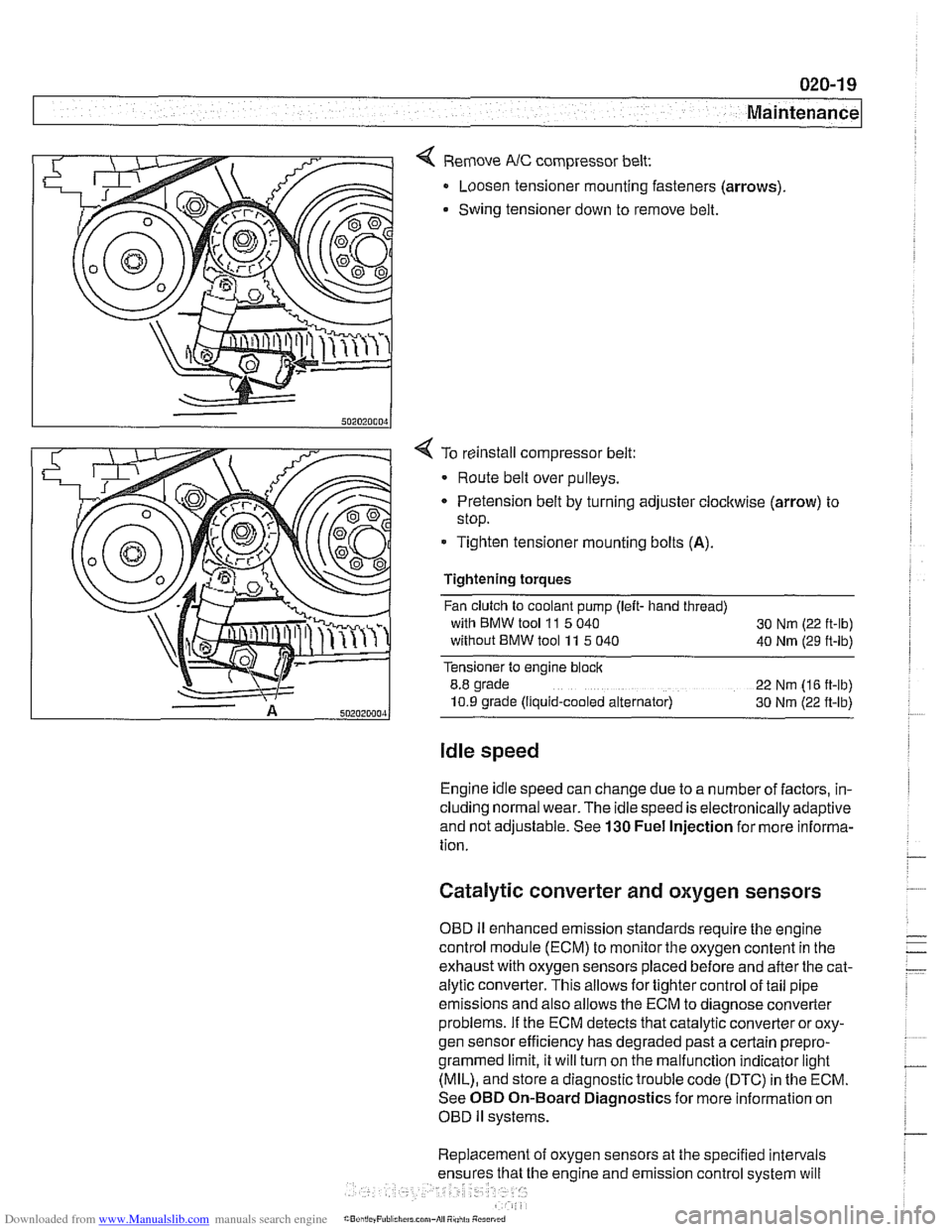
< Remove NC compressor belt:
Loosen tensioner mounting fasteners (arrows)
Swing tensioner down to remove belt.
4 To reinstall compressor belt:
Route belt over pulleys.
* Pretension belt by turning adjuster clockwise (arrow) to
stop.
- Tighten tensioner mounting bolts (A).
Tightening torques
Fan clutch to coolant pump (left- hand thread)
with BMW tool
11 5 040
30 Nm (22 ft-lb)
without BMW tool 11 5 040
40 Nm (29 ft-lb)
Tensioner to engine block
8.8 grade
22 Nm (16 ft-lb)
10.9 grade (Ilquid-cooled alternator) 30 Nm (22 ft-lb)
Idle speed
Engine idle speed can change due to a number of factors, in-
cluding normal wear. The idle speed is electronically adaptive
and not adjustable. See
130 Fuel Injection for more informa-
tion.
Catalytic converter and oxygen sensors
OBD II enhanced emission standards require the engine
control module (ECM) to monitor the oxygen content in the
exhaust with oxygen sensors placed before and after the cat-
alytic converter. This allows for tighter control of tail pipe
emissions and also allows the ECM to diagnose converter
problems. If the ECM detects that catalytic converter or oxy-
gen sensor efficiency has degraded past a certain
prepro-
grammed limit, it will turn on the malfunction indicator light
(MIL), and store a diagnostic trouble code (DTC) in the ECM.
See OBD On-Board Diagnostics for more information on
OBD
ll systems.
Replacement of oxygen sensors at the specified intervals
he engine and emission control system will
Page 83 of 1002

Downloaded from www.Manualslib.com manuals search engine
Engine Removal and installatid
4 Remove cylinder head top cover:
Remove plastic trim caps
(arrows).
Remove cover retaining fasteners and lifl off cover.
- Remove alternator cooling tube.
4 Drain engine coolant and remove coolant hoses:
* Remove expansion tank cap on coolant reservoir.
Place a
3 gallon pail beneath engine to capture coolant,
* Remove coolant drain plug located on exhaust side of
cylinder
2 of engine block (arrow).
NOTE-
Drain plug for M52 TU and M54 engine shown. Plug for M52
located between cylinders 4 and 5.
Drain radiator by removing plastic drain plug (arrow) from
bottom of radiator.
WARNING-
Use extreme caution when draining and disposing of engine
coolant Coolant is poisonous andlethal to humans andpets.
Pets are attracted to coolant because of its sweet smell and
taste. Seek medical attention immediately if coolant is ingest-
ed.
NOTE-
Catch and dispose of drained coolant according to local,
state, and federal laws.
Page 89 of 1002

Downloaded from www.Manualslib.com manuals search engine
- .. -.
-. Engine Removal and in=/
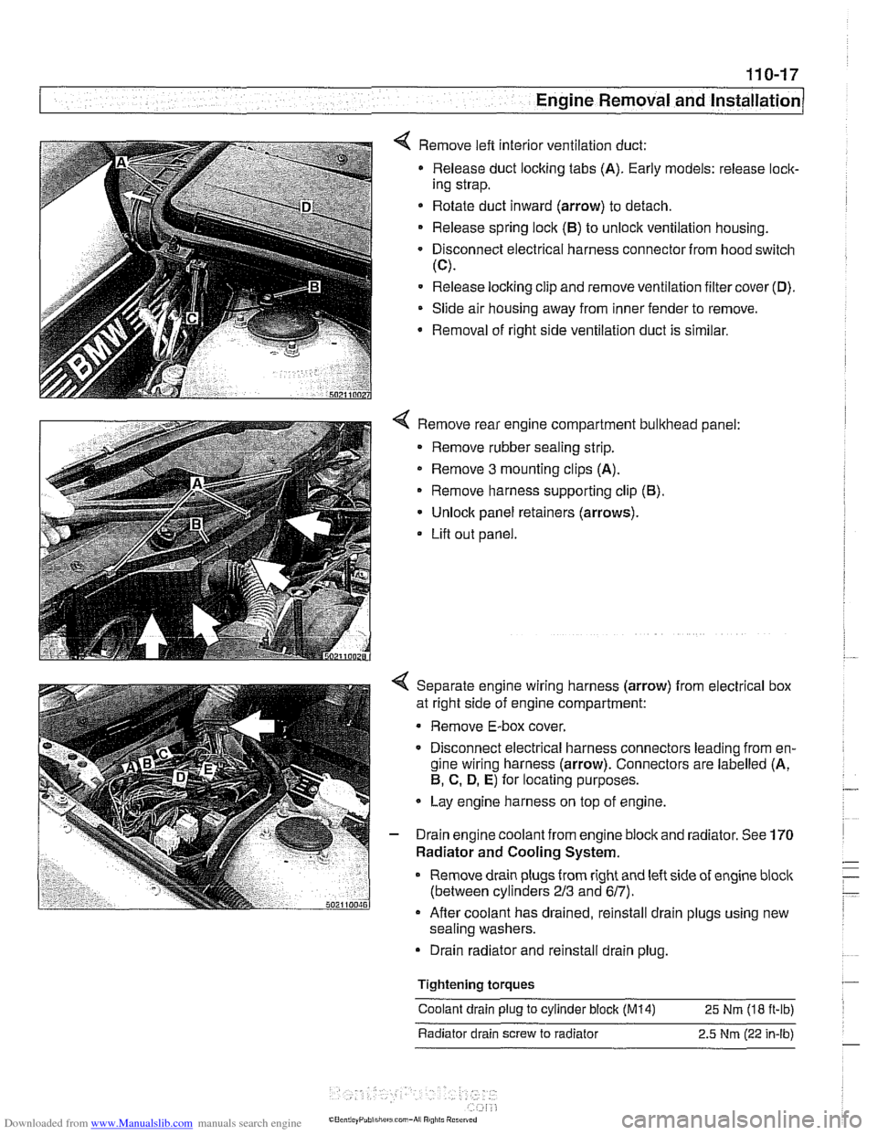
4 Remove left interior ventilation duct:
Release duct locking tabs (A). Early models: release
loclc
ing strap.
* Rotate duct inward (arrow) to detach.
Release spring
loclc (El) to unlock ventilation housing.
Disconnect electrical harness connector from hood switch
(C).
Release locking clip and remove ventilation filter cover (D).
Slide air housing away from inner fender to remove.
Removal
of right side ventilation duct is similar.
4 Remove rear engine compartment bulkhead panel:
Remove rubber sealing strip.
* Remove 3 mounting clips (A).
Remove harness supporting clip
(El).
Unlock panel retainers (arrows).
Lifl out panel.
< Separate engine wiring harness (arrow) from electrical box
at right side of engine compartment:
Remove E-box cover.
Disconnect electrical harness connectors leading from en-
gine wiring harness (arrow). Connectors are labelled (A,
El, C. D, E) for locating purposes.
Lay engine harness on top of engine.
- Drain engine coolant from engine block and radiator. See 170
Radiator and Cooling System.
Remove drain plugs from right and left side of engine
bloclc
(between cylinders 213 and 617).
Afler coolant has drained, reinstall drain plugs using new
sealing washers.
Drain radiator and reinstall drain plug.
Tightening
torques
Coolant drain plug to cylinder block (M14) 25 Nm (18 ft-ib)
Radiator drain screw to radiator 2.5
Nm (22 in-lb)
Page 109 of 1002

Downloaded from www.Manualslib.com manuals search engine
Cylinder Head Removal and Installation / -
< Use a spanner tool to rotate exhaust sprocket until stop on in-
take sprocket is contacted.
- Slide VANOS control unit forward to remove
Remove primary chain tensioner (arrow)
WARNING -
Remove tensioner slowly - it is under spring pressure. I
- Working at the intake side of cylinder 1 :
Detach electrical harness connector for camshaft position
sensor and remove sensor.
Detach electrical harness connector for coolant tempera-
ture sensor.
- Remove exhaust manifolds. D~scard nuts. See 180 Exhaust
System.
Disconnect heating system hoses (arrows) from back of cyl-
inder head.
Page 160 of 1002

Downloaded from www.Manualslib.com manuals search engine
. .- --
I Cylinder Head Removal and Installation
- Evaluate cylinder head as described in 116 Cylinder head
and valvetrain.
Left cylinder head, installing, M62 engine
- Clean cylinder head and block sealing surfaces of gasket
debris, making sure no debris drops into coolant or oil pas-
sages.
- Clean cylinder head bolt holes and check condition of
threads.
< Check cylinder head locator sleeves (arrows) for damage.
If the cylinder head has been machined, a special
0.3 mm
thicker gasket should be installed. The thicker gasket is avail-
able through an authorized
BMW dealer and should be
marked accordingly.
- Place new cylinder head gasket over locating sleeve on
block.
The word
"OBEN" or "TOP" (arrow) printed on the gasket,
must face up.
Set lefl side cylinder head in position on cylinder block while
pressing oil separator outward.
CAUJION-
Male sure the crankshaft, which had been rotated approxi-
mately
45" opposite the direction of engine rotation from
TDC, is still in thatposition before installing the cylinder head.
All pistons must be out of
TDCposition to prevent valvelpis-
ton contact.
- Install new cylinder head bolts and washers finger tight. Be
sure not to remove coating from new cylinder head bolts.
4 Tighten cylinder head bolts in correct sequence (1-10) to
stage
1 torque values.
Page 171 of 1002

Downloaded from www.Manualslib.com manuals search engine
Cvlinder Head Removal and Installation /
Right cylinder head, installing, M62 engine
- Clean cylinder head and block sealing surfaces of gasket de-
bris, making sure no debris drops into coolant or oil passag-
es.
CA UTIOW-
To prevent valve to piston contact when tightening camshaft
sprocket fasteners, counterhold camshaft with
27 mm open-
end wrench. If
necessarq: grind outer side of wrench jaws to
prevent damaging cylinder head.
- Check cylinder head bolt holes and condition of threads. Re-
move debris and liquids from holes.
4 Check cylinder head locator sleeves (arrows) for damage
CAUTION-
lithe cylinder head has been machined, a special 0.3 rnm
(0.01 1 in.) thickergasket should be installed. The thickergas-
ket is available through an authorized BMW dealer and
should be marked
accordinglw
- Place new cylinder head gasket over locating sleeve on
block.
< The word "OBEN" or "TOP (arrow) printed on the gasket.
must face up.
CAUTION-
Male sure the crankshaft, which had been rotated approxi-
mately
45" opposite the direction of engine rotation from
TDC, is
stillin thatposition before installing the cylinder head.
All pistons must be out of
TDCposition to prevent valve/pis-
ton contact
- Install new cylinder head bolts and washers finger tight. Be
sure not to remove coating from bolts.
4 Tighten cylinder head bolts in correct sequence (1 -10) to
stage
1 torque values.