Page 432 of 759

612-4
SWITCHES
AND
ELECTRICAL
ACCESSORIES
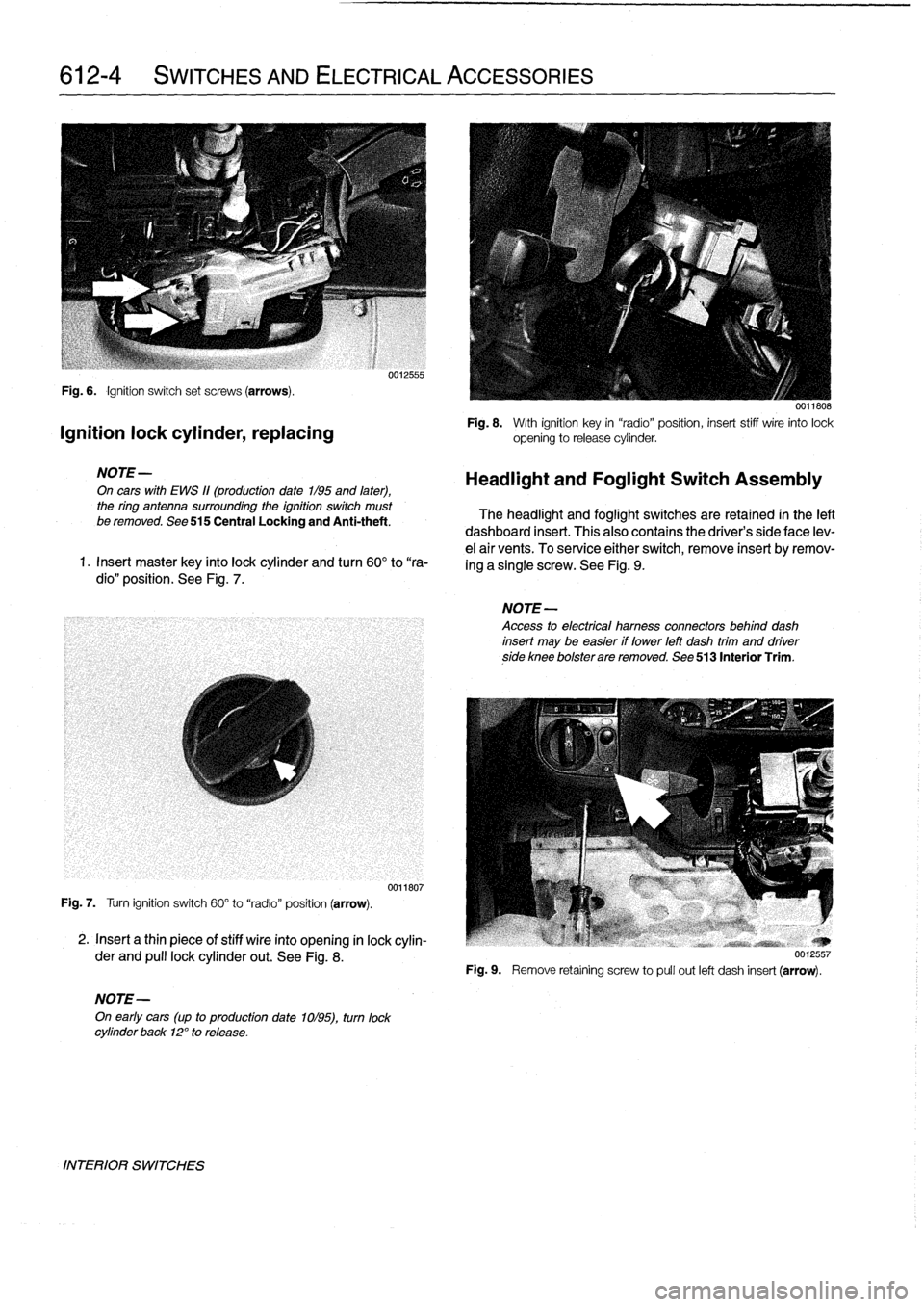
Fig
.
6
.
Ignition
switch
set
screws
(arrows)
.
Ignition
lock
cylinder,
replacing
NOTE-
On
cars
with
EWS
11(production
date
1/95
and
later),
the
ring
antenna
surrounding
the
ignition
switch
must
be
removed
.
See
515
Central
Locking
and
Anti-theft
.
1
.
Insert
master
key
finto
lock
cylinder
and
turn
60°
to
"ra-
dio"
position
.
See
Fig
.
7
.
Fig
.
7
.
Turn
ignition
switch
60°
to
"radio"
position
(arrow)
.
2
.
Insert
a
thin
piece
of
stiff
wire
into
opening
in
lock
cylin-
der
and
pull
lockcylinder
out
.
See
Fig
.
8
.
NOTE-
On
early
cars
(up
to
production
date
1ol95),
turn
lock
cylinder
back
12°
to
release
.
INTERIOR
SWITCHES
0012555
0011807
0011808
Fig
.
8
.
With
ignition
key
in
"radio"position,
insert
stiff
wire
into
lock
opening
to
release
cylinder
.
Headlight
and
Foglight
Switch
Assembly
The
headlight
and
foglight
switches
are
retained
in
the
left
dashboard
insert
.
This
alsocontains
the
driver's
side
face
lev-
e¡
air
vents
.
To
service
either
switch,
remove
insert
byremov-
ing
a
single
screw
.
See
Fig
.
9
.
NOTE-
Access
to
electrical
hamess
connectors
behind
dash
insert
may
be
easier
if
lower
left
dash
trim
and
driverside
knee
bolsterare
removed
.
See
513
Interior
Trim
.
Fig
.
9
.
Remove
retaíning
screw
to
pull
out
left
dash
insert
(arrow)
.
Page 440 of 759

620-
4
INSTRUMENTS
MULTI-INFORMATION
DISPLAY
(MID)
Severa¡
different
versionsof
the
Multi-Information
Display,
have
been
installed
in
E36
cars
.
The
top-of-the-line
model
is
called
the
Oh-BoardComputer
.
See
Fig
.
8
.
Ambient
temperature/ciock
Check
control/clock
0013028
Fig
.
8
.
Different
versions
of
Multi-Information
Display
(MID)
installed
in
E36
cars
.
Multi-Information
Display,
removing
and
installing
The
Multi-Information
Display
(MID)
is
illuminated
by
bulbs
.
It
mustbe
removed
to
replace
the
bulbs
.
Bulb
replacement
is
included
in
this
procedure
.
1
.
Remove
dashboard
parcel
shelf
.
Reach
under
MID
module
and
pushoutward
.
See
Fig
.
9
.
2
.
Slide
harness
retaining
lever
forward
to
release
MID
from
wiring
harness
.
See
Fig
.
10
.
3
.
To
Rmove
a
faulty
bulb,
use
anarrow
screwdriver
to
turn
bulb
base
45°
counter
clockwíse
.
See
Fig
.
11
.
MULTI-INFORMATIONDISPLAY
(MID)
111
Fig
.
9
.
Removing
the
Multi-Information
Display(MID)
module
.
0012564
Fig
.
10
.
MID
wiring
harness
release
lever
(arrows)
.
Fig
.
11
.
Turn
bulb
base
45°
counterclockwise
.
4
.
Installation
is
reverse
of
removal
.
0012566
Page 450 of 759

640-4
HEATING
AND
AIR
CONDITIONING
Heater
box,
removing
and
installing
The
heater
box,
located
underneath
thecenter
of
the
dash-
board,
houses
theheater
core,
the
A/C
evaporator,
and
asso-
ciated
sensors
and
actuators
.
Removal
of
theheater
box
requires
that
the
A/C
refrigerant
be
discharged
.
CAUTION-
"
Removing
the
heater
box
requires
evacuating
the
AIC
system
.
DO
NOT
attempt
this
procedure
without
proper
tools
and
training
.
"
Any
person
who
services
a
motor
vehicle
air
con-
ditioner
must,
by
law,
be
properly
trained
and
cer-
tified,
and
use
approved
refrigerant
recycling
equipment
.
Technicians
must
complete
an
EPA-
approved
recycling
course
to
be
certified
UU12639
Fig
.
10
.
Heater
core
mounting
nuts
at
left
sideof
bulkhead
(arrow)
.
1
.
Drain
engine
coolant
.
See
170
Radiator
and
Cooling
wiper
assembly
shown
removed
for
clarity
.
System
.
2
.
Remove
complete
dashboard
.
See513
Interior
Trim
.
3
.
Remove
blower
motoras
described
earlier
.
4
.
Remove
nut
retaining
water
hose
flange
to
rear
bulk-
head
.
I'ush
flange
to
one
side
.
See
Fig
.
9
.
Fig
.
9
.
Nut
retaining
coolant
hose
flangeat
bulkhead
(arrow)
.
NOTE-
Clear
any
remaining
coolant
from
the
heater
core
by
blowing
compressed
air
finto
the
coolant
feed
hose
.
HEATER
AND
CONTROLS
0012638b
6
.
Cut
wire
tie
holding
wire
harness
to
heater
box
and
dis-
connect
cable
harness
connector
from
heater
box
.
See
Fig
.
11
.
0012647
Fig
.
11
.
Harness
connectors
(A)
and
cable
tie
(B)
at
heaterbox,
under
driver
side
dash
.
7
.
Followingmanufacturer's
instructions,
connect
ap-
proved
refrigerant
recovery/recycling/recharging
unitto
A/C
system
and
discharge
system
.
8
.
Unbolt
A/C
refrigerantlines
flange
from
engine
bay
bulkhead
.
See
Fig
.
12
.
9
.
On
models
with
rotary-knob
A/C
control
head
:
Discon-
5
.
Remove
nuts
from
heater
box
retaining
bracket
on
en-
nect
wiring
harness
connectors
to
A/C
control
module
gine
bulkhead
left
side
.
See
Fig
.
10
.
Repeat
procedure
in
center
console
and
remove
module
.
See
Fig
.
13
.
for
right
side
nuts
.