1997 BMW 328i engine mount
[x] Cancel search: engine mountPage 427 of 759

WINDSHIELD
CLEANING
SYSTEM
Washer
f
luid
reservoir,
replacing
1
.
Open
hood
and
siphon
out
washer
fluid
reservoir
.
The
windshieldcleaning
system
includes
the
spray
nozzles
in
the
engine
hood,
the
washer
fluid
pump,
and
the
washer
flu-
id
reservoir
in
the
front
passenger
side
of
the
engine
compart-
ment
.
The
windshield
spray
nozzles
can
be
aimed
by
using
asew-
ing
need1e
or
a
similar
diameter
stiff
piece
of
wire
.
Windshield
spray
nozzle,
removing
and
installing
1
.
Open
hood
andremove
hood
insulating
pad
retaining
clips
until
bottom
of
nozzle
canbe
fully
accessed
.
See
410
Fenders,
Engine
Hood
.
2
.
Carefully
disconnect
hose
from
nozzle
.
Disconnect
har-
ness
connectors
for
nozzleheater
.
3
.
Push
nozzleout
of
hood
.
See
Fig
.
21
.
Fig
.
21
.
First
push
nozzle
forward
then
upward
from
underneath
hood
.
4
.
Installation
is
reverse
of
removal,
noting
the
following
:
"
Check
that
colors
of
harness
and
nozzle
connector
match
.
"
Check
and
adjust
nozzles
before
driving
.
WIPERSAND
WASHERS
611-
9
2
.
Remove
windshield
washer
pump
and
hose
as
de-
scribed
later
.
3
.
Remove
windshield
washer
fluid
level
sensor
as
de-
scribed
later
.
4
.
Remove
large
plastic
washer
reservoir
retainer
at
fend-
e
r
.
5
.
Remove
reservoir
.
6
.
Installation
is
reverse
of
removal,
noting
the
following
:
"
On
installation
check
that
washer
fluid
hose
is
not
kinked
.
"
Replacehose
clamp
.
Windshield
washer
fluid
pump,
replacing
The
windshield
washer
fluid
pump
ís
mounted
in
the
washer
fluid
reservoir
.
1
.
Open
hood
and
siphon
out
washer
fluid
reservoir
.
2
.
Depress
retaining
tabs
on
electrical
connector
and
un-
plug
harness
connector
from
pump
.
3
.
Loosen
hose
clamp
and
remove
washer
fluidline
from
washer
pump
.
4
.
PA
pump
out
of
tank
.
See
Fig
.
22
.
Fig
.
22
.
Pull
windshield
washer
pump
up
to
remove
(arrow)
.
5
.
Installation
is
reverse
of
removal
.
Check
pump
to
tank
sealing
grommet
for
damage
and
correct
fit
.
Replace
hose
clamp
.
Check
that
washer
fluid
hose
is
free
of
kinks
.
WINDSHIELD
CLEANING
SYSTEM
Page 438 of 759

620-2
INSTRUMENTS
Fig
.1.
Instrument
cluster
retaining
screws
(arrows)
.
INSTRUMENT
CLUSTER
0012562
Fig
.
3
.
Turnbulb
base
45°
in
direction
shown
(arrow)
.
l
v
w
r
v
9
10
11
12
13
14
15
16
)7
18
19
20
y
21
1
.
Temperature
warning
12
.
Brake
fluid
warning
oo13n6
2
.
Right
turn
signal
13
.
Brake
pad
wear
warning
3
.
Instrument
lighting
14
.ABS
warning
Fig
.
2
.
Instrument
cluster
connector
locking
lever
(arrow)
.
4
.
Oil
pressure
warning
15
.
Seat
belt
warning5
.
Highbeam
16
.ASTwarning
6
.
Battery
charging
lamp
17
.Check
control
6
.
Installation
is
reverse
of
removal,
noting
the
following
:
7
.
Left
turn
signal
18
.Check
engine
"
Instrument
cluster
harness
connector
locking
levers
8
.
Low
fuel
warning
19
.
LCD
lighting
must
be
in
up
position
before
installing
connector
.
9
.
Airbag
warning
20
.
Rear
foglight
(not
used)
10
.
Catalytic
converter
warning
21
.
Front
foglights
"
Install
airbag
to
steering
wheel
as
described
in
721
11
.
Emergency
brake
Airbag
System
(SRS)
.
0012563
"
Reconnect
negative
(-)
cable
to
battery
last,
once
al¡
Fig
.
4
.
Bulb
designation
chart
.
harness
connectors
have
been
reconnected
.
"
Recode
cluster
as
described
in
Instrument
cluster,
CAUTION-
seif-testing
.
Note
wattage
of
bulb
.
Excessive
wattage
could
melt
cluster
housing
.
Replace
defective
bulbs
with
Instrument
cluster
bulbs,
replacing
reptacementbulbs
of
the
same
wattage
.
1
.
Remove
instrument
cluster
as
described
above
.
Odometer
coding
plug,
replacing
2
.
Remove
faulty
bulb
by
turning
bulb
base
45°
inits
mount
and
remove
from
housing
.
See
Fig
.
3
.
The
coding
plug
maintains
a
record
of
thevehicle
mileage
.
The
back
of
the
instrument
cluster
and
its
bulb
locations
are
1
.
Record
vehicle
mileage
.
shown
in
Fig
.
4
.
2
.
Remove
instrument
cluster
as
described
earlier
.
Page 442 of 759

630-2
EXTERIOR
LIGHTING
Headlight
assembly,
removing
and
installing
CAUTION-
Followingheadlight
assembly
work
headlight
beam
aim
must
be
adjusted
using
special
equip-
ment
.
1
.
Left
side
:
Remove
air
filter
housing,
air
intake
duct,
and
air
mass
meter
.
See
100
Engine-General
.
2
.
Disconnect
harness
connectors
from
headlight
bulbs
.
3
.
Remove
front
turn
signal
.
See
Front
turn
signal
as-
sembly,
removingand
installing
later
in
this
repair
group
.
4
.
Remove
radiator
cover
.
See
Fig
.
2
.
5
.
Using
a
wrench,
brace
adjusting
nut
at
top
center
of
headlight
.
Remove
three
screws
at
top
of
assembly
.
See
Fig
.
3
.
Fig
.
3
.
Brace
headlightadjustingnut
as
shown
and
remove
top
screws
(arrows)
.
FRONT
LIGHTING
0012568
0012569
6
.
Remove
two
screwson
bottom
of
assembly
.
See
Fig
.
4
.
0012567a
Fig
.
4
.
Headlight
bottom
retaining
screws
(arrows)
.
Screws
mount
in
threaded
expanding
rivets
which
act
as
headlightheight
adjusters
.
7
.
Remove
headlight
assembly
from
front
.
8
.
On
installation,
tighten
lower
screws
first
while
holding
expanding
rivets
with
a
wrench
.
There
should
be
a
2
.5
mm
gap
between
bottom
oflens
and
front
panel
.
Use
adjusting
nut
to
raise
or
lower
headlight
unit
.
See
Fig
.
5
.
0012681
Fig
.
5
.
Measure
gap
A
(2.5
mm)
between
bottom
of
headlight
as-
sembly
and
front
panel
.
9
.
Clearance
between
hood
and
headlight
cover
should
be
1
.5
mm
.
Adjust
by
turning
upper
headlight
adjustinq
nuts,
then
tighten
down
center
screw
.
See
Fig
.
6
.
Page 449 of 759

9
.
Release
blower
motor
retaining
strap
andremove
blow-
er
motor
and
fans
fromcowl
opening
.
NOTE-
Twist
and
rotate
blowermotor
assembly
to
facilítate
re-
moval
from
opening
.
If
the
blower
motor
is
to
be
rein-stafled,
use
care
not
to
damage
fan
wheels
during
removal
.
ff
the
blower
motor
fs
to
be
replaced,
cut
offfan
wheels
at
center
to
aid
in
removal
.
10
.
Installation
is
reverse
of
removal
.
When
installing
a
re-
placement
blower
motor,
instan
motor
into
cowlarea
before
installing
fan
wheels
.
Blower
motor
test
specifi-
cations
are
listed
in
Table
a
.
NOTE
-
On
replacementblowermotors
from
BMW,
thefan
wheels
come
unattached
to
aid
in
installation
.
Locatearrow
on
blower
motor
and
instan
fan
wheels
atthis
po-
sition
.
Be
sure
color
coolng
matches
.
Retain
fan
wheels
using
the
new
clips
.
See
an
authorized
BMW
parts
de-
partment
for
the
latest
parts
information
.
Table
a
.
Blower
Motor
Test
Values
Testingvoltage
13
VDC
Operating
voltage
9-15
VDC
Max
.
current
consumption
(approx
.)
12
amps
Maximum
speed
3,600-4,000rpm
Axialplay
(max
.
allowable)
1
.0
mm
(0
.04
in
.)
Blower
motor
resistor
pack,
replacing
The
blower
resistor
pack
is
clipped
into
the
upper
left
side
of
theheater
box
.
1
.
Remove
lower
left
dash
trim
panel
.
See513
Interior
Trim
.
2
.
Working
under
left
(driver's)
side
of
dash,
unclip
and
pulí
out
resistor
pack
from
sideof
heater
box
.
Remove
harness
connector
from
resistor
pack
.
See
Fig
.
7
.
3
.
Installation
is
reverse
of
removal
.
Heater
valve,
replacing
The
two-way
heater
valve
is
located
in
the
rear
of
the
engine
compartment
on
the
driver
side
.
The
solenoid
operated
valves
control
the
coolant
flow
through
the
dual-chamber
heater
core
.
1
.
Drain
engine
coolant
.
See
170
Radiator
and
Cooling
System
.
HEATING
AND
AIR
CONDITIONING
640-
3
uuiGO4I
Fig
.
7
.
Blower
fan
resistor
pack
(black
arrow)
and
resistor
pack
re-
ceptacle
(white
arrow)
below
left
sideof
dash
.
WARNING
-
Allow
the
cooling
system
to
cool
before
opening
ordraining
the
cooling
system
.
2
.
Disconnect
hoses
and
harness
connector
at
heater
valve
.
See
Fig
.
8
.
001[ó38b
Fig
.
S
.
Hoses
(A)
and
harnessconnector
(B)
at
heatervalve
.
3
.
Carefully
pull
heater
valve
out
of
rubber
mounting
and
pull
up
and
out
of
engine
compartment
.
4
.
Installation
is
reverse
of
removal
.
Use
new
hose
clamps
.
Inspect
hoses
and
replace
asnecessary
.
HEATER
AND
CONTROLS
Page 450 of 759

640-4
HEATING
AND
AIR
CONDITIONING
Heater
box,
removing
and
installing
The
heater
box,
located
underneath
thecenter
of
the
dash-
board,
houses
theheater
core,
the
A/C
evaporator,
and
asso-
ciated
sensors
and
actuators
.
Removal
of
theheater
box
requires
that
the
A/C
refrigerant
be
discharged
.
CAUTION-
"
Removing
the
heater
box
requires
evacuating
the
AIC
system
.
DO
NOT
attempt
this
procedure
without
proper
tools
and
training
.
"
Any
person
who
services
a
motor
vehicle
air
con-
ditioner
must,
by
law,
be
properly
trained
and
cer-
tified,
and
use
approved
refrigerant
recycling
equipment
.
Technicians
must
complete
an
EPA-
approved
recycling
course
to
be
certified
UU12639
Fig
.
10
.
Heater
core
mounting
nuts
at
left
sideof
bulkhead
(arrow)
.
1
.
Drain
engine
coolant
.
See
170
Radiator
and
Cooling
wiper
assembly
shown
removed
for
clarity
.
System
.
2
.
Remove
complete
dashboard
.
See513
Interior
Trim
.
3
.
Remove
blower
motoras
described
earlier
.
4
.
Remove
nut
retaining
water
hose
flange
to
rear
bulk-
head
.
I'ush
flange
to
one
side
.
See
Fig
.
9
.
Fig
.
9
.
Nut
retaining
coolant
hose
flangeat
bulkhead
(arrow)
.
NOTE-
Clear
any
remaining
coolant
from
the
heater
core
by
blowing
compressed
air
finto
the
coolant
feed
hose
.
HEATER
AND
CONTROLS
0012638b
6
.
Cut
wire
tie
holding
wire
harness
to
heater
box
and
dis-
connect
cable
harness
connector
from
heater
box
.
See
Fig
.
11
.
0012647
Fig
.
11
.
Harness
connectors
(A)
and
cable
tie
(B)
at
heaterbox,
under
driver
side
dash
.
7
.
Followingmanufacturer's
instructions,
connect
ap-
proved
refrigerant
recovery/recycling/recharging
unitto
A/C
system
and
discharge
system
.
8
.
Unbolt
A/C
refrigerantlines
flange
from
engine
bay
bulkhead
.
See
Fig
.
12
.
9
.
On
models
with
rotary-knob
A/C
control
head
:
Discon-
5
.
Remove
nuts
from
heater
box
retaining
bracket
on
en-
nect
wiring
harness
connectors
to
A/C
control
module
gine
bulkhead
left
side
.
See
Fig
.
10
.
Repeat
procedure
in
center
console
and
remove
module
.
See
Fig
.
13
.
for
right
side
nuts
.
Page 456 of 759

640-10
HEATING
AND
AIR
CONDITIONING
i
El
Radio
Antenna
Rear
.
,
si,-
Left
side
I
d
1
.
Rear
vents
2
.
Fresh
air
3
.
Face-level
vents
4
.
Recirculation
5
.
Footwell
vents
0013017
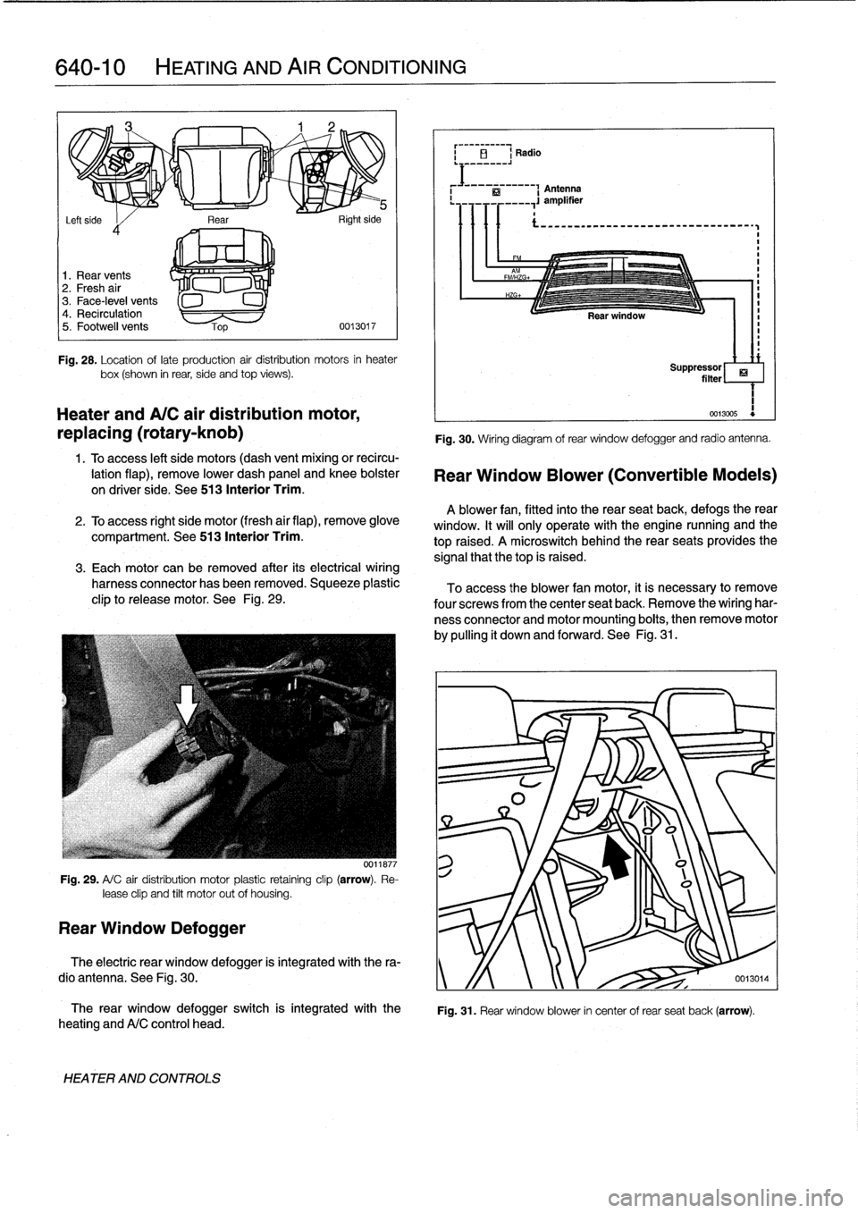
Fig
.
28
.
Location
oflate
production
air
distribution
motors
in
heater
box(shown
in
rear,
side
and
top
views)
.
Heater
andA/C
air
distribution
motor,
replacing
(rotary-knob)
1
.
Toaccess
left
side
motors
(dash
vent
mixing
or
recircu-
lation
flap),
remove
lower
dash
panel
and
knee
bolster
on
driver
side
.
See
513
Interior
Trim
.
2
.
To
access
right
side
motor
(fresh
air
flap),
remove
glove
compartment
.
See513
Interior
Trim
.
3
.
Each
motor
can
be
removed
after
its
electrical
wiring
harness
connector
has
been
removed
.
Squeeze
plastic
clip
to
release
motor
.
See
Fig
.
29
.
Fig
.
29
.
A/
C
air
distribution
motor
plastic
retaíning
clip
(arrow)
.
Re-
lease
clip
and
tilt
motor
out
of
housing
.
Rear
Window
Defogger
0011877
The
rear
window
defogger
switch
is
integrated
with
the
heating
andA/C
control
head
.
HEATER
AND
CONTROLS
Fig
.
30
.
Wiring
diagram
of
rear
window
defogger
and
radio
antenna
.
Rear
Window
Blower
(Convertible
Models)
A
blower
fan,
fitted
into
the
rear
seatback,
defogs
therear
window
.
It
will
only
operate
with
the
engine
nunning
and
the
top
raised
.
A
microswitch
behindthe
rear
seats
provides
the
signal
that
thetop
is
raised
.
To
access
the
blower
fan
motor,
it
is
necessary
to
remove
four
screwsfrom
the
center
seat
back
.
Remove
the
wiring
har-
ness
connector
and
motor
mounting
boits,
then
remove
motor
by
pulling
it
down
and
forward
.
See
Fig
.
31
.
ri
Suppressor
filter
1
0013005
Fig
.
31
.
Rear
window
blower
in
center
of
rear
seat
back
(arrow)
.
The
electric
rear
window
defogger
is
integrated
with
the
ra-
dio
antenna
.
See
Fig
.
30
.
y
/f
0013014
Page 459 of 759

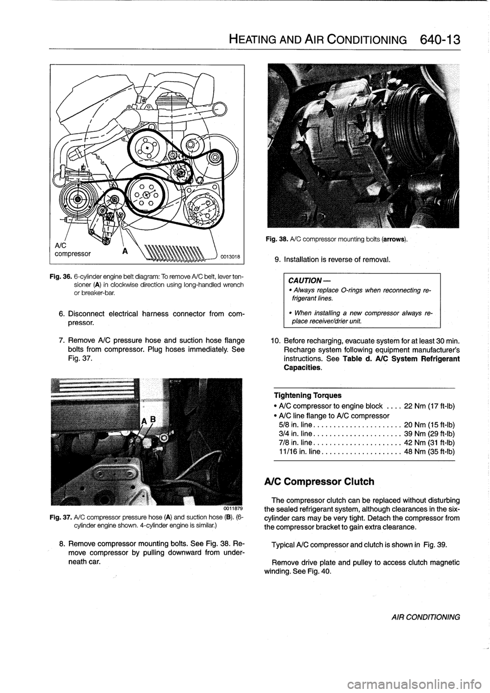
Fig
.
36
.
6-cylinder
engine
belt
diagram
:
To
remove
A/C
belt,
lever
ten-
sioner
(A)
in
clockwise
direction
using
long-handled
wrench
or
breaker-bar
.
6
.
Disconnect
electrical
harness
connector
from
com-
pressor
.
7
.
Remove
A/C
pressure
hose
and
suction
hose
flange
10
.
Before
recharging,
evacuate
system
for
at
least
30
min
.
bolts
from
compressor
.
Plug
hoses
immediately
See
Recharge
system
following
equipment
manufacturer's
Fig
.
37
.
instructions
.
See
Table
d
.
A/C
System
Refrigerant
Capacities
.
0011879
Fig
.
37
.
A/
C
compressor
pressure
hose
(A)
and
suction
hose
(B)
.
(6-
cylinder
engine
shown
.
4-cylinder
engine
is
similar
.)
HEATING
AND
AIR
CONDITIONING
640-
1
3
Fig
.
38
.
A/
C
compressor
mounting
boits
(arrows)
.
9
.
Installation
is
reverseof
removal
.
CAUTION
-
"
Always
replaceO-rings
when
reconnecting
re-
frigerantfines
.
"
When
installlng
a
new
compressor
always
re-
place
receiverldrier
unit
.
Tightening
Torques
"
A/C
compressor
to
engine
block
....
22
Nm
(17
ft-Ib)
"
A/C
line
flange
to
A/C
compressor
5/8
in
.
fine
.
......
.....
....
.
.....
20
Nm
(15
ft-Ib)
3/4
in
.
fine
.......
.....
..........
39
Nm
(29
ft-Ib)
7/8
in
.
fine
...
....
.....
..........
42
Nm
(31
ft-Ib)
11/16
in
.
fine
.....
..
..
..
...
.
.....
48
Nm
(35
ft-Ib)
A/C
Compressor
Clutch
The
compressor
clutch
can
be
replaced
without
disturbing
thesealed
refrigerant
system,
although
clearances
in
the
six-
cylinder
cars
may
be
very
tight
.
Detach
the
compressor
from
the
compressor
bracket
togain
extra
clearance
.
8
.
Remove
compressor
mounting
boits
.
See
Fig
.
38
.
Re-
Typical
A/C
compressor
and
clutch
is
shown
in
Fig
.
39
.
move
compressor
by
pulling
downward
from
under-
neath
car
.
Remove
driveplate
and
pulley
to
access
clutch
magnetic
winding
.
See
Fig
.
40
.
AIR
CONDITIONING
Page 461 of 759

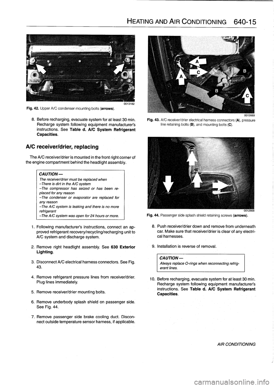
Fig
.
42
.
Upper
A/C
condensermounting
bolts
(arrows)
.
8
.
Before
recharging,
evacuate
system
for
at
least
30
min
.
Recharge
system
following
equipment
manufacturer's
instructions
.
See
Table
d
.
A/C
System
Refrigerant
Capacities
.
A/C
receiver/drier,
replacing
The
A/C
receiver/drier
is
mounted
in
the
front
right
cornee
of
the
engine
compartment
behind
the
headlight
assembly
.
CAUTION-
The
receiver/drier
must
be
replaced
when
-There
is
dirt
in
the
AIC
system
-The
compressor
has
seized
or
has
been
re-
placed
for
any
reason
-The
condenser
or
evaporator
are
replaced
for
any
reason
-The
AIC
system
is
leaking
and
there
is
no
more
refrigerant
-The
AIC
system
was
open
for
24
hours
or
more
.
1
.
Following
manufacturer's
instructions,
connectan
ap-
proved
refrigerant
recovery/recycling/recharging
unit
to
A/C
system
and
discharge
system
.
2
.
Remove
right
headlight
assembly
.
See
630
Exterior
Lighting
.
CAUTION-
3
.
Disconnect
A/C
electrical
harness
connectors
.
See
Fig
.
Always
replaceO-rings
when
reconnecting
refrig-
43
.
erant
lines
.
4
.
Remove
refrigerant
pressure
lines
from
receiver/drier
.
Plug
lines
immediately
.
5
.
Remove
receiver/drier
mounting
bolts
.
0013182
6
.
Remove
underbody
splash
shield
on
passenger
side
.
See
Fig
.
44
.
7
.
Remove
passenger
side
brake
cooling
duct
.
Discon-
nect
outside
temperature
sensor
harness,
if
applicable
.
HEATING
AND
AIR
CONDITIONING
640-15
0012669
Fig
.
43
.
A/
C
receiver/drier
electrical
harness
connectors
(A),
pressure
line
retaining
bolts
(B),
andmounting
bolts
(C)
.
0012668
Fig
.
44
.
Passenger
sidesplash
shield
retaining
screws
(arrows)
.
8
.
Push
receiver/drier
down
andremove
from
underneath
car
.
Make
sure
that
receiver/drier
is
clear
of
any
electri-
cal
harnesses
.
9
.
Installation
is
reverse
of
removal
.
10
.
Before
recharging,
evacuate
system
for
at
least
30
min
.
Recharge
system
following
equipment
manufacturer's
instructions
.
See
Table
d
.
A/C
System
Refrigerant
Capacities
.
AIR
CONDITIONING