1997 BMW 318i switch
[x] Cancel search: switchPage 205 of 759

Fig
.
19
.
Coolant
pump
being
removed
.
Thread
two
M6
bolts
(arrows)
in
evenly
to
withdraw
pump
.
(Thermostat
and
hoseshavebeen
removed
tor
visual
access
.)
8
.
Installation
is
reverse
of
removal
.
"
Be
sure
to
replace
O-ring
and
gaskets
.
"
Coat
O-ring
with
lubricant
during
installation
.
Tightening
Torque
"
Coolant
pump
to
timing
chaincover
M6
...
.
...................
..
.
.
10
Nm
(89
in-lb)
M8
.
..
.
....................
.
.
.
22
Nm
(17
ft-Ib)
"
Coolant
pump
pulley
to
coolant
pump
.................
10
Nm
(89
in-lb)
RADIATOR
SERVICE
Radiator,
removing
and
installing
1
.
Drain
radiator
as
described
earlier
.
WARNING
-
Allow
cooling
system
to
cool
before
opening
ordraining
system
.
2
.
Remove
primary
cooling
fan
(belt-driven
or
electric)
as
described
earlier
.
3
.
Disconnect
coolingfan
and
leve¡
sensor
harness
con-
nectors
from
bottom
of
radiator,
where
applicable
4
.
Disconnect
harness
connector
from
auxiliary
fandual
temperature
switch
.
See
Fig
.
20
.
5
.
Disconnect
all
coolant
hoses
from
radiator
.
RADIATOR
AND
COOLING
SYSTEM
170-11
0012500
Fig
.
20
.
Cooling
fan
dual
temperatura
switch
(arrow)
on
right
sido
of
radiator
.
6
.
Where
applicable,
disconnectautomatic
transmission
fluid
(ATF)
cooler
lines
from
radiator
.
See
Fig
.
21
.
Fig
.
21
.
Automatic
transmission
fluid
(ATF)
linos
at
radiator
.
7
.
Carefully
pryout
radiator
retaining
clips
from
top
of
ra-
diator
.
See
Fig
.
22
.
8
.
Pul¡
radiator
up
and
out
of
car
.
NOTE-
The
radiator
rests
ontwo
rubber
mounts
.
Check
that
the
mounts
do
not
stick
to
the
bottomof
the
radiator
.
RADIATOR
SERVICE
Page 221 of 759

230
Manual
Transmission
MANUAL
TRANSMISSION
230-1
GENERAL
...
.
............
.
.......
.
.
.
.
230-1
Output
shaft
sea¡,
replacing
(transmission
installed)
....
.
.....
.
.....
.230-4
TRANSMISSION
FLUID
SERVICE
.
.
.
.
.
.
.230-1
Inputshaft
sea¡,
replacing
Transmission
fluid
leve¡,
checking
...
.
...
.
.
230-2
(transmission
removed)
.
.
.
.
...
.
.
.
.....
.
230-5
Transmission
fluid,
replacing
.........
.
.
.
.
230-2
TRANSMISSION
REMOVAL
AND
TRANSMISSION
SERVICE
.
.
.....
.
.
.
.
.
.
230-2
INSTALLATION
.
.
.
.
.
.
.....
.
.
.
.
.
.
.
.....
.
230-5
Back-up
light
switch,
replacing
.
.
.
...
.
.
.
.
.
.
230-2
Transmission,
removing
and
installing
...
.
.
.
.
230-6
_
Selector
shaft
sea¡,
replacing
(transmission
installed)
.
.
.
.
.
.
.
.
.
.
.
...
.
.
230-3
TAB
a
.
Manual
Transmission
Gear
Ratios
.
.
.
.........
.230-1
GENERAL
TRANSMISSION
FLUID
SERVICE
This
repair
group
covers
external
transmission
service,
in-
The
manual
transmissions
installed
in
the
E36
models
are
cluding
removal
and
installation
of
thetransmission
unit
.
Inter-
normally
filled
with
automatic
transmission
fluid
(ATF),
al-
nal
transmission
repair
is
not
covered
.
Special
press
tools
and
though
alternative
lubricants
may
have
beenused
from
the
procedures
are
required
to
disassemble
and
service
the
inter-
factory,
depending
on
transmission
type
and
model
year
.
For
nal
geartrain
.
example,
transmissions
fitted
to
the
M3
models
are
normally
filled
with
a
"lifetime"
manual
transmission
fluid
(BMW
MTF
Manual
transmissions
used
are
based
on
engine
applica-
LT-1)
and
do
not
require
periodic
fluid
changes
.
tion
.
Consult
200
Transmission-General
for
transmission
application
information
.
Table
a
lists
gear
ratio
specifications
.
NOTE-
The
transmission
lubricant
type
can
be
found
ona
label
NOTE-
on
the
sideof
the
transmission
.
Consult
an
authorized
Do
not
rely
on
forged
casting
numbers
for
transmission
BMW
dealer
for
altemate
fluid
use
and
the
most-up-to-
code
identification
.
date
information
regarding
transmission
operating
fluids
.
Tablea
.
Manual
Transmission
Gear
Ratios
Transmission
1
Getrag
S5D
200
G
1
Getrag
SSD
250
G
1
ZF
S5D
310
Z
1
ZF
S5D
320
Z
Gear
Ratios
:
1st
4
.23
4
.23
4
.20
4
.20
2nd
2
.52
2
.52
2
.49
2
.49
3rd
1
.66
1
.66
1
.66
1
.664th
1
.22
1
.22
1
.24
1
.24
5th
1
.00
1
.00
1
.00
1
.00
reverse
4
.04
4
.04
3
.89
3
.89
TRANSMISSION
FLUID
SERVICE
Page 222 of 759

230-2
MANUAL
TRANSMISSION
Transmission
fluidleve¡,
checking
Checking
thetransmission
oil
level
involves
simply
remov-
ing
the
side
drain
plug
and
inserting
a
finger
into
the
holeto
check
the
fluid
leve¡
.
lf
the
fluid
leve¡
is
up
to
the
bottom
of
the
drain
hole
(finger
is
wetted
by
transmission
fluid),
the
leve¡
is
correct
.
Transmission
fluid,
replacing
NOTE-
Manual
transmission
fluid
type
should
be
printed
ona
label
on
the
side
of
the
transmission
.
If
in
doubt,
consult
an
authorized
BMW
dealer
for
the
up-to-dateinforma-
tion
on
operating
fluids
.
1
.
Drive
vehicle
for
afew
miles
to
warm
transmission
.
2
.
Raise
and
safely
support
vehicle
to
access
drain
plug
.
WARNING
-
"
When
raising
the
car
uslng
a
floor
jack
or
a
hy-
draulic
lift,
carefully
position
the
jack
pad
to
pre-
vent
damaging
the
car
body
.
A
suitable
liner
(wood,
rubber,
etc
.)
should
be
placed
between
the
jack
and
the
car
to
prevent
body
damage
.
"
Watch
the
jack
closely
.
Make
sure
it
stays
stable
and
does
not
shíít
or
tilt
.
As
the
car
is
raised,
the
car
may
roll
slightly
and
the
jack
may
shift
.
3
.
Place
a
drain
pan
under
transmission
andremove
drain
plug
at
bottom
of
transmission
.
See
Fig
.
1
.
Fig
.
1
.
Manual
transmission
fill
(1)
and
drain
plugs
(2)
.
TRANSMISSION
SERVICE
4
.
Install
and
torque
drain
plug
.
5
.
Remove
fill
plug
from
side
of
transmission
.
Slowly
fill
transmission
with
fluiduntilfluid
overflows
fill
hole
.
6
.
Install
and
torque
fluid
fill
plug
.
Fluid
Capacity
"
Getrag
transmission
...........
1
.0
liter
(1.1
US
qts)
"
ZF
transmission
.............
1
.2
liters(1
.3
US
qts)
Tightening
Torque
"
Transmission
drain
or
fill
plug
.......
50
Nm
(37
ft-Ib)
TRANSMISSION
SERVICE
Back-up
light
switch,
replacing
1
.
Raise
and
safely
support
vehicle
to
accessback-up
light
switch
.
NOTE-
"
The
back-up
light
switch
on
Getrag
transmissions
is
in
the
left
rearof
the
transmission
.
"
Theback-up
light
switch
on
ZF
transmission
isin
the
rightfront
of
thetransmission
.
2
.
Unscrew
switch
from
transmission
.
3
.
Install
new
switch
.
Tightening
Torque
"
Back-up
light
switch
to
transmission
..
..
.
.....
.
..
.....
20
Nm
(15
ft-ib)
4
.
Check
transmission
fluid
leve¡
before
lowering
vehicle
.
Page 226 of 759

230-
6
MANUAL
TRANSMISSION
Transmission,
removing
and
installing
1
.
Disconnect
negative
(-)
cable
from
battery
.
CAUTION-
Prior
to
disconnecting
the
battery,
read
the
battery
disconnection
cautions
given
at
the
front
of
this
manual
onpage
viii
.
2
.
Insta¡¡
enginesupportacrossengine
bay
.
Raise
engine
so
that
weight
of
engine
ís
supported
.
See
Fig
.
10
.
Fig
.
10
.
Engine
support
equipment
used
to
support
engine
from
above
before
removing
transmission
.
3
.
Raise
vehicle
to
gain
access
to
underside
of
car
.
4
.
Support
transmission
with
transmission
jack
.
lf
applica-
ble,
remove
reinforcing
cross
brace
from
belowen-
gine/transmission
.
5
.
Disconnect
harnesscon
nector
from
reverse
light
switch
on
transmission
.
6
.
Remove
completeexhaustsystem
and
heat
shield
.
See
180
Exhaust
System
.
NOTE-
Disconnect
oxygensensor
hamess
connector(s)be-
fore
lowering
exhaust
system
.
7
.
Remove
driveshaft
.
See260
Driveshaft
.
8
.
Disconnect
shift
rod
from
transmission
selectorshaft
.
See
Fig
.
11
.
9
.
Disconnect
shift
console
fromtop
of
transmission
.
See
250
Gearshift
Linkage
.
TRANSMISSION
REMOVAL
AND
INSTALLATION
Washers
Shift
Shift
rod
rod
retaining
clip
0
0
,
Fig
.
11
.
Shift
lever
to
transmission
connection
.
Shift
console
0012024
10
.
Unbolt
clutch
slave
cylinder
from
sideof
transmission
.
Do
not
disconnect
fluid
hose
.
Suspend
slavecylinder
from
chassis
using
stiff
wire
.
CAUTION-
Do
not
operate
clutch
pedal
with
slave
cylinder
re-
moved
from
transmission
.
11
.
Support
transmission
from
below
with
jack
.
Remove
rear
support
crossmember
from
transmission
.
See
Fig
.
12
.
Fig
.
12
.
Rear
transmission
crossmember
(arrow)
.
12
.
Lower
transmission/engine
assembly
until
it
rests
on
front
suspension
crossmember
.
CAUTION-
Tilting
the
engine
to
lower
thetransmission
can
lead
to
damage
to
various
componente
due
to
lackof
clearance
at
rear
of
engine
-On
cars
with
AST
remove
throttle
body
before
tilt-
ing
engine
.
-Remove
brace
fluid
reservoir
if
necessary
.
0013135
Page 235 of 759

GENERAL
.
.
.
.
.
.
.
.
.
................
.
.
.
250-1
AUTOMATIC
TRANSMISSION
GEARSHIFT
...
.
.........
.
.
.
.
.
.
.
.
.
.
.
.
.
.
250-3
MANUAL
TRANSMISSION
Gearshift
mechanism,
adjusting
GEARSHIFT
.
.
.
.
.
.
.
.....
.
..........
.
.
.
250-1
(automatictransmission)
..
.
.
.
.
.
.
.
.
.
...
.
.
250-3
Gearshift
lever,
removing
Gear
position/neutral
safety
switch,
replacing
(manual
transmission)
.
.
.
.
...
.
.
.
.......
250-1
(automatic
transmission)
..
.
.
.
.........
.
.
250-4
Gearshift
lever,
installing
Automatic
shiftlock,
checking
function
(manual
transmission)
.
.
.
.
.
.
.
.
.
.
.......
250-2
(automatic
transmission)
..
..
...
.
.
.
....
..
250-5
Shiftinterlock,
checking
function
(automatic
transmission)
.......
.
.
.
.....
.250-6
GENERAL
This
repair
group
covers
transmission
gearshift
and
linkage
service
.
Special
service
tools
are
required
for
some
of
the
proce-
dures
given
here
.
To
gain
access
to
the
complete
gearshift
mechanism
ít
is
necessary
to
remove
the
exhaust
system
and
the
driveshaft
as
described
in
180
Exhaust
System
and260
Driveshaft
.
MANUAL
TRANSMISSION
GEARSHIFT
Gearshift
lever,
removing
(manual
transmission)
The
manual
transmission
gearshift
linkage
is
shown
in
Fig
.1
.
Use
thisillustration
asaguide
when
removing
and
installing
the
linkage
.
1
.
Pull
straight
upon
shift
knob
lo
remove
it
from
shift
lever
.
NOTE
-
Removal
of
the
shift
knob
will
require
about
90
lbs
.
of
force
.
2
.
Pry
upon
rear
of
shift
boot
tounclip,
then
remove
boot
from
front
retainers
.
3
.
Raise
vehicle
togain
access
to
underside
of
vehicle
.
WARNING
-
Make
sure
thecar
is
stable
and
well
supported
at
afl
times
.
Use
a
professional
automotive
lift
orjackstands
designed
for
the
purpose
.
A
floor
jack
is
not
adequate
support
.
250
Gearshift
Linkage
GEARSHIFT
LINKAGE
250-1
Fig
.1
.
Manual
transmission
gearshift
linkage
.
4
.
Disconnect
oxygen
sensorharness
connectors
.
Re-
move
completeexhaust
system
.
See
180
Exhaust
System
.
MANUAL
TRANSMISSION
GEARSHIFT
Page 237 of 759

2
.
Install
rubber
grommet
with
arrow
pointing
forward
.
In-
AUTOMATic
TRANSMISSION
stall
shift
rod
and
shift
boot
.
GEARSHIFT
NOTE-
Install
rubbergrommet
correctly
so
that
is
seals
outwa-
ter
.
4
.
Install
driveshaft
and
heat
shield
.
See
260
Driveshaft
.
Manual
valveleven
(at
transmission)
Fig
.
6
.
Automatic
transmission
gearshift
assembfy
.
Shift
cable
GEARSHIFT
LINKAGE
250-
3
The
automatic
transmission
shift
mechanism
is
shown
in
Fig
.
6
.
Use
the
illustration
as
a
guide
when
servícing
the
gear-
shift
mechanism,
including
shift
cable
replacement
.
3
.
Connect
shift
rod
to
shift
lever
.
Install
transmission
crossmember
.
Lift
transmission
and
tighten
crossmem-
Gearshift
mechanism,
adjusting
ber
bolts
.
(automatictransmission)
NOTE-
1
.
Position
selector
lever
in
Park
.
Beforeconnecting
the
shift
rod
to
the
lever,
be
sure
the
2
.
Raise
vehicle
to
gain
access
to
shift
linkage
.
gearshift
leven
is
facing
the
correct
way
as
illustrated
in
Fig
.
1
.
WARNING
-
Make
sure
thecan
is
stable
and
well
supported
at
all
times
.
Use
a
professional
automotive
lift
or
jack
stands
designed
for
the
purpose
.
5
.
Reinstall
exhaust
system
.
See
180
Exhaust
System
.
Connect
oxygen
sensor
harness
connectors
.
3
.
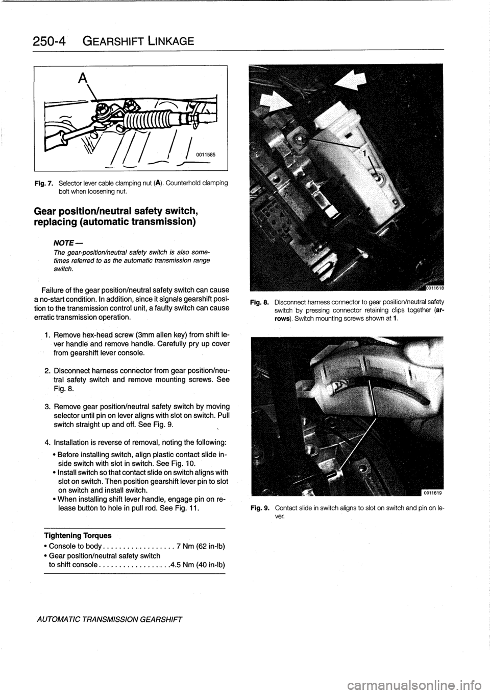
Loosen
selector
cable
clamping
nut
.
See
Fig
.
7
.
6
.
Lower
vehicle
.
Insta¡¡
shift
boot
cover
.
Push
shift
knob
4
.
Push
shift
lever
forwardtoward
engine(Park
position)
onto
lever
.
while
applying
light
pressure
on
cable
end
.
Tighten
ca-
ble
clamping
nut
.
Tightening
Torques
NOTE-
"
Driveshaft
to
final
drive
Do
not
overtighten
the
nut
so
that
it
twists
the
cable
.
flange
(with
U-joint)
.
..
.
.....
.
.
See
250
Driveshaft
"
Flex-disc
to
driveshaft
or
transmission
flange
...
.
.......
See
250
Driveshaft
Tightening
Torque
"
Transmission
crossmember
"
Shift
cable
clamping
nut
.......
10-12
Nm
(75-9
ft-Ib)
to
body
(M8)
.
.
.
...
..............
21
Nm
(16
ft-Ib)
/S
r\
1
1
Gear
position/
neutral
safetyswitch
Automatic
shilo
solenoid
id
AUTOMATIC
TRANSMISSION
GEARSHIFT
Page 238 of 759
250-
4
GEARSHIFT
LINKAGE
r%
;
5
(((((C
"
~
;
Fig
.
7
.
Selector
lever
cable
clamping
nut
(A)
.
Counterhold
clamping
bolt
when
loosening
nut
.
Gear
position/neutral
safety
switch,
replacing
(automatic
transmission)
NOTE-
The
gear-positionlneutral
safetyswitch
is
also
some-
times
referred
to
as
the
automatic
transmission
range
switch
.
Failure
of
the
gear
positionlneutral
safetyswitch
can
cause
a
no-start
condition
.
In
acidition,
since
it
signals
gearshift
posi-
tion
tothe
transmission
control
unit,
a
faulty
switch
can
cause
erratic
transmission
operation
.
1
.
Remove
hex-head
screw
(3mm
allen
key)
from
shift
le-
ver
handle
and
remove
handle
.
Carefully
pry
up
cover
from
gearshift
lever
console
.
2
.
Disconnect
harness
connector
from
gear
positionlneu-
tral
safety
switch
andremove
mounting
screws
.
See
Fig
.
8
.
3
.
Remove
gear
positionlneutral
safety
switch
by
moving
selector
until
pin
on
lever
aligns
with
slot
on
switch
.
Pull
switch
straight
up
and
off
.
See
Fig
.
9
.
4
.
Installation
is
reverse
of
removal,
noting
the
following
:
"
Before
installing
switch,
align
plastic
contact
slide
in-
sideswitch
with
slot
in
switch
.
See
Fig
.
10
.
"
Instan
switch
so
that
contact
slide
on
switch
aligns
with
slot
on
switch
.
Then
position
gearshift
lever
pin
to
slot
on
switch
and
install
switch
.
"
When
installing
shift
lever
handle,
engage
pín
on
re
leasebutton
to
hole
in
pulí
rod
.
See
Fig
.
11
.
Fig
.
9
.
Contact
slide
in
switch
aligns
toslot
on
switch
and
pin
on
le-
ver
.
Tightening
Torques
"
Console
to
body
..............
...
.
7
Nm
(62
in-lb)
"
Gear
positionlneutral
safety
switch
to
shift
console
.................
.
4
.5
Nm
(40
in-lb)
AUTOMATIC
TRANSMISSION
GEARSHIFT
Fig
.
8
.
Disconnect
harness
connector
to
gear
position/neutral
safety
switch
by
pressing
connector
retaining
clips
together
(ar-
rows)
.
Switch
mountingscrews
shown
at
1
.
Page 239 of 759

Fig
.
10
.
Align
contact
slide
(1)
with
slot
in
switch
housing
(2)
before
in-
stalling
gear
position/neutral
safety
switch
.
Fig
.
11
.
Engage
release
button
pin
to
hole
in
pull
rod
before
installing
The
automatic
shiftlock
uses
an
electríc
solenoid
to
lock
the
selector
lever
in
P
or
N
.
Depressing
the
foot
brake
withthe
ig-
nition
on
energizes
the
solenoid,
allowingthe
lever
to
be
moved
into
a
drive
gear
.
The
solenoid
is
energized
only
when
the
engine
speed
is
below
2,500
rpmand
thevehicle
speed
is
below
3
mph
.
The
solenoid
ís
mounted
in
the
right-hand
side
of
theselector
lever
housing
.
See
Fig
.
12
.
1
.
With
engine
running
and
car
stopped,
place
selector
le-
ver
in
P
or
N
.
2
.
Without
depressing
brake
pedal,
check
that
selector
le-
ver
is
locked
in
position
P
or
N
.
3
.
Depress
brakepedal
firmly
.
Solenoid
should
be
heard
to
energize
.
GEARSHIFT
LINKAGE
250-
5
Fig
.
12
.
Automatic
shiftlock
prevents
drive
gear
selection
until
the
brakepedal
is
depressed
.
4
.
Check
thatselector
lever
can
now
be
moved
out
of
P
or
N
.
NOTE
-
The
next
test
should
be
performed
in
anopen
area
with
the
parking
brake
on
and
with
extreme
caution
.
5
.
With
selector
lever
in
P
or
N
and
brake
pedal
de-
pressed,
raise
engine
above
2,500
rpm
.
Check
that
se-
lector
lever
cannotbe
moved
outof
P
or
N
.
shift
lever
handle
.
If
any
faults
are
found
check
the
electrical
operation
of
the
shiftlock
solenoid
and
check
for
wiring
faultsto
or
from
the
Automatic
shiftiock,
checking
function
transmission
control
module(TCM)
.
See610
Electrical
(automatic
transmission)
Component
Locations
and
Electrical
Wiring
Diagrams
.
NOTE
-
The
solenoid
is
controlled
viathe
TCM,
using
brakepedal
position,
engine
speed,
and
road
speed
as
con-
trolling
inputs
.
AUTOMATIC
TRANSMISSION
GEARSHIFT