Page 497 of 1202

P20488
EM9443
Plastigage
Z14291
4
810
6
2 159
73
EM9442
- ENGINE MECHANICALCYLINDER BLOCK
EM-75
1996 TERCEL (RM440U)
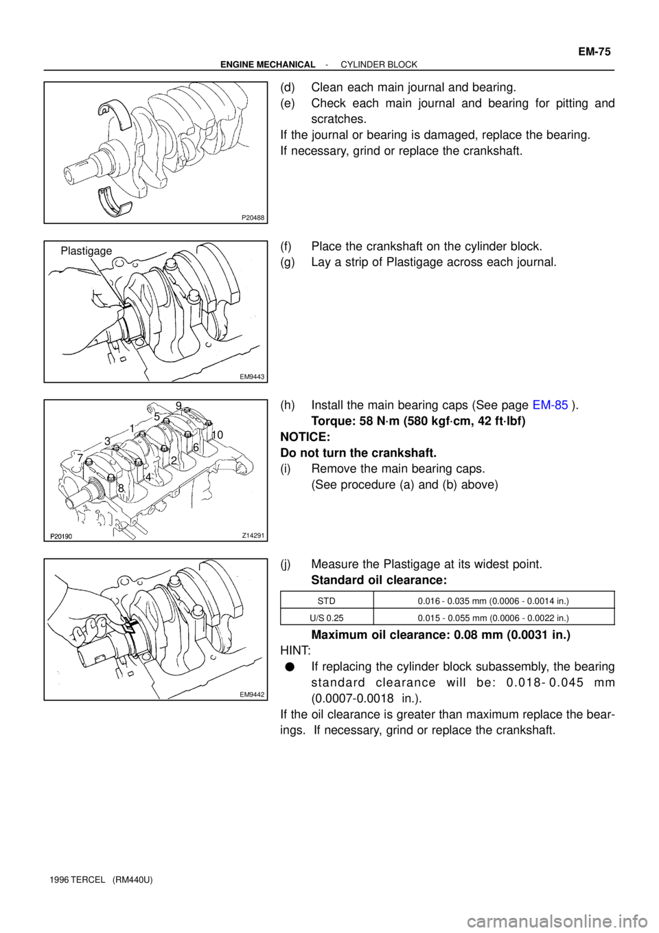
(d) Clean each main journal and bearing.
(e) Check each main journal and bearing for pitting and
scratches.
If the journal or bearing is damaged, replace the bearing.
If necessary, grind or replace the crankshaft.
(f) Place the crankshaft on the cylinder block.
(g) Lay a strip of Plastigage across each journal.
(h) Install the main bearing caps (See page EM-85).
Torque: 58 N´m (580 kgf´cm, 42 ft´lbf)
NOTICE:
Do not turn the crankshaft.
(i) Remove the main bearing caps.
(See procedure (a) and (b) above)
(j) Measure the Plastigage at its widest point.
Standard oil clearance:
STD0.016 - 0.035 mm (0.0006 - 0.0014 in.)
U/S 0.250.015 - 0.055 mm (0.0006 - 0.0022 in.)
Maximum oil clearance: 0.08 mm (0.0031 in.)
HINT:
�If replacing the cylinder block subassembly, the bearing
standard clearance will be: 0.018- 0.045 mm
(0.0007-0.0018 in.).
If the oil clearance is greater than maximum replace the bear-
ings. If necessary, grind or replace the crankshaft.
Page 499 of 1202
P20489
P20548
Z07984
SST SST
SST
SSTSSTPiston
Pin
SST
- ENGINE MECHANICALCYLINDER BLOCK
EM-77
1996 TERCEL (RM440U)
23. CHECK FIT BETWEEN PISTON AND PIN
Try to move the piston back and forth on the piston pin.
If any movement is felt, replace the piston and pin as a set.
24. REMOVE PISTON RINGS
(a) Using a piston ring expander, remove the compression
rings.
(b) Remove the 2 side rails and oil ring expander by hand.
HINT:
Arrange the rings in the correct order only.
25. DISCONNECT CONNECTING ROD FROM PISTON
(a) Using SST, press out the piston pin from the piston.
(b) Remove the connecting rod.
SST 09221-25024 (09221-00020, 09221-00030,
09221-00130, 09221-00140, 09221-00150)
HINT:
�The piston and pin are a matched set.
�Arrange the pistons, pins, rings, connecting rods and
bearings in correct order.
Page 503 of 1202

P20540
P20527
Top of Cylinder Block
110 mm
(4.33 in.,)
EM7639
N00301
- ENGINE MECHANICALCYLINDER BLOCK
EM-81
1996 TERCEL (RM440U)
8. INSPECT PISTON RING GROOVE CLEARANCE
Using a feeler gauge, measure the clearance between new pis-
ton ring and the wall of the ring groove.
Ring groove clearance:
No.10.04 - 0.08 mm (0.0016 - 0.0031 in.)
No.20.03 - 0.07 mm (0.0012 - 0.0028 in.)
If the oil clearance is greater than maximum, replace the piston.
9. INSPECT PISTON RING END GAP
(a) Insert the piston ring into the cylinder bore.
(b) Using a piston, push the piston ring a little beyond the bot-
tom of the ring travel, 110 mm (4.33 in.) from the top of the
cylinder block.
(c) Using a feeler gauge, measure the end gap.
Standard end gap:
No.10.26 - 0.48 mm (0.0102 - 0.0189 in.)
No.20.36 - 0.57 mm (0.0142 - 0.0224 in.)
Oil (Side rail)0.13 - 0.50 mm (0.0051 - 0.0197 in.)
Maximum end gap:
No.11.07 mm (0.0421 in.)
No.21.02 mm (0.0402 in.)
Oil (Side rail)1.10 mm (0.0433 in.)
If the end gap is greater than maximum, replace the piston ring.
If necessary, replace the cylinder block.
10. INSPECT CONNECTING RODS
Using a rod aligner, check the connecting rod alignment.
�Check for out-of-alignment.
Maximum out-of-alignment:
0.03 mm (0.0012 in.) per 100 mm (3.94 in.)
If out-of-alignment is greater than maximum, replace the con-
necting rod assembly.
Page 504 of 1202

N00302
EM3208
N00295
EM-82
- ENGINE MECHANICALCYLINDER BLOCK
1996 TERCEL (RM440U)
�Check for twist
Maximum twist:
0.05 mm (0.0020 in.) per 100 mm (3.94 in.)
If twist is greater than maximum, replace the connecting rod as-
sembly.
HINT:
If replacing the connection rods, replace the same number of
connecting rod bearings as that of new connecting rod caps.
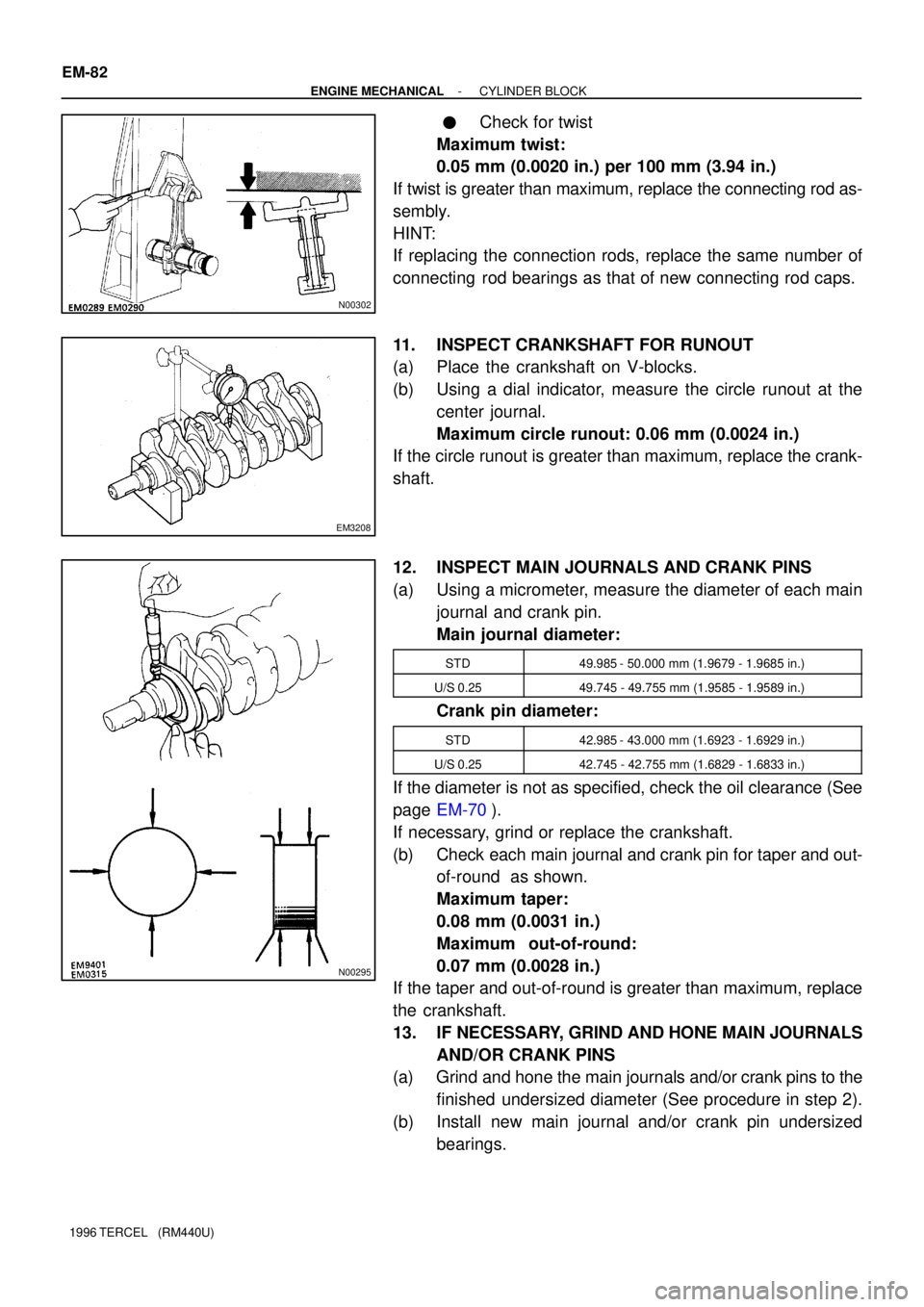
11. INSPECT CRANKSHAFT FOR RUNOUT
(a) Place the crankshaft on V-blocks.
(b) Using a dial indicator, measure the circle runout at the
center journal.
Maximum circle runout: 0.06 mm (0.0024 in.)
If the circle runout is greater than maximum, replace the crank-
shaft.
12. INSPECT MAIN JOURNALS AND CRANK PINS
(a) Using a micrometer, measure the diameter of each main
journal and crank pin.
Main journal diameter:
STD49.985 - 50.000 mm (1.9679 - 1.9685 in.)
U/S 0.2549.745 - 49.755 mm (1.9585 - 1.9589 in.)
Crank pin diameter:
STD42.985 - 43.000 mm (1.6923 - 1.6929 in.)
U/S 0.2542.745 - 42.755 mm (1.6829 - 1.6833 in.)
If the diameter is not as specified, check the oil clearance (See
page EM-70).
If necessary, grind or replace the crankshaft.
(b) Check each main journal and crank pin for taper and out-
of-round as shown.
Maximum taper:
0.08 mm (0.0031 in.)
Maximum out-of-round:
0.07 mm (0.0028 in.)
If the taper and out-of-round is greater than maximum, replace
the crankshaft.
13. IF NECESSARY, GRIND AND HONE MAIN JOURNALS
AND/OR CRANK PINS
(a) Grind and hone the main journals and/or crank pins to the
finished undersized diameter (See procedure in step 2).
(b) Install new main journal and/or crank pin undersized
bearings.
Page 507 of 1202

EM0JT-05
P20471
Front Mark
(Cavity)
Front Mark
(Protrusion)
Z08055
SST
Piston Pin
SSTSST
SST
SST
SST SST
P20549
P20560
1R
2R
- ENGINE MECHANICALCYLINDER BLOCK
EM-85
1996 TERCEL (RM440U)
REASSEMBLY
HINT:
�Thoroughly clean all parts to be assembled.
�Before installing the parts, apply new engine oil to all slid-
ing and rotating surfaces.
�Replace all gaskets, O-rings and oil seals with new parts.
1. ASSEMBLE PISTON AND CONNECTING ROD
(a) Coat the piston pin and pin holes of the piston with engine
oil.
(b) Align the cavity on the piston with the protrusion on the
connecting rod.
(c) Using SST, press in the piston pin.
SST 09221-25025 (09221-00020, 09221-00030,
09221-00130, 09221-00140, 09221-00150)
(d) After installing the piston pin, check that when the con-
necting rod is aligned with the center of the piston the
space between the piston and each end of the piston pin
are equal on the left and right sides.
HINT:
If the piston pin is off-center due to insufficient insertion pres-
sure on the piston pin, place a washer at the position indicated
by � in the illustration for (c). Then, while checking that the
space is equal at the ends of the piston pin on the left and right
sides, press in the washer.
2. INSTALL PISTON RINGS
(a) Install the oil ring expander and 2 side rails by hand.
(b) Using a piston ring expander, install the 2 compression
rings with the code mark facing upward.
Code Mark:
No.11R
No.22R
Page 509 of 1202

P20551
P20530
Front
Z14291
1
2 3
45
6
7
89
10
EM3480
P20569
Front Mark
(Cavity)
FrontPush
- ENGINE MECHANICALCYLINDER BLOCK
EM-87
1996 TERCEL (RM440U)
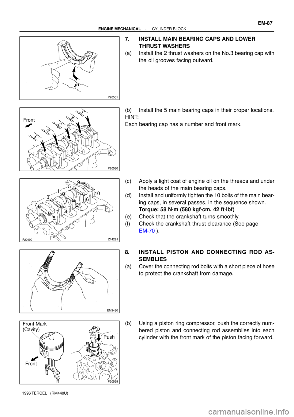
7. INSTALL MAIN BEARING CAPS AND LOWER
THRUST WASHERS
(a) Install the 2 thrust washers on the No.3 bearing cap with
the oil grooves facing outward.
(b) Install the 5 main bearing caps in their proper locations.
HINT:
Each bearing cap has a number and front mark.
(c) Apply a light coat of engine oil on the threads and under
the heads of the main bearing caps.
(d) Install and uniformly tighten the 10 bolts of the main bear-
ing caps, in several passes, in the sequence shown.
Torque: 58 N´m (580 kgf´cm, 42 ft´lbf)
(e) Check that the crankshaft turns smoothly.
(f) Check the crankshaft thrust clearance (See page
EM-70).
8. INSTALL PISTON AND CONNECTING ROD AS-
SEMBLIES
(a) Cover the connecting rod bolts with a short piece of hose
to protect the crankshaft from damage.
(b) Using a piston ring compressor, push the correctly num-
bered piston and connecting rod assemblies into each
cylinder with the front mark of the piston facing forward.
Page 510 of 1202

EM3481
Front Mark
(Protrusion)
Front
EM3448
P20475
Seal Packing
A'B'
A
B
A - A' B - B' EM-88
- ENGINE MECHANICALCYLINDER BLOCK
1996 TERCEL (RM440U)
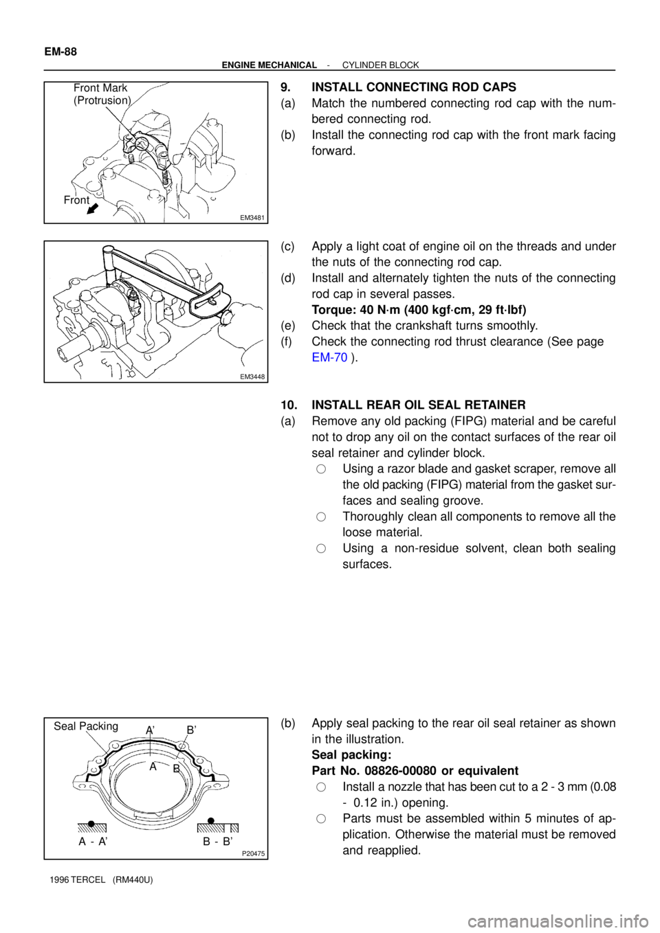
9. INSTALL CONNECTING ROD CAPS
(a) Match the numbered connecting rod cap with the num-
bered connecting rod.
(b) Install the connecting rod cap with the front mark facing
forward.
(c) Apply a light coat of engine oil on the threads and under
the nuts of the connecting rod cap.
(d) Install and alternately tighten the nuts of the connecting
rod cap in several passes.
Torque: 40 N´m (400 kgf´cm, 29 ft´lbf)
(e) Check that the crankshaft turns smoothly.
(f) Check the connecting rod thrust clearance (See page
EM-70).
10. INSTALL REAR OIL SEAL RETAINER
(a) Remove any old packing (FIPG) material and be careful
not to drop any oil on the contact surfaces of the rear oil
seal retainer and cylinder block.
�Using a razor blade and gasket scraper, remove all
the old packing (FIPG) material from the gasket sur-
faces and sealing groove.
�Thoroughly clean all components to remove all the
loose material.
�Using a non-residue solvent, clean both sealing
surfaces.
(b) Apply seal packing to the rear oil seal retainer as shown
in the illustration.
Seal packing:
Part No. 08826-00080 or equivalent
�Install a nozzle that has been cut to a 2 - 3 mm (0.08
- 0.12 in.) opening.
�Parts must be assembled within 5 minutes of ap-
plication. Otherwise the material must be removed
and reapplied.
Page 526 of 1202

SF1PQ-02
- MFIMFI SYSTEM
MF-1
525 Author�: Date�:
1996 TERCEL (RM440U)
MFI SYSTEM
PRECAUTION
1. BEFORE WORKING ON FUEL SYSTEM, DISCON-
NECT NEGATIVE (-) TERMINAL CABLE FROM BAT-
TERY
HINT:
Any diagnostic trouble code retained by the computer will be
erased when the negative (-) terminal cable is disconnected.
Therefore, if necessary, read the diagnosis before disconnect-
ing the negative (-) terminal cable from the battery.
2. DO NOT SMOKE OR WORK NEAR AN OPEN FLAME
WHEN WORKING ON THE FUEL SYSTEM
3. KEEP GASOLINE AWAY FROM RUBBER OR LEATH-
ER PARTS
4. MAINTENANCE PRECAUTIONS
(a) In event of engine misfire, the following precautions
should be taken.
(1) Check proper connection to battery terminals, etc.
(2) Handle higt-tension cords carefully.
(3) After repair work, check that the ignition coil termi-
nals and all other ignition system lines are recon-
nected securely.
(4) When cleaning the engine compartment, be espe-
cially careful to protect the electrical system from
water.
(b) Precautions when handling the oxygen sensor.
(1) Do not allow the oxygen sensor to drop or hit
against an object.
(2) Do not allow the sensor to come into contact with
water.
5. IF VEHICLE IS EQUIPPED WITH MOBILE RADIO SYS-
TEM (HAM, CB, ETC.)
If the vehicle is equipped with a mobile communication system,
refer to the precaution in the IN section.
6. AIR INDUCTION SYSTEM
(a) Separation of the engine oil dipstick, oil filler cap, PCV
hose, etc. may cause the engine out of tune.
(b) Disconnection, looseness or cracks in the parts of the air
induction system between the throttle body and cylinder
head will cause air suction and cause the engine out of
tune.
7. ELECTRONIC CONTROL SYSTEM
(a) Before removing MFI wiring connectors, terminals, etc.,
first disconnect the power by either turning the ignition
switch to LOCK or disconnecting the negative (-) terminal
cable from the battery.