Page 948 of 1202

SR0KY-02
R11074
SST
SR4244
- STEERINGPOWER STEERING GEAR
SR-49
1996 TERCEL (RM440U)
REMOVAL
1. PLACE FRONT WHEELS FACING STRAIGHT AHEAD
2. w/ Airbag:
REMOVE STEERING WHEEL PAD (See page SR-13)
3. w/ Airbag:
REMOVE STEERING WHEEL (See page SR-13)
4. DISCONNECT RH AND LH TIE ROD ENDS (See page
SA-10)
5. REMOVE COLUMN HOLE COVER
Remove the 2 bolts and nut.
6. DISCONNECT SLIDING YOKE (See page SR-13)
7. REMOVE OXYGEN SENSOR
8. REMOVE FRONT EXHAUST PIPE
(a) Remove the 2 bolts, compression springs and gasket.
(b) Remove the bolt, clamp and gasket.
(c) Disconnect the 2 rings.
9. REMOVE ENGINE REAR MOUNT INSULATOR
Remove the 6 bolts.
10. REMOVE ENGINE REAR MOUNT BRACKET
Remove the 2 bolts.
11. DISCONNECT 2 VACUUM HOSES
12. M/T:
DISCONNECT CONTROL CABLES
(a) Remove the 2 clips and washers.
(b) Remove the 2 clips from the cables.
(c) Disconnect the 2 cables from the control lever housing
support bracket.
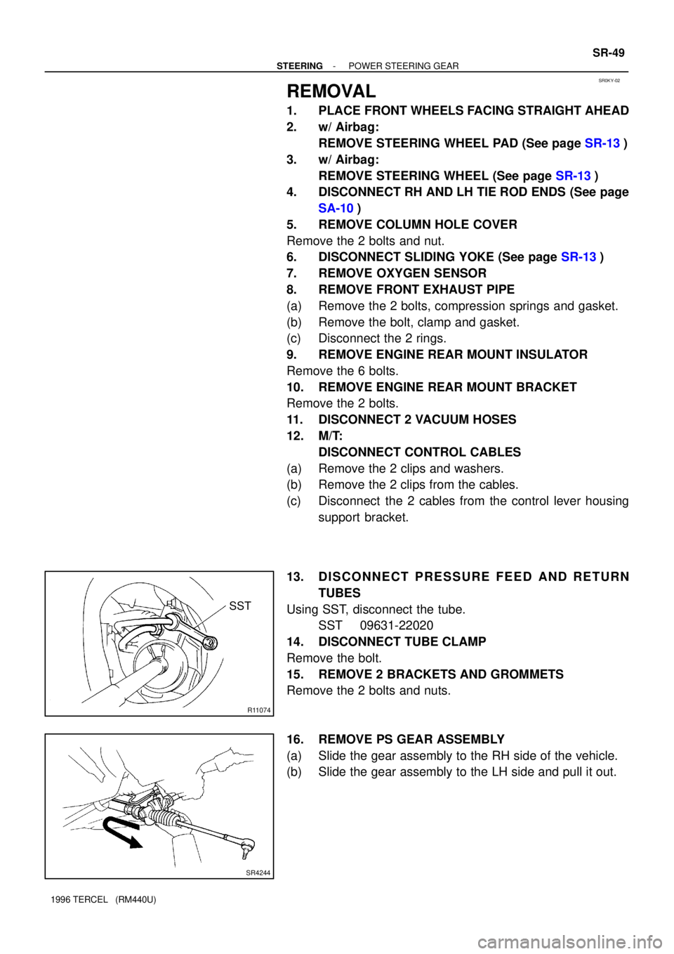
13. DISCONNECT PRESSURE FEED AND RETURN
TUBES
Using SST, disconnect the tube.
SST 09631-22020
14. DISCONNECT TUBE CLAMP
Remove the bolt.
15. REMOVE 2 BRACKETS AND GROMMETS
Remove the 2 bolts and nuts.
16. REMOVE PS GEAR ASSEMBLY
(a) Slide the gear assembly to the RH side of the vehicle.
(b) Slide the gear assembly to the LH side and pull it out.
Page 962 of 1202

- STEERINGPOWER STEERING GEAR
SR-63
1996 TERCEL (RM440U)
9. INSTALL FRONT EXHAUST PIPE
(a) Connect the 2 rings.
(b) Install the bolt and clamp over a new gasket.
Torque: 19 N´m (190 kgf´cm, 14 ft´lbf)
(c) Install the 2 bolts and compression springs over a new
gasket.
Torque: 62 N´m (630 kgf´cm, 46 ft´lbf)
10. INSTALL OXYGEN SENSOR
Install the sensor.
Torque: 44 N´m (450 kgf´cm, 32 ft´lbf)
11. CONNECT SLIDING YOKE (See page SR-20)
12. INSTALL COLUMN HOLE COVER
Torque the 2 bolts and nut.
Torque: 4.9 N´m (50 kgf´cm, 43 in.´lbf)
13. CONNECT RH AND LH TIE ROD ENDS
(See page SA-10)
14. PLACE FRONT WHEELS FACING STRAIGHT AHEAD
HINT:
Do it with the front of the vehicle jacked up.
15. w/ Airbag:
CENTER SPIRAL CABLE (See page SR-20)
16. w/ Airbag:
INSTALL STEERING WHEEL
(a) Install the wheel at straight-ahead position.
(b) Temporarily tighten the wheel set nut.
(c) Connect the connector.
17. BLEED POWER STEERING SYSTEM
(See page SR-5)
18. CHECK STEERING WHEEL CENTER POINT
19. w/ Airbag:
TORQUE STEERING WHEEL SET NUT
Torque: 34 N´m (350 kgf´cm, 25 ft´lbf)
20. w/ Airbag:
INSTALL STEERING WHEEL PAD (See page SR-20)
21. CHECK FRONT WHEEL ALIGNMENT
(See page SA-4)
Page 976 of 1202

AB0163
Wire Harness
Diameter
Stripped Wire Harness Section
RS-14
- SUPPLEMENTAL RESTRAINT SYSTEMSTEERING WHEEL PAD AND SPIRAL CABLE
1996 TERCEL (RM440U)
CAUTION:
When storing the steering wheel pad, keep the deployment
direction facing up.
(b) Fix the steering wheel pad.
(1) Using a service-purpose wire harness for the ve-
hicle tie down the steering wheel pad to the disc
wheel
Wire harness: Stripped wire harness section
1.25 mm
2 or more (0.0019 in.2 or more).
CAUTION:
If a wire harness which is too thin or some other thing is
used to tie down the steering wheel pad, it may be snapped
by the shock when the airbag is deployed. This is highly
dangerous. Always use a wire harness for vehicle use
which is at least 1.25 mm
2 (0.0019 in.2).
HINT:
To calculate the square of the stripped wire harness section:
Square = 3.14 X (Diameter)
2 divided by 4
(2) Remove the connector on the steering wheel pad
rear surface from the inflater cover.
(3) Install the bolts and washers in the 3 bolt holes in
the steering wheel pad.
Bolt:
L: 35.0 mm (1.387 in.)
M: 6.0 mm (0.236 in.)
Pitch: 1.0 mm (0.039 in.)
NOTICE:
�Tighten the bolts by hand until the bolts become diffi-
cult to turn.
�Do not tighten the bolts too much.
Page 977 of 1202

R05751
AB0158
Battery
SST
- SUPPLEMENTAL RESTRAINT SYSTEMSTEERING WHEEL PAD AND SPIRAL CABLE
RS-15
1996 TERCEL (RM440U)
(4) Using 3 wire harness, wrap the wire harness at least
2 times each around the bolts installed on the left
and right sides of the steering wheel pad.
CAUTION:
�Tightly wind the wire harness around the bolts so that
there is no slack.
�If there is slackness in the wire harness, the steering
wheel pad may come loose due to the shock when the
airbag is deployed. This is highly dangerous.
(5) Face the upper surface of the steering wheel pad
upward. Separately tie the left and right sides of the
steering wheel pad to the disc wheel through the
hub nut holes.
(6) Position the steering wheel pad connector so that
it hangs downward through a hub hole in the disc
wheel.
CAUTION:
�Make sure that the wire harness is tight. It is very dan-
gerous if looseness in the wire harness results in the
steering wheel pad coming free through the shock of
the airbag deploying.
�Always tie down the steering wheel pad with the pad
side facing upward. It is very dangerous if the steer-
ing wheel pad is tied down with the metal surface fac-
ing to the airbag deploying direction and the steering
wheel pad will be thrown into the air.
HINT:
The disc wheel will be marked by airbag deployment, so when
disposing of the airbag use a redundant disc wheel.
(c) Check functioning of the SST.
(See step 1)
SST 09082-00700
Page 1119 of 1202

BO347-01
N12292
N12291
N12055
BO-48
- BODYINSTRUMENT PANEL
1996 TERCEL (RM440U)
REMOVAL
1. REMOVE FRONT PILLAR GARNISHES
2. REMOVE COWL SIDE TRIMS
3. REMOVE FRONT DOOR SCUFF PLATES
4. REMOVE STEERING WHEEL (See page SR-13)
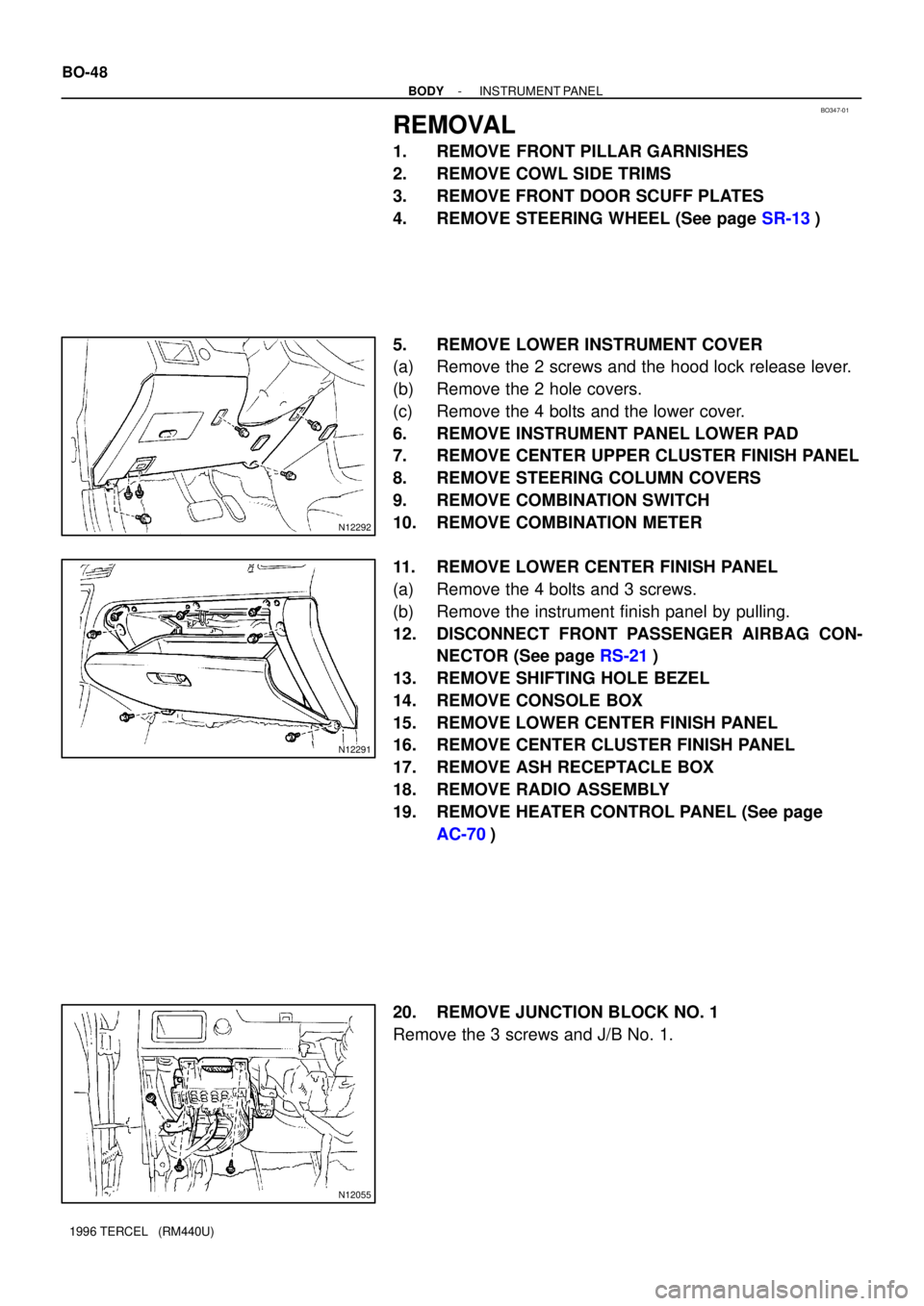
5. REMOVE LOWER INSTRUMENT COVER
(a) Remove the 2 screws and the hood lock release lever.
(b) Remove the 2 hole covers.
(c) Remove the 4 bolts and the lower cover.
6. REMOVE INSTRUMENT PANEL LOWER PAD
7. REMOVE CENTER UPPER CLUSTER FINISH PANEL
8. REMOVE STEERING COLUMN COVERS
9. REMOVE COMBINATION SWITCH
10. REMOVE COMBINATION METER
11. REMOVE LOWER CENTER FINISH PANEL
(a) Remove the 4 bolts and 3 screws.
(b) Remove the instrument finish panel by pulling.
12. DISCONNECT FRONT PASSENGER AIRBAG CON-
NECTOR (See page RS-21)
13. REMOVE SHIFTING HOLE BEZEL
14. REMOVE CONSOLE BOX
15. REMOVE LOWER CENTER FINISH PANEL
16. REMOVE CENTER CLUSTER FINISH PANEL
17. REMOVE ASH RECEPTACLE BOX
18. REMOVE RADIO ASSEMBLY
19. REMOVE HEATER CONTROL PANEL (See page
AC-70)
20. REMOVE JUNCTION BLOCK NO. 1
Remove the 3 screws and J/B No. 1.
Page:
< prev 1-8 9-16 17-24