Page 1131 of 1354
SA0TE−01
R10733
SST
R10759
− SUSPENSION AND AXLEFRONT WHEEL HUB BOLT
SA−17
1996 RAV4 (RM447U)
FRONT WHEEL HUB BOLT
REPLACEMENT
1. REMOVE FRONT WHEEL
2. REMOVE FRONT BRAKE CALIPER AND DISC
(a) Remove the 2 bolts and brake caliper from the steering
knuckle.
(b) Support the brake caliper securely and remove the disc.
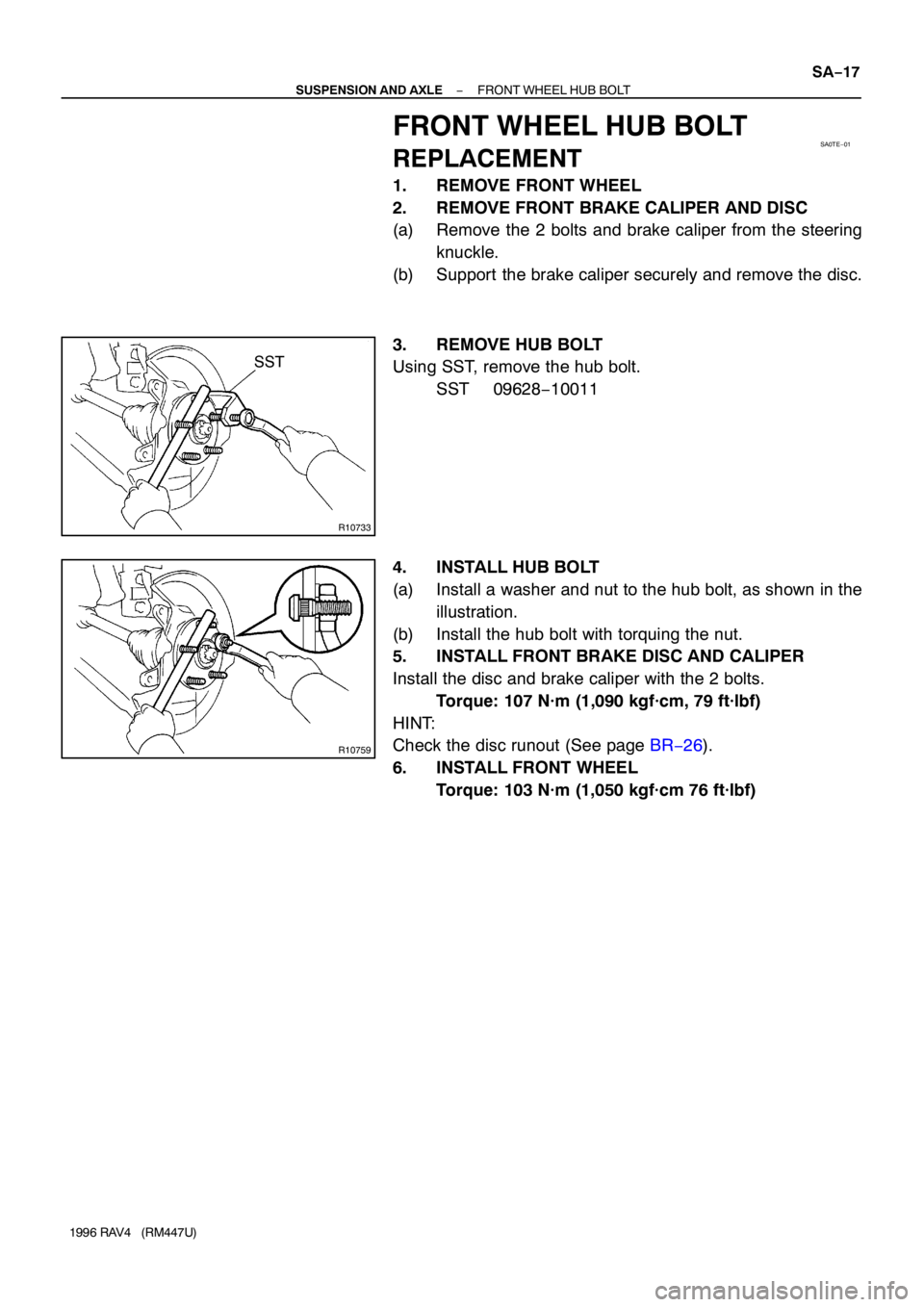
3. REMOVE HUB BOLT
Using SST, remove the hub bolt.
SST 09628−10011
4. INSTALL HUB BOLT
(a) Install a washer and nut to the hub bolt, as shown in the
illustration.
(b) Install the hub bolt with torquing the nut.
5. INSTALL FRONT BRAKE DISC AND CALIPER
Install the disc and brake caliper with the 2 bolts.
Torque: 107 N·m (1,090 kgf·cm, 79 ft·lbf)
HINT:
Check the disc runout (See page BR−26).
6. INSTALL FRONT WHEEL
Torque: 103 N·m (1,050 kgf·cm 76 ft·lbf)
Page 1188 of 1354
SA0UK−01
R10640
R10650
F03752
Hold
R10645
SA−74
− SUSPENSION AND AXLEREAR DIFFERENTIAL CARRIER
1996 RAV4 (RM447U)
DISASSEMBLY
1. REMOVE DIFFERENTIAL CARRIER COVER
(a) Remove the 8 bolts from the carrier cover.
(b) Using a brass bar and hammer, separate the cover and
carrier.
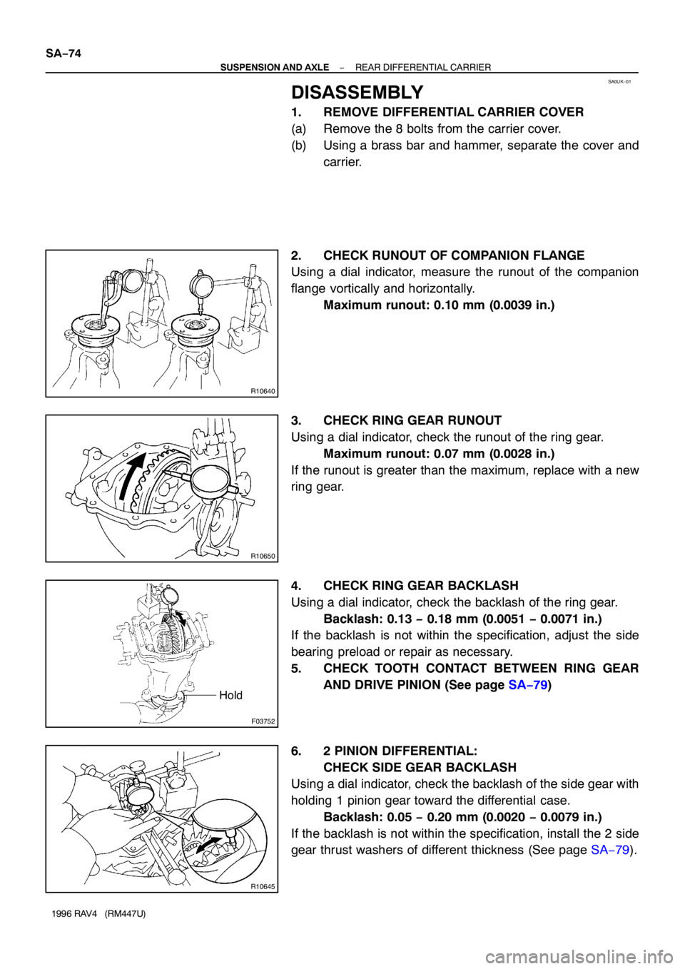
2. CHECK RUNOUT OF COMPANION FLANGE
Using a dial indicator, measure the runout of the companion
flange vortically and horizontally.
Maximum runout: 0.10 mm (0.0039 in.)
3. CHECK RING GEAR RUNOUT
Using a dial indicator, check the runout of the ring gear.
Maximum runout: 0.07 mm (0.0028 in.)
If the runout is greater than the maximum, replace with a new
ring gear.
4. CHECK RING GEAR BACKLASH
Using a dial indicator, check the backlash of the ring gear.
Backlash: 0.13 − 0.18 mm (0.0051 − 0.0071 in.)
If the backlash is not within the specification, adjust the side
bearing preload or repair as necessary.
5. CHECK TOOTH CONTACT BETWEEN RING GEAR
AND DRIVE PINION (See page SA−79)
6. 2 PINION DIFFERENTIAL:
CHECK SIDE GEAR BACKLASH
Using a dial indicator, check the backlash of the side gear with
holding 1 pinion gear toward the differential case.
Backlash: 0.05 − 0.20 mm (0.0020 − 0.0079 in.)
If the backlash is not within the specification, install the 2 side
gear thrust washers of different thickness (See page SA−79).
Page 1195 of 1354

F03759
SST
F03760
W01226
SST SST FrontRear
− SUSPENSION AND AXLEREAR DIFFERENTIAL CARRIER
SA−81
1996 RAV4 (RM447U) 1/17/01
4. INSTALL SIDE BEARINGS
Using SST and a press, install the 2 side bearings into the differ-
ential case.
SST 09710−22021 (09710−01031)
5. INSPECT RING GEAR RUNOUT
(a) Install the differential case on the carrier, and install the
2 plate washers to fill the no play in the bearing.
(b) Install the bearing caps (See page SA−79).
(c) Using a dial indicator, measure the runout of the ring gear.
Maximum runout: 0.07 mm (0.0028 in.)
(d) Remove the 2 bearing caps, 2 plate washers and differen-
tial carrier (See page SA−74).
6. INSTALL FRONT AND REAR BEARING OUTER
RACES
(a) Front side:
Using SST and a press, install the 2 outer races to the car-
rier.
SST 09950−60020 (09951−00790),
09950−70010 (09951−07150)
(b) Rear side:
Using SST and a press, install the 2 outer races to the car-
rier.
SST 09950−60020 (09951−00710),
09950−70010 (09951−07150)
7. INSTALL DRIVE PINION REAR BEARING
(a) Install the reused washer on the drive pinion.
Page 1201 of 1354

R10768
SST
R10641
W01227
SST
− SUSPENSION AND AXLEREAR DIFFERENTIAL CARRIER
SA−87
1996 RAV4 (RM447U) 1/17/01
(c) Using SST to hold the flange, torque the nut.
SST 09330−00021
Torque: 108 N·m (1,100 kgf·cm, 80 ft·lbf)
20. CHECK DRIVE PINION PRELOAD
(a) Using a torque wrench, measure the preload of the back-
lash between the drive pinion and ring gear.
Preload (at starting):
New bearing:
1.0 − 1.6 N·m (10 − 16 kgf·cm, 8.7 − 13.9 in.·lbf)
Reused bearing:
0.5 − 0.8 N·m (5 − 8 kgf·cm, 4.3 − 6.9 in.·lbf)
If preload is larger than the specification, replace the bearing
spacer.
If preload is less than the specification, retorque the nut 13 N·m
(130 kgf·cm, 9 ft·lbf) at a time until the specified preload is
reached.
Torque: 235 N·m (2,400 kgf·cm, 174 ft·lbf) or less
If the maximum torque is exceeded while retighten the nut, re-
place the bearing spacer and repeat the preload procedure. Do
not loosen the pinion nut to reduce the preload.
21. RECHECK TOTAL PRELOAD (See page SA−74)
22. RECHECK RING GEAR BACKLASH
(See page SA−74)
23. RECHECK TOOTH CONTACT BETWEEN RING GEAR
AND DRIVE PINION (See page SA−79)
24. CHECK COMPANION FLANGE RUNOUT
(See page SA−74)
25. STAKE DRIVE PINION NUT
26. INSTALL SIDE GEAR SHAFT OIL SEALS
(a) Using SST and a hammer, install 2 oil seals until they are
flush with the carrier end surface.
SST 09550−00032, 09950−70010 (09951−07150)
(b) Coat MP grease to the oil seal lip.
27. Torque Sensing LSD:
INSTALL SIDE GEAR SHAFTS
Page 1325 of 1354

SR0G4−03
R10072
Dial Indicator
W01250
Cylinder Gauge
Bushing
Micrometer
W03557
SST
Bushing SST
R11295
Vinyl Tape
Oil Seal
− STEERINGPOWER STEERING GEAR
SR−51
1996 RAV4 (RM447U)
INSPECTION
NOTICE:
When using a vise, do not overtighten it.
1. INSPECT STEERING RACK
(a) Using a dial indicator, check the rack for runout.
Maximum runout: 0.30 mm (0.0118 in.)
(b) Check the rack for teeth wear and damage.
(c) Check the back surface for wear and damage.
2. CHECK CONTROL VALVE ASSEMBLY AND BUSHING
Using a cylinder gauge and a micrometer, measure the inside
diameter of the bushing and outside diameter of the valve as-
sembly.
Maximum inside diameter: 28.20 mm (1.1102 in.)
Minimum outside diameter: 27.75 mm (1.0925 in.)
3. IF NECESSARY, REPLACE BUSHING AND OIL SEAL
(a) Using SST, remove the bushing from the rack housing.
SST 09612−24014 (09613−22011)
NOTICE:
Be careful not to damage the rack housing.
HINT:
�Separate the SST as shown in the illustration to use it.
�As shown, from the opposite side of SST confirm that its
claw is firmly caught on the bushing.
(b) Using a screwdriver, tap out the oil seal.
NOTICE:
To prevent rack housing damage, wind vinyl tape on the
screwdriver.
Page 1342 of 1354

P10584
Ohmmeter
Continuity
ST0N6−01
P10585
Ohmmeter
No Continuity
P10586
P10587
ST0040
− STARTINGSTARTER
ST−7
1996 RAV4 (RM447U)
INSPECTION
1. INSPECT ARMATURE COIL COMMUTATOR FOR
OPEN CIRCUIT
Using an ohmmeter, check that there is continuity between the
segments of the commutator.
If there is no continuity between any segment, replace the ar-
mature.
2. INSPECT ARMATURE COIL COMMUTATOR FOR
GROUND
Using an ohmmeter, check that there is no continuity between
the commutator and armature coil core.
If there is continuity, replace the armature.
3. INSPECT COMMUTATOR FOR DIRTY AND BURNT
SURFACES
If the surface is dirty or burnt, correct it with sandpaper (No.400)
or on a lathe.
4. INSPECT COMMUTATOR CIRCLE RUNOUT
(a) Place the commutator on V−blocks.
(b) Using a dial gauge, measure the circle runout.
Maximum circle runout: 0.05 mm (0.0020 in.)
If the circle runout is greater than maximum, correct it on a lathe.
5. INSPECT COMMUTATOR DIAMETER
Using a vernier caliper, measure the commutator diameter.
Standard diameter: 30.0 mm (1.181 in.)
Minimum diameter: 29.0 mm (1.142 in.)
If the diameter is less than minimum, replace the armature.
6. INSPECT UNDERCUT DEPTH
Check that the undercut depth is clean and free of foreign mate-
rials. Smooth out the edge.
Standard undercut depth: 0.6 mm (0.024 in.)
Minimum undercut depth: 0.2 mm (0.008 in.)
If the undercut depth is less than minimum, correct it with a
hacksaw blade.
Page:
< prev 1-8 9-16 17-24