Page 1639 of 2890
B6M0554
2) Remove battery.
B6M0555A
3) Remove #2 spark plug cord by pulling boot, not cord
itself.
B6M0556
4) Remove spark plug with the spark plug socket.
5) Installation is in the reverse order of removal.
Tightening torque (Spark plug):
20.6±2.9 N⋅m (2.10±0.30 kg-m, 15.19±2.14 ft-lb)
G6M0095
3. #3 SPARK PLUG
1) Disconnect battery ground cable.
25
6-1SERVICE PROCEDURE
3. Spark Plug
Page 1640 of 2890
B6M0557A
2) Disconnect mass air flow sensor connector.
3) Remove four clips securing air cleaner upper cover.
B6M0558
4) Loosen the clamp screw and separate air cleaner upper
cover from air intake duct.
5) Remove air cleaner element.
B6M0559A
6) Remove #3 spark plug cord by pulling boot, not cord
itself.
B6M0560
7) Remove spark plug with the spark plug socket.
8) Installation is in the reverse order of removal.
Tightening torque (Spark plug):
20.6±2.9 N⋅m (2.10±0.30 kg-m, 15.19±2.14 ft-lb)
26
6-1SERVICE PROCEDURE
3. Spark Plug
Page 1642 of 2890
B6M0563A
6) Remove #4 spark plug cord by pulling boot, not cord
itself.
B6M0564
7) Remove spark plug with the spark plug socket.
8) Installation is in the reverse order of removal.
Tightening torque (Spark plug):
20.6±2.9 N⋅m (2.10±0.30 kg-m, 15.19±2.14 ft-lb)
CAUTION:
The above torque should be only applied to new spark
plugs without oil on their threads.
In case their threads are lubricated, the torque should
be reduced by approximately 1/3 of the specified
torque in order to avoid over-stressing.
E: REMOVAL (2500 cc OUTBACK MODEL)
CAUTION:
All spark plugs installed on an engine, must be of the
same heat range.
Spark plug:
NGK: PFR5B-11
G6M0095
1. #1 SPARK PLUG
1) Disconnect battery ground cable.
28
6-1SERVICE PROCEDURE
3. Spark Plug
Page 1648 of 2890

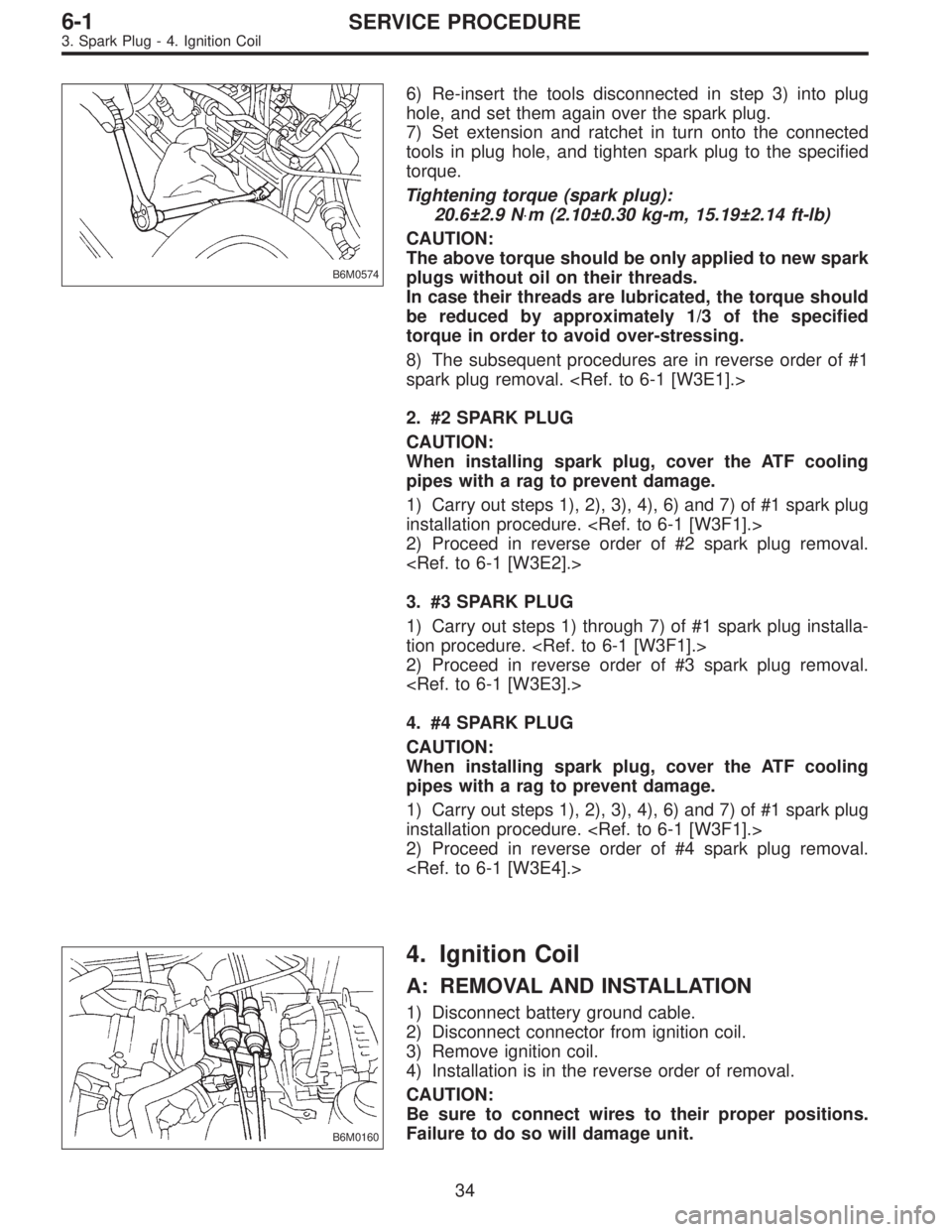
B6M0574
6) Re-insert the tools disconnected in step 3) into plug
hole, and set them again over the spark plug.
7) Set extension and ratchet in turn onto the connected
tools in plug hole, and tighten spark plug to the specified
torque.
Tightening torque (spark plug):
20.6±2.9 N⋅m (2.10±0.30 kg-m, 15.19±2.14 ft-lb)
CAUTION:
The above torque should be only applied to new spark
plugs without oil on their threads.
In case their threads are lubricated, the torque should
be reduced by approximately 1/3 of the specified
torque in order to avoid over-stressing.
8) The subsequent procedures are in reverse order of #1
spark plug removal.
2. #2 SPARK PLUG
CAUTION:
When installing spark plug, cover the ATF cooling
pipes with a rag to prevent damage.
1) Carry out steps 1), 2), 3), 4), 6) and 7) of #1 spark plug
installation procedure.
2) Proceed in reverse order of #2 spark plug removal.
3. #3 SPARK PLUG
1) Carry out steps 1) through 7) of #1 spark plug installa-
tion procedure.
2) Proceed in reverse order of #3 spark plug removal.
4. #4 SPARK PLUG
CAUTION:
When installing spark plug, cover the ATF cooling
pipes with a rag to prevent damage.
1) Carry out steps 1), 2), 3), 4), 6) and 7) of #1 spark plug
installation procedure.
2) Proceed in reverse order of #4 spark plug removal.
B6M0160
4. Ignition Coil
A: REMOVAL AND INSTALLATION
1) Disconnect battery ground cable.
2) Disconnect connector from ignition coil.
3) Remove ignition coil.
4) Installation is in the reverse order of removal.
CAUTION:
Be sure to connect wires to their proper positions.
Failure to do so will damage unit.
34
6-1SERVICE PROCEDURE
3. Spark Plug - 4. Ignition Coil
Page 1649 of 2890

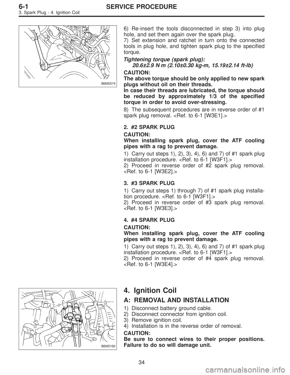
B6M0574
6) Re-insert the tools disconnected in step 3) into plug
hole, and set them again over the spark plug.
7) Set extension and ratchet in turn onto the connected
tools in plug hole, and tighten spark plug to the specified
torque.
Tightening torque (spark plug):
20.6±2.9 N⋅m (2.10±0.30 kg-m, 15.19±2.14 ft-lb)
CAUTION:
The above torque should be only applied to new spark
plugs without oil on their threads.
In case their threads are lubricated, the torque should
be reduced by approximately 1/3 of the specified
torque in order to avoid over-stressing.
8) The subsequent procedures are in reverse order of #1
spark plug removal.
2. #2 SPARK PLUG
CAUTION:
When installing spark plug, cover the ATF cooling
pipes with a rag to prevent damage.
1) Carry out steps 1), 2), 3), 4), 6) and 7) of #1 spark plug
installation procedure.
2) Proceed in reverse order of #2 spark plug removal.
3. #3 SPARK PLUG
1) Carry out steps 1) through 7) of #1 spark plug installa-
tion procedure.
2) Proceed in reverse order of #3 spark plug removal.
4. #4 SPARK PLUG
CAUTION:
When installing spark plug, cover the ATF cooling
pipes with a rag to prevent damage.
1) Carry out steps 1), 2), 3), 4), 6) and 7) of #1 spark plug
installation procedure.
2) Proceed in reverse order of #4 spark plug removal.
B6M0160
4. Ignition Coil
A: REMOVAL AND INSTALLATION
1) Disconnect battery ground cable.
2) Disconnect connector from ignition coil.
3) Remove ignition coil.
4) Installation is in the reverse order of removal.
CAUTION:
Be sure to connect wires to their proper positions.
Failure to do so will damage unit.
34
6-1SERVICE PROCEDURE
3. Spark Plug - 4. Ignition Coil
Page 1657 of 2890

1. Precaution
�Before disassembling or reassembling parts, always
disconnect battery ground cable. When repairing
radio, control modules, etc. which are provided with
memory functions, record memory contents before
disconnecting battery ground cable. Otherwise, these
contents are cancelled upon disconnection.
�Reassemble parts in reverse order of disassembly
procedure unless otherwise indicated.
�Adjust parts to specifications contained in this
manual if so designated.
�Connect connectors and hoses securely during
reassembly.
�After reassembly, ensure functional parts operate
smoothly.
CAUTION:
�Airbag system wiring harness is routed near the
electrical parts and switch.
�All Airbag system wiring harness and connectors
are colored yellow. Do not use electrical test equip-
ment on these circuit.
�Be careful not to damage Airbag system wiring har-
ness when servicing the ignition key cylinder.
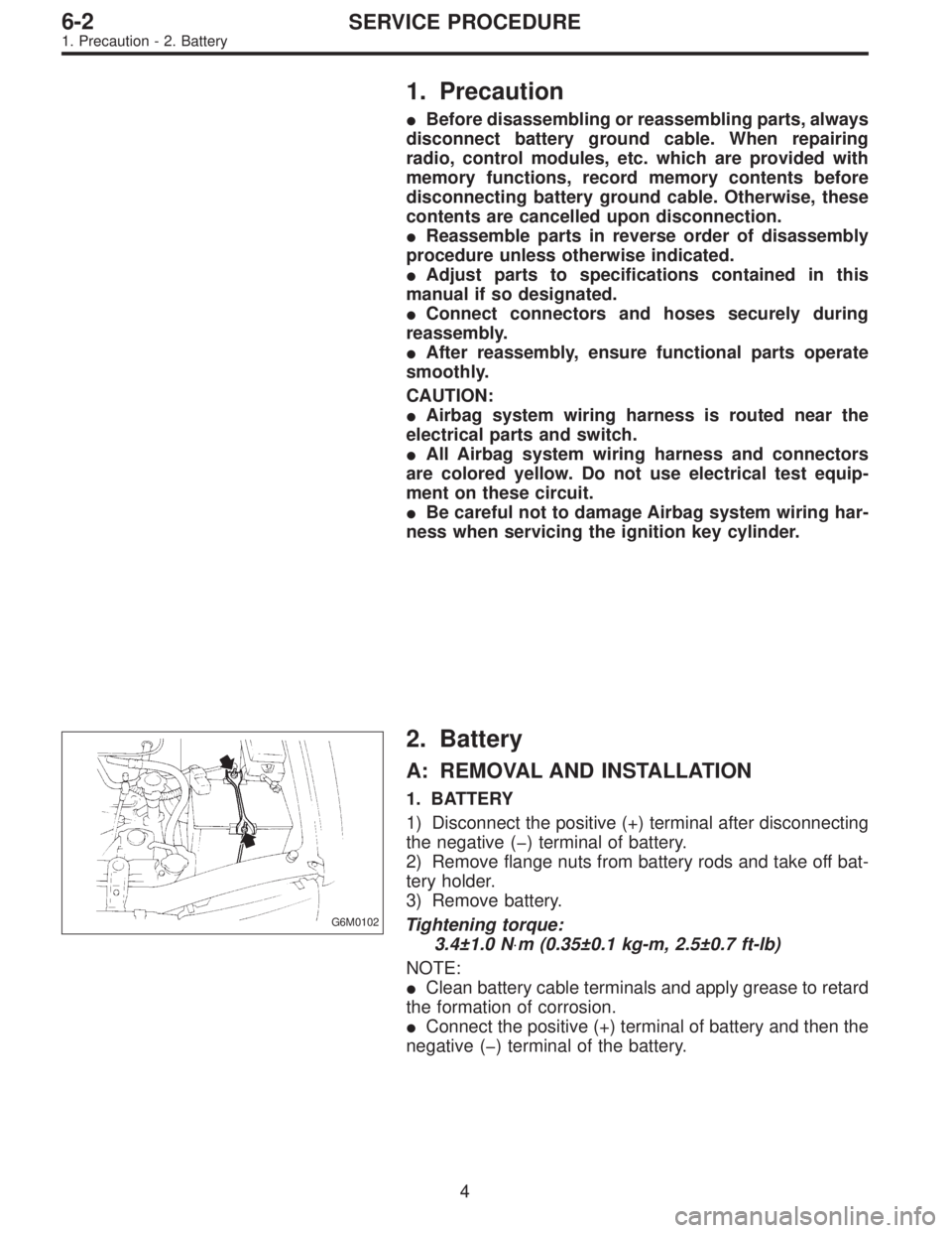
G6M0102
2. Battery
A: REMOVAL AND INSTALLATION
1. BATTERY
1) Disconnect the positive (+) terminal after disconnecting
the negative (�) terminal of battery.
2) Remove flange nuts from battery rods and take off bat-
tery holder.
3) Remove battery.
Tightening torque:
3.4±1.0 N⋅m (0.35±0.1 kg-m, 2.5±0.7 ft-lb)
NOTE:
�Clean battery cable terminals and apply grease to retard
the formation of corrosion.
�Connect the positive (+) terminal of battery and then the
negative (�) terminal of the battery.
4
6-2SERVICE PROCEDURE
1. Precaution - 2. Battery
Page 1658 of 2890

1. Precaution
�Before disassembling or reassembling parts, always
disconnect battery ground cable. When repairing
radio, control modules, etc. which are provided with
memory functions, record memory contents before
disconnecting battery ground cable. Otherwise, these
contents are cancelled upon disconnection.
�Reassemble parts in reverse order of disassembly
procedure unless otherwise indicated.
�Adjust parts to specifications contained in this
manual if so designated.
�Connect connectors and hoses securely during
reassembly.
�After reassembly, ensure functional parts operate
smoothly.
CAUTION:
�Airbag system wiring harness is routed near the
electrical parts and switch.
�All Airbag system wiring harness and connectors
are colored yellow. Do not use electrical test equip-
ment on these circuit.
�Be careful not to damage Airbag system wiring har-
ness when servicing the ignition key cylinder.
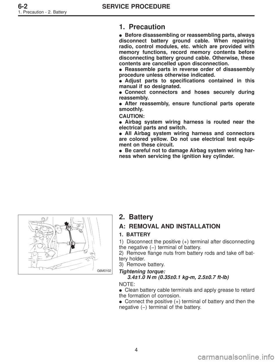
G6M0102
2. Battery
A: REMOVAL AND INSTALLATION
1. BATTERY
1) Disconnect the positive (+) terminal after disconnecting
the negative (�) terminal of battery.
2) Remove flange nuts from battery rods and take off bat-
tery holder.
3) Remove battery.
Tightening torque:
3.4±1.0 N⋅m (0.35±0.1 kg-m, 2.5±0.7 ft-lb)
NOTE:
�Clean battery cable terminals and apply grease to retard
the formation of corrosion.
�Connect the positive (+) terminal of battery and then the
negative (�) terminal of the battery.
4
6-2SERVICE PROCEDURE
1. Precaution - 2. Battery
Page 1666 of 2890
2. HEADLIGHT
1) Remove front grille and disconnect connectors from
headlight.
B6M0338
2) Remove bolts which secure headlight and remove
headlight.
Tightening torque:
6.4±0.5 N⋅m (0.65±0.05 kg-m, 4.7±0.4 ft-lb)
NOTE:
When installing the headlight, securely fit clip into locating.
B6M0339
B6M0236
3. COMBINATION SWITCH (WITHOUT AIRBAG
MODEL)
Refer to 5-5 [W7A0] as for removal of combination
switch on airbag equipped model.
1) Remove steering wheel.
2) Remove screws which secure upper column cover to
lower column cover.
3) Remove screws which secure knee protector and
remove knee protector.
CAUTION:
When installing knee protector, ensure that harness is
not caught by adjacent parts.
4) Disconnect connector from body harness and undo
holddown band.
10
6-2SERVICE PROCEDURE
4. Headlight