Page 1636 of 2890
3. Spark Plug
A: REMOVAL AND INSTALLATION
CAUTION:
All spark plugs installed on an engine, must be of the
same heat range.
Spark plug:
CHAMPION: RC10YC4
(Alternate)
NGK: BKR6E-11
NIPPONDENSO: K20PR-U11
1) Remove spark plug cords by pulling boot, not cord itself.
2) Remove spark plugs.
3) When installing spark plugs on cylinder head, use spark
plug wrench.
Tightening torque (Spark plug):
20.6±2.9 N⋅m (2.10±0.30 kg-m, 15.19±2.14 ft-lb)
CAUTION:
The above torque should be only applied to new spark
plugs without oil on their threads.
In case their threads are lubricated, the torque should
be reduced by approximately 1/3 of the specified
torque in order to avoid their over-stressing.
4) Connect spark plug cords.
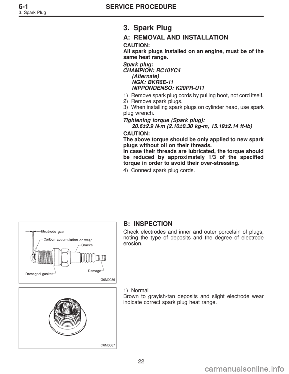
G6M0086
B: INSPECTION
Check electrodes and inner and outer porcelain of plugs,
noting the type of deposits and the degree of electrode
erosion.
G6M0087
1) Normal
Brown to grayish-tan deposits and slight electrode wear
indicate correct spark plug heat range.
22
6-1SERVICE PROCEDURE
3. Spark Plug
Page 1637 of 2890
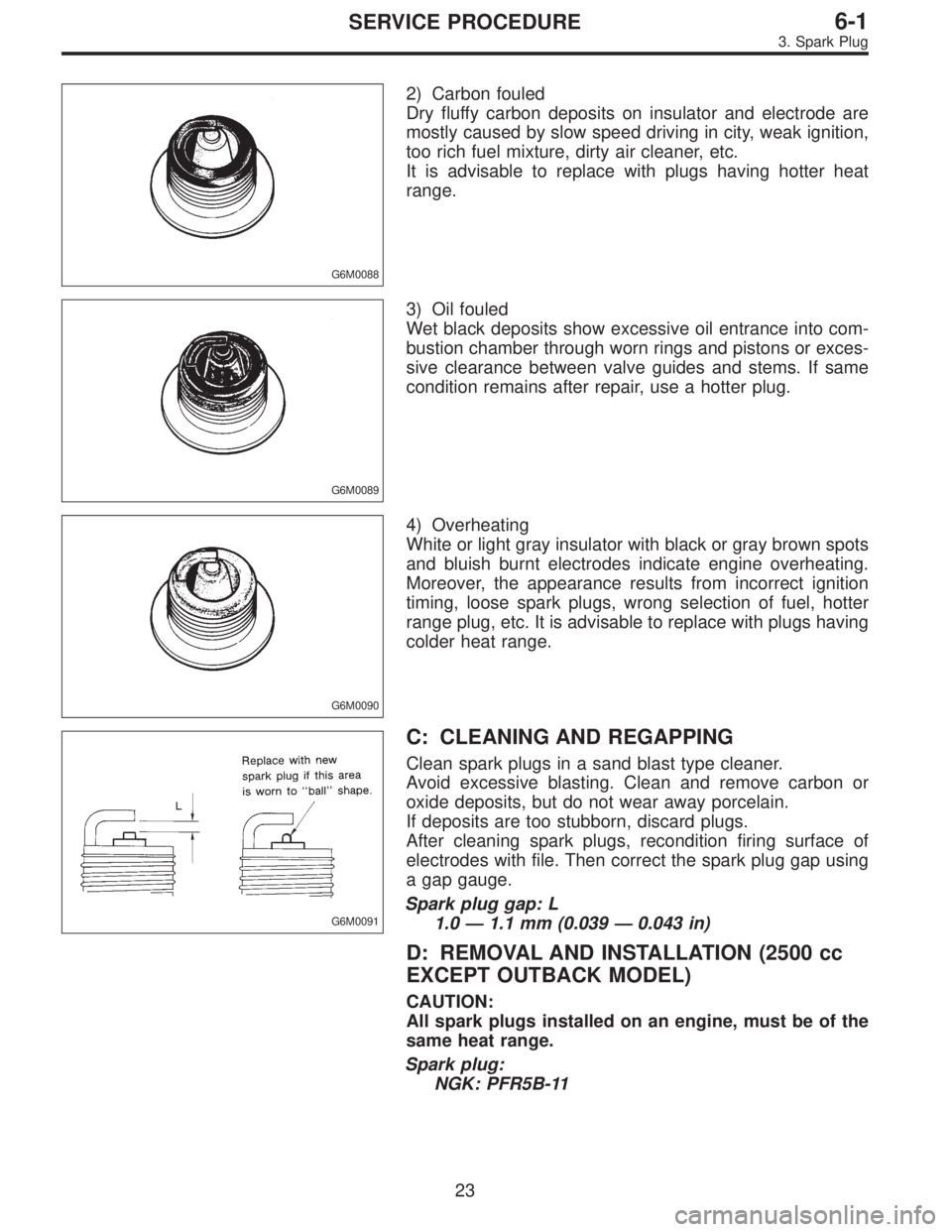
G6M0088
2) Carbon fouled
Dry fluffy carbon deposits on insulator and electrode are
mostly caused by slow speed driving in city, weak ignition,
too rich fuel mixture, dirty air cleaner, etc.
It is advisable to replace with plugs having hotter heat
range.
G6M0089
3) Oil fouled
Wet black deposits show excessive oil entrance into com-
bustion chamber through worn rings and pistons or exces-
sive clearance between valve guides and stems. If same
condition remains after repair, use a hotter plug.
G6M0090
4) Overheating
White or light gray insulator with black or gray brown spots
and bluish burnt electrodes indicate engine overheating.
Moreover, the appearance results from incorrect ignition
timing, loose spark plugs, wrong selection of fuel, hotter
range plug, etc. It is advisable to replace with plugs having
colder heat range.
G6M0091
C: CLEANING AND REGAPPING
Clean spark plugs in a sand blast type cleaner.
Avoid excessive blasting. Clean and remove carbon or
oxide deposits, but do not wear away porcelain.
If deposits are too stubborn, discard plugs.
After cleaning spark plugs, recondition firing surface of
electrodes with file. Then correct the spark plug gap using
a gap gauge.
Spark plug gap: L
1.0—1.1 mm (0.039—0.043 in)
D: REMOVAL AND INSTALLATION (2500 cc
EXCEPT OUTBACK MODEL)
CAUTION:
All spark plugs installed on an engine, must be of the
same heat range.
Spark plug:
NGK: PFR5B-11
23
6-1SERVICE PROCEDURE
3. Spark Plug
Page 1655 of 2890
1. Body Electrical
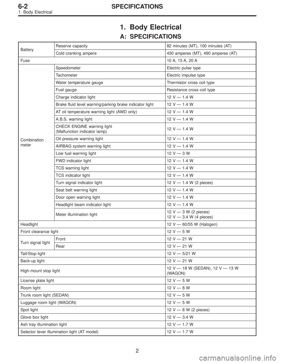
A: SPECIFICATIONS
BatteryReserve capacity 82 minutes (MT), 100 minutes (AT)
Cold cranking ampere 430 amperes (MT), 490 amperes (AT)
Fuse10 A, 15 A, 20 A
Combination
meterSpeedometer Electric pulse type
Tachometer Electric impulse type
Water temperature gauge Thermistor cross coil type
Fuel gauge Resistance cross coil type
Charge indicator light 12 V—1.4 W
Brake fluid level warning/parking brake indicator light 12 V—1.4 W
AT oil temperature warning light (AWD only) 12 V—1.4 W
A.B.S. warning light 12 V—1.4 W
CHECK ENGINE warning light
(Malfunction indicator lamp)12 V—1.4 W
Oil pressure warning light 12 V—1.4 W
AIRBAG system warning light 12 V—1.4 W
Low fuel warning light 12 V—3W
FWD indicator light 12 V—1.4 W
TCS warning light 12 V—1.4 W
TCS indicator light 12 V—1.4 W
Turn signal indicator light 12 V—1.4 W (2 pieces)
Seat belt warning light 12 V—1.4 W
Door open warning light 12 V—1.4 W
Headlight beam indicator light 12 V—1.4 W
Meter illumination light12 V—3 W (2 pieces)
12 V—3.4 W (4 pieces)
Headlight 12 V—60/55 W (Halogen)
Front clearance light 12 V—5W
Turn signal lightFront 12 V—21 W
Rear 12 V—21 W
Tail/Stop light 12 V—5/21 W
Back-up light 12 V—21 W
High-mount stop light12 V—18 W (SEDAN), 12 V—13 W
(WAGON)
License plate light 12 V—5W
Room light 12 V—8W
Trunk room light (SEDAN) 12 V—5W
Luggage room light (WAGON) 12 V—5W
Spot light 12 V—8 W (2 pieces)
Glove box light 12 V—3.4 W
Ash tray illumination light 12 V—1.7 W
Selector lever illumination light (AT model) 12 V—1.7 W
2
6-2SPECIFICATIONS
1. Body Electrical
Page 2348 of 2890
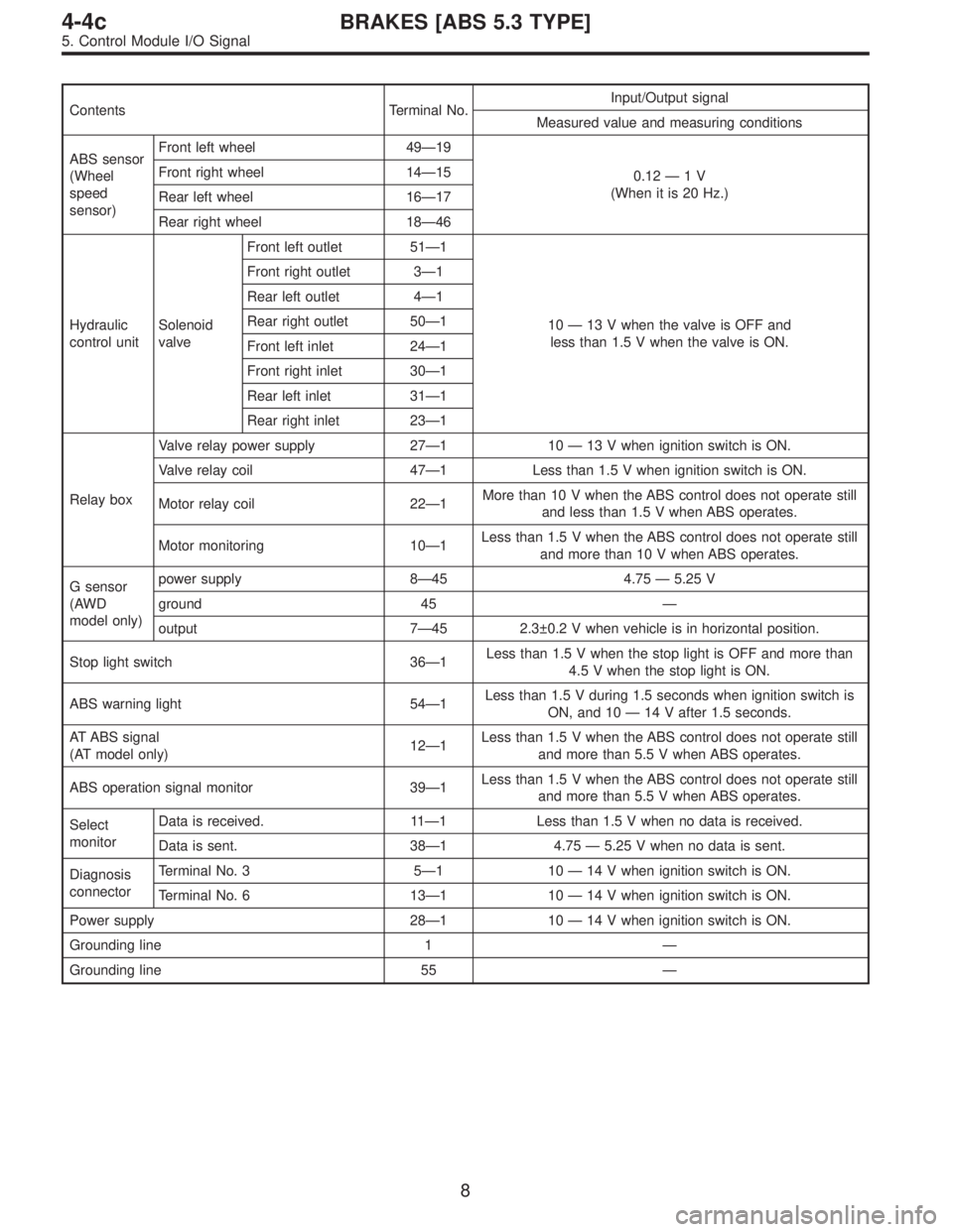
Contents Terminal No.Input/Output signal
Measured value and measuring conditions
ABS sensor
(Wheel
speed
sensor)Front left wheel 49—19
0.12—1V
(When it is 20 Hz.) Front right wheel 14—15
Rear left wheel 16—17
Rear right wheel 18—46
Hydraulic
control unitSolenoid
valveFront left outlet 51—1
10—13 V when the valve is OFF and
less than 1.5 V when the valve is ON. Front right outlet 3—1
Rear left outlet 4—1
Rear right outlet 50—1
Front left inlet 24—1
Front right inlet 30—1
Rear left inlet 31—1
Rear right inlet 23—1
Relay boxValve relay power supply 27—110—13 V when ignition switch is ON.
Valve relay coil 47—1 Less than 1.5 V when ignition switch is ON.
Motor relay coil 22—1More than 10 V when the ABS control does not operate still
and less than 1.5 V when ABS operates.
Motor monitoring 10—1Less than 1.5 V when the ABS control does not operate still
and more than 10 V when ABS operates.
G sensor
(AWD
model only)power supply 8—45 4.75—5.25 V
ground 45—
output 7—45 2.3±0.2 V when vehicle is in horizontal position.
Stop light switch 36—1Less than 1.5 V when the stop light is OFF and more than
4.5 V when the stop light is ON.
ABS warning light 54—1Less than 1.5 V during 1.5 seconds when ignition switch is
ON, and 10—14 V after 1.5 seconds.
AT ABS signal
(AT model only)12—1Less than 1.5 V when the ABS control does not operate still
and more than 5.5 V when ABS operates.
ABS operation signal monitor 39—1Less than 1.5 V when the ABS control does not operate still
and more than 5.5 V when ABS operates.
Select
monitorData is received. 11—1 Less than 1.5 V when no data is received.
Data is sent. 38—1 4.75—5.25 V when no data is sent.
Diagnosis
connectorTerminal No. 3 5—110—14 V when ignition switch is ON.
Terminal No. 6 13—110—14 V when ignition switch is ON.
Power supply 28—110—14 V when ignition switch is ON.
Grounding line 1—
Grounding line 55—
8
4-4cBRAKES [ABS 5.3 TYPE]
5. Control Module I/O Signal
Page 2613 of 2890
B: CHECKING THE HYDRAULIC UNIT
OPERATION
1) Do ABS sequence control patterns take place in correct
order?
If not, check wiring and piping for incorrect connections.
2) Are oil pressure or braking force variations within speci-
fications?
If not, check master cylinder, brake piping, hydraulic unit,
proportioning valve and wheel cylinder for improper opera-
tion.
3) Does pedal hardness change before and after ABS
sequence control?
If so, bleed air from brake line.
273
4-4cBRAKES [ABS 5.3 TYPE]
11. General Diagnostics Table
Page 2878 of 2890
How to use this manual
�This Service Manual is divided into four volumes by section so that it can be used with ease at work. Refer to
the Table of Contents, select and use the necessary section.
�GENERAL INFORMATION SECTION
�REPAIR SECTION
�TROUBLESHOOTING SECTION
�WIRING DIAGRAM SECTION
�Each chapter in the manual is basically made of the following four types of areas.
S SPECIFICATIONS AND SERVICE DATA
C COMPONENT PARTS
W SERVICE PROCEDURE
(X SERVICE PROCEDURE)
(Y SERVICE PROCEDURE)
K DIAGNOSTICS
�The description of each area is provided with four types of titles different in size as shown below. The Title No.
or Symbol prefixes each title in order that the construction of the article and the flow of explanation can be eas-
ily understood.
[Example of each title]
�Area title: W SERVICE PROCEDURE (one of the four types of areas)
�Large title (Heading): 1. Oil Pump (to denote the main item of explanation)
�Medium title (Section): A: REMOVAL (to denote the type of work in principle)
�Small title (Sub-section): 1. INNER ROTATOR (to denote a derivative item of explanation)
3