Page 1921 of 2890
OBD0145A
10G1CONNECT SUBARU SELECT MONITOR
OR THE OBD-II GENERAL SCAN TOOL,
AND READ DATA.
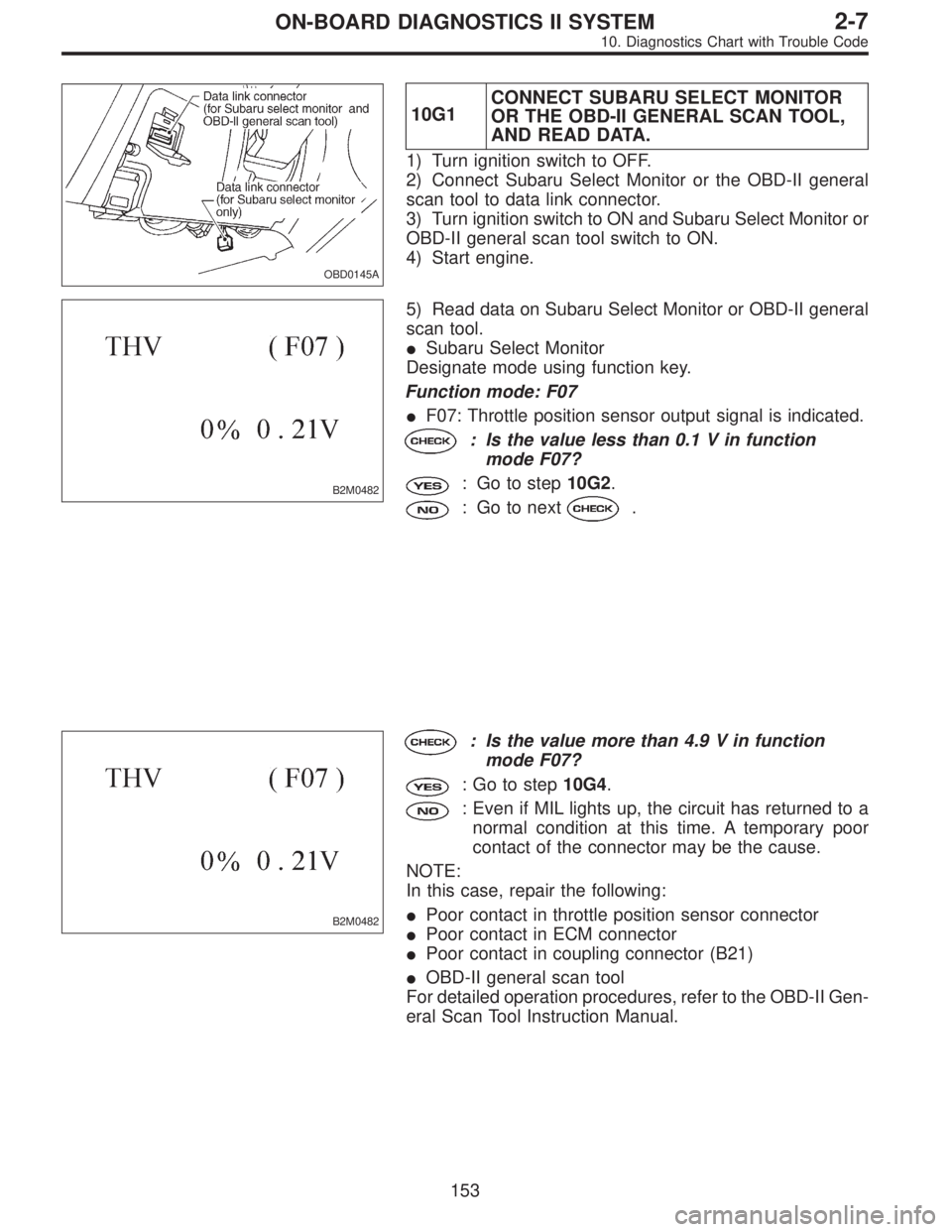
1) Turn ignition switch to OFF.
2) Connect Subaru Select Monitor or the OBD-II general
scan tool to data link connector.
3) Turn ignition switch to ON and Subaru Select Monitor or
OBD-II general scan tool switch to ON.
4) Start engine.
B2M0482
5) Read data on Subaru Select Monitor or OBD-II general
scan tool.
�Subaru Select Monitor
Designate mode using function key.
Function mode: F07
�F07: Throttle position sensor output signal is indicated.
: Is the value less than 0.1 V in function
mode F07?
: Go to step10G2.
: Go to next.
B2M0482
: Is the value more than 4.9 V in function
mode F07?
: Go to step10G4.
: Even if MIL lights up, the circuit has returned to a
normal condition at this time. A temporary poor
contact of the connector may be the cause.
NOTE:
In this case, repair the following:
�Poor contact in throttle position sensor connector
�Poor contact in ECM connector
�Poor contact in coupling connector (B21)
�OBD-II general scan tool
For detailed operation procedures, refer to the OBD-II Gen-
eral Scan Tool Instruction Manual.
153
2-7ON-BOARD DIAGNOSTICS II SYSTEM
10. Diagnostics Chart with Trouble Code
Page 1982 of 2890
B2M0244A
10AA3
CHECK KNOCK SENSOR.
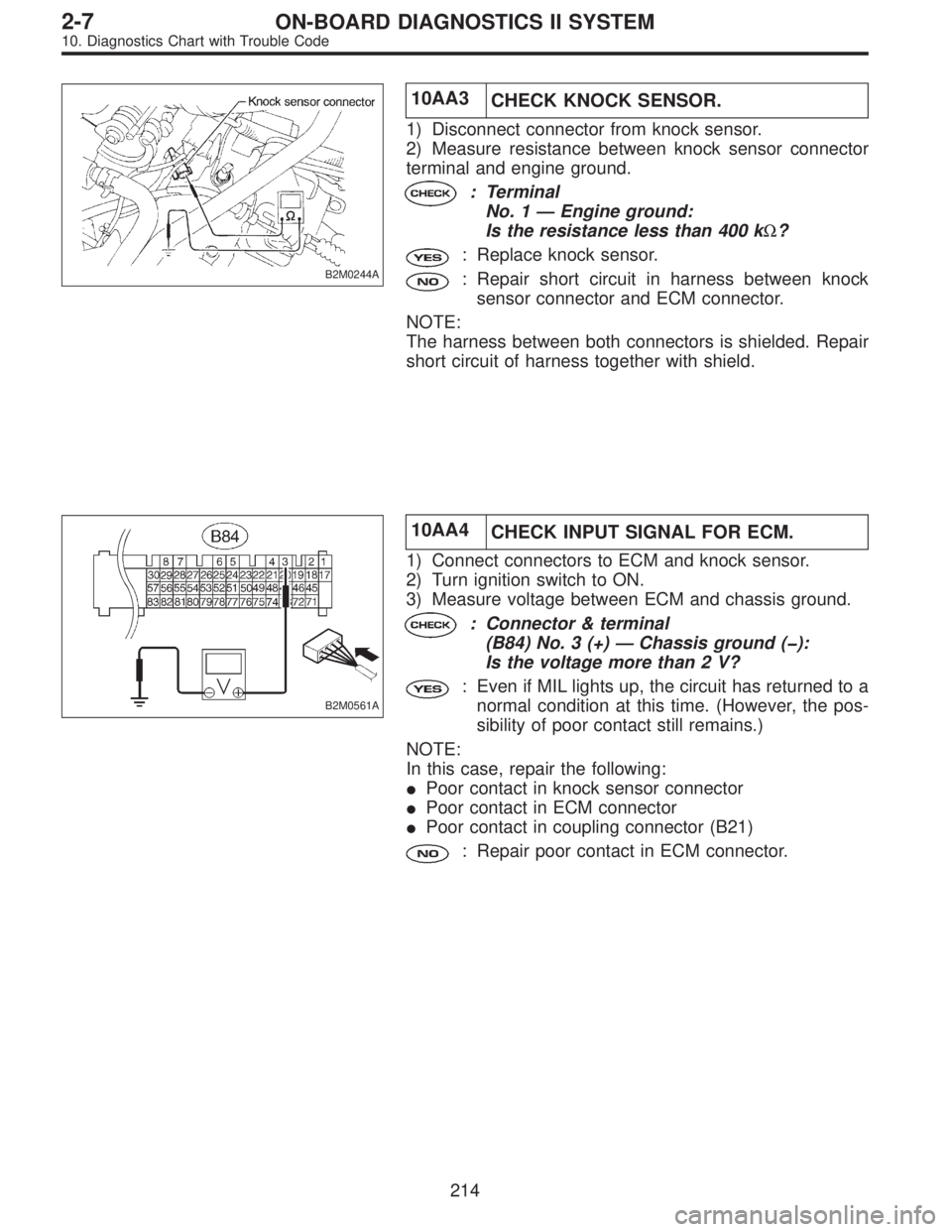
1) Disconnect connector from knock sensor.
2) Measure resistance between knock sensor connector
terminal and engine ground.
: Terminal
No. 1—Engine ground:
Is the resistance less than 400 kΩ?
: Replace knock sensor.
: Repair short circuit in harness between knock
sensor connector and ECM connector.
NOTE:
The harness between both connectors is shielded. Repair
short circuit of harness together with shield.
B2M0561A
10AA4
CHECK INPUT SIGNAL FOR ECM.
1) Connect connectors to ECM and knock sensor.
2) Turn ignition switch to ON.
3) Measure voltage between ECM and chassis ground.
: Connector & terminal
(B84) No. 3 (+)—Chassis ground (�):
Is the voltage more than 2 V?
: Even if MIL lights up, the circuit has returned to a
normal condition at this time. (However, the pos-
sibility of poor contact still remains.)
NOTE:
In this case, repair the following:
�Poor contact in knock sensor connector
�Poor contact in ECM connector
�Poor contact in coupling connector (B21)
: Repair poor contact in ECM connector.
214
2-7ON-BOARD DIAGNOSTICS II SYSTEM
10. Diagnostics Chart with Trouble Code
Page 2111 of 2890
H2M1327
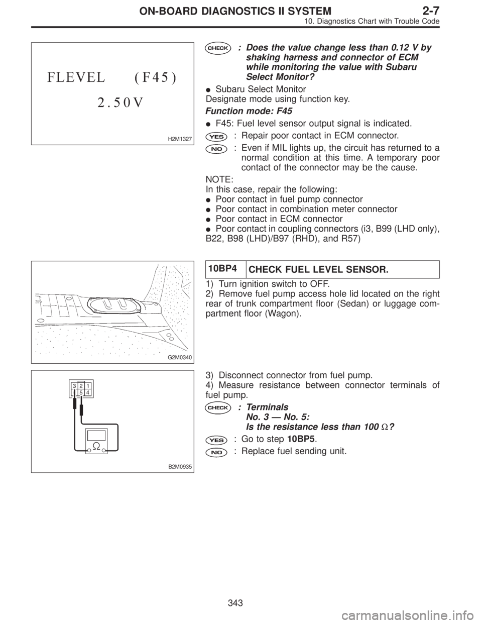
: Does the value change less than 0.12 V by
shaking harness and connector of ECM
while monitoring the value with Subaru
Select Monitor?
�Subaru Select Monitor
Designate mode using function key.
Function mode: F45
�F45: Fuel level sensor output signal is indicated.
: Repair poor contact in ECM connector.
: Even if MIL lights up, the circuit has returned to a
normal condition at this time. A temporary poor
contact of the connector may be the cause.
NOTE:
In this case, repair the following:
�Poor contact in fuel pump connector
�Poor contact in combination meter connector
�Poor contact in ECM connector
�Poor contact in coupling connectors (i3, B99 (LHD only),
B22, B98 (LHD)/B97 (RHD), and R57)
G2M0340
10BP4
CHECK FUEL LEVEL SENSOR.
1) Turn ignition switch to OFF.
2) Remove fuel pump access hole lid located on the right
rear of trunk compartment floor (Sedan) or luggage com-
partment floor (Wagon).
B2M0935
3) Disconnect connector from fuel pump.
4) Measure resistance between connector terminals of
fuel pump.
: Terminals
No. 3—No. 5:
Is the resistance less than 100Ω?
: Go to step10BP5.
: Replace fuel sending unit.
343
2-7ON-BOARD DIAGNOSTICS II SYSTEM
10. Diagnostics Chart with Trouble Code
Page 2204 of 2890
DISPLAY
LED No. Signal name Symbol
1 FWD switch FF
2 Kick-down switch KD
3——
4——
5 Brake BR
6 ABS switch AB
7 Cruise control set CR
8 Power switch PW
9——
10——
FF KD—— ——BR
AB CR PW—— ——
1
2345
678910
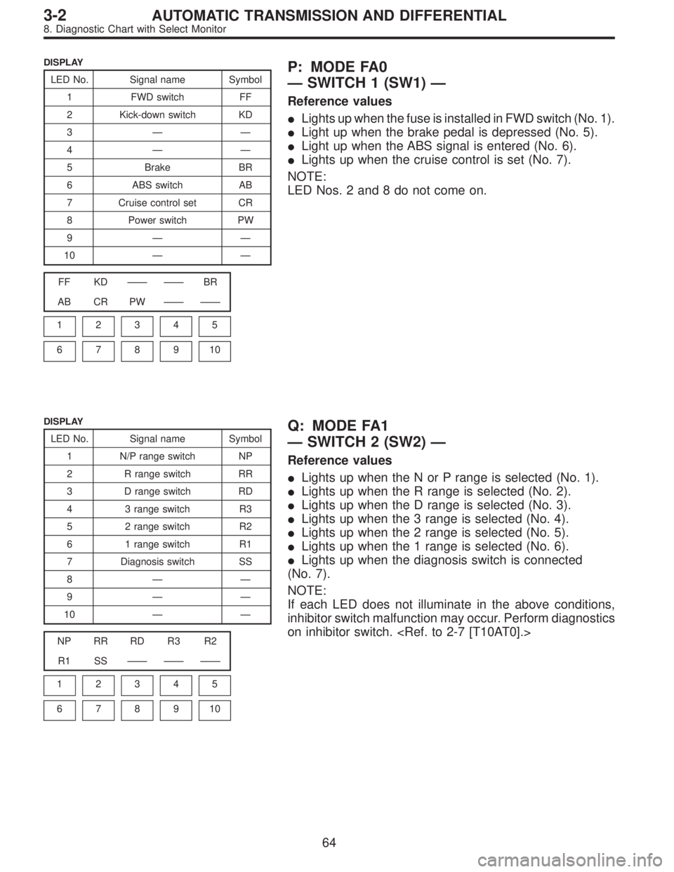
P: MODE FA0
—SWITCH 1 (SW1)—
Reference values
�Lights up when the fuse is installed in FWD switch (No. 1).
�Light up when the brake pedal is depressed (No. 5).
�Light up when the ABS signal is entered (No. 6).
�Lights up when the cruise control is set (No. 7).
NOTE:
LED Nos. 2 and 8 do not come on.
DISPLAY
LED No. Signal name Symbol
1 N/P range switch NP
2 R range switch RR
3 D range switch RD
4 3 range switch R3
5 2 range switch R2
6 1 range switch R1
7 Diagnosis switch SS
8——
9——
10——
NP RR RD R3 R2
R1 SS—— —— ——
1
2345
678910
Q: MODE FA1
—SWITCH 2 (SW2)—
Reference values
�Lights up when the N or P range is selected (No. 1).
�Lights up when the R range is selected (No. 2).
�Lights up when the D range is selected (No. 3).
�Lights up when the 3 range is selected (No. 4).
�Lights up when the 2 range is selected (No. 5).
�Lights up when the 1 range is selected (No. 6).
�Lights up when the diagnosis switch is connected
(No. 7).
NOTE:
If each LED does not illuminate in the above conditions,
inhibitor switch malfunction may occur. Perform diagnostics
on inhibitor switch.
64
3-2AUTOMATIC TRANSMISSION AND DIFFERENTIAL
8. Diagnostic Chart with Select Monitor
Page 2225 of 2890
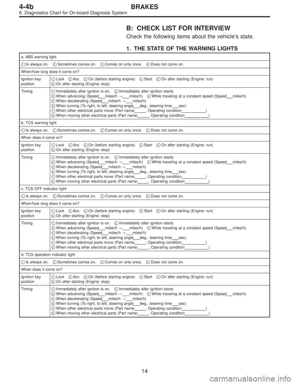
B: CHECK LIST FOR INTERVIEW
Check the following items about the vehicle’s state.
1. THE STATE OF THE WARNING LIGHTS
a. ABS warning light
�
1Is always on.�2Sometimes comes on.�3Comes on only once.�4Does not come on.
When/how long does it come on?
Ignition key
position�
1Lock�2Acc�3On (before starting engine)�4Start�5On after starting (Engine: run)
�6On after starting (Engine: stop)
Timing�
1Immediately after ignition is on.�2Immediately after ignition starts.
�3When advancing (Speedmiles/h,miles/h)�4While traveling at a constant speed (Speedmiles/h)
�5When decelerating (Speedmiles/h,miles/h)
�6When turning (To right, to left, steering angledeg., steering timesec)
�7When other electrical parts move (Part name:, Operating condition)
�8When moving other electrical parts (Part name:, Operating condition)
b. TCS warning light
�
1Is always on.�2Sometimes comes on.�3Comes on only once.�4Does not come on.
When does it come on?
Ignition key
position�
1Lock�2Acc�3On (before starting engine)�4Start�5On after starting (Engine: run)
�6On after starting (Engine: stop)
Timing�
1Immediately after ignition is on.�2Immediately after ignition starts.
�3When advancing (Speedmiles/h,miles/h)�4While traveling at a constant speed (Speedmiles/h)
�5When decelerating (Speedmiles/h,miles/h)
�6When turning (To right, to left, steering angledeg., steering timesec)
�7When other electrical parts move (Part name:, Operating condition)
�8When moving other electrical parts (Part name:, Operating condition)
c. TCS OFF indicator light
�
1Is always on.�2Sometimes comes on.�3Comes on only once.�4Does not come on.
When/how long does it come on?
Ignition key
position�
1Lock�2Acc�3On (before starting engine)�4Start�5On after starting (Engine: run)
�6On after starting (Engine: stop)
Timing�
1Immediately after ignition is on.�2Immediately after ignition starts.
�3When advancing (Speedmiles/h,miles/h)�4While traveling at a constant speed (Speedmiles/h)
�5When decelerating (Speedmiles/h,miles/h)
�6When turning (To right, to left, steering angledeg., steering timesec)
�7When other electrical parts move (Part name:, Operating condition)
�8When moving other electrical parts (Part name:, Operating condition)
d. TCS operation indicator light
�
1Is always on.�2Sometimes comes on.�3Comes on only once.�4Does not come on.
When does it come on?
Ignition key
position�
1Lock�2Acc�3On (before starting engine)�4Start�5On after starting (Engine: run)
�6On after starting (Engine: stop)
Timing�
1Immediately after ignition is on.�2Immediately after ignition starts.
�3When advancing (Speedmiles/h,miles/h)�4While traveling at a constant speed (Speedmiles/h)
�5When decelerating (Speedmiles/h,miles/h)
�6When turning (To right, to left, steering angledeg., steering timesec)
�7When other electrical parts move (Part name:, Operating condition)
�8When moving other electrical parts (Part name:, Operating condition)
14
4-4bBRAKES
6. Diagnostics Chart for On-board Diagnosis System
Page 2231 of 2890
B: ABS AND TCS WARNING LIGHT DO NOT
GO OFF.
—TCS OFF AND TCS OPERATING
INDICATOR LIGHTS COME ON AND GO OFF
PROPERLY WHEN STARTING THE ENGINE,
WHILE ABS WARNING AND TCS WARNING
LIGHTS KEEP ON.—
1. Check brake fluid level.
OK
�Not OK
Add to brake fluid.
2. Check brake fluid level sensor.
OK
�Not OK
Replace master cylinder.
3. Check harness connector between ABS/TCS
control module and alternator.
OK
�Not OK
Replace harness connector.
Replace ABS/TCS control module.
B4M0389
�
�
�
20
4-4bBRAKES
7. Diagnostics Chart for Warning Light Circuit Failure
Page 2233 of 2890
C: TCS WARNING LIGHT AND TCS
INDICATOR OFF AND TCS OPERATING
INDICATOR LIGHTS COME ON AND GO OFF
PROPERLY, WHILE ABS WARNING LIGHT
DOES NOT GO OFF.
—TCS WARNING LIGHT AND TCS OFF
INDICATOR AND TCS OPERATING
INDICATOR LIGHTS COME ON AND GO OFF
PROPERLY WHEN STARTING THE ENGINE,
WHILE ABS WARNING LIGHT DOES NOT GO
OFF.—
1. Check harness connector between ABS/TCS
control module and ABS warning light.�Repair harness connector.
Replace ABS/TCS control module.
B4M0392
�
22
4-4bBRAKES
7. Diagnostics Chart for Warning Light Circuit Failure
Page 2237 of 2890
E: TCS OFF INDICATOR LIGHT DOES NOT
GO OFF.
—ABS WARNING, TCS WARNING AND TCS
OPERATING INDICATOR LIGHTS COME ON
AND GO OFF PROPERLY WHEN STARTING
THE ENGINE, BUT TCS OFF INDICATOR
DOES NOT GO OFF FOR MORE THAN 30
SECONDS AFTER ENGINE RUNNING.—
Does malfunction indicator lamp (Check engine
lamp) come on?
No
�Ye s
Conduct OBD II diagnosis.
1. Check harness connector between ABS/TCS
control module and TCS OFF indicator light.
OK
�Not OK
Repair harness/connector.
Replace ABS/TCS control module.
B4M0396
�
�
26
4-4bBRAKES
7. Diagnostics Chart for Warning Light Circuit Failure