Page 167 of 2890
5-5b
[TSPO]
SUPPLEMENTAL
RESTRAINT
SYSTEM
(ELECTRIC
SENSOR
TYPE)
5
.
DiagnosticsChart
with
Trouble
Code
P
:
WARNING
LIGHT
INDICATES
TROUBLE
CODE,
THEN
NORMAL
CODE
.
-
FLASHING
TROUBLE
CODE
.
-
DIAGNOSIS
:
Airbagsystem
component
parts
are
faulty
.
1
.
Airbag
component
parts
appearance
inspection
1
2
.
Airbag
component
parts
vibration
inspection
1
3
.
Showering
Inspection
to
body
CAUTION
:
Beforeperforming
diagnostics
on
airbag
system,
turn
ignition
switch
"OFF",
disconnect
battery
ground
cable,
and
thenwait
at
least
20
seconds
.
38
Page 170 of 2890
![SUBARU LEGACY 1996 Service Repair Manual
SUPPLEMENTAL
RESTRAINT
SYSTEM
(ELECTRIC
SENSOR
TYPE)
[T5(a1]
5-5b
5
.
Diagnostics
Chart
with
Trouble
Code
Q
:
WARNING
LIGHTINDICATES
TROUBLE
CODE,
THEN
NORMAL
CODE
.
-
FLASHING
NORMAL
CODE
.
-
D SUBARU LEGACY 1996 Service Repair Manual
SUPPLEMENTAL
RESTRAINT
SYSTEM
(ELECTRIC
SENSOR
TYPE)
[T5(a1]
5-5b
5
.
Diagnostics
Chart
with
Trouble
Code
Q
:
WARNING
LIGHTINDICATES
TROUBLE
CODE,
THEN
NORMAL
CODE
.
-
FLASHING
NORMAL
CODE
.
-
D](/manual-img/17/57433/w960_57433-169.png)
SUPPLEMENTAL
RESTRAINT
SYSTEM
(ELECTRIC
SENSOR
TYPE)
[T5(a1]
5-5b
5
.
Diagnostics
Chart
with
Trouble
Code
Q
:
WARNING
LIGHTINDICATES
TROUBLE
CODE,
THEN
NORMAL
CODE
.
-
FLASHING
NORMAL
CODE
.
-
DIAGNOSIS
:
"
Airbag
connector
is
faulty
.
"
Fuse
No
.
16
is
blown
.
"
Airbag
.
main
harness
is
faulty
.
"
Airbag
control
module
is
faulty
.
"
Body
harness
is
faulty
.
1
1
.
Airbag
connector
appearance
inspection
1
2
.
Atrbag
connector
vibration
inspection
3
.
Showering
inspection
to
body
4
.
Fuse
No
.
16,
airbag
main
harness,
airbag
control
module,
body
harness
appearance
inspection
5
.
Fuse
No
.
16,
airbag
main
harness,
body
harness
vibration
inspection
1
6
.
Showering
inspectionto
body
1
7
.
Warning
light
illumination
check
CAUTION
:
Before
performing
diagnostics
on
airbag
system,
turn
ignition
switch
"OFF",
disconnect
battery
ground
cable,
and
then
wait
at
least
20
seconds
.
1
.
AIRBAG
CONNECTOR
APPEARANCE
INSPECTION
Conduct
appearance
inspection
on
airbag
connectors
(AB2)
through
(AB8)
.
<
Ref
.
to
5-5
[T100]
.*2
>
CHECK
:
Is
thereanything
unusualabout
the
appear-
ance
of
connectors(AB2)
through
(AB8)?
,rES
:
Replace
faulty
airbag
component
parts
.
No
:
Go
to
step
2
.
NOTE
:
Check
terminals,
case
and
wiring
harnesses
for
damage
.
41
Page 173 of 2890
![SUBARU LEGACY 1996 Service Repair Manual 6-3
[D601]
WIRING
DIAGRAM
6
.
Wiring
Diagram
6
.
Wiring
Diagram
Batterycurrent
1
.
POWER
SUPPLY
ROUTING
Current
fromignition
switch
IG
terminal
---
Current
fromignition
switch
ACC
terminal
----- SUBARU LEGACY 1996 Service Repair Manual 6-3
[D601]
WIRING
DIAGRAM
6
.
Wiring
Diagram
6
.
Wiring
Diagram
Batterycurrent
1
.
POWER
SUPPLY
ROUTING
Current
fromignition
switch
IG
terminal
---
Current
fromignition
switch
ACC
terminal
-----](/manual-img/17/57433/w960_57433-172.png)
6-3
[D601]
WIRING
DIAGRAM
6
.
Wiring
Diagram
6
.
Wiring
Diagram
Batterycurrent
1
.
POWER
SUPPLY
ROUTING
Current
fromignition
switch
IG
terminal
---
Current
fromignition
switch
ACC
terminal
-------
Other
currents
Mainfuse
box
(M/B)
g27
SBF-5
45A
~
L
SBF-4
45A
,
BY
r-,
coc_
:
/CA
1
Do
BF-1
30A
BF-2
30A
N
m
m
M/B
FUSE/RELAY
LOCATION
826
-
MB-1
2
Rw
M
B-2
1
MB-3
R
-
MB-4
(
:8
~V
:
9)
,
R
F35
Headlight
No
.
22
15A
5
W
relay
LHNo
.
23
20A
Br
6
°
No
.
24
15A
RL
-----
---------
------0'
~-P--
1
---------°^----
MB-6
7
LB
7
No
.
26
15A
BY
°
~
~
_
No
.
25
15A
3
--°--°
BR
MB-8
.J
4
LR
2
MB-9
Headlight
relay
RH
F38
r~W
WC
relay
holder
mmllmm
O
~
SBFSBF
~~~
~
Head
i~25
N0
'
24
Headlight
4A
No,
relay
RH
~
SBF
~
38fSBf
N0
.
b
F/B
a
N0
.
--
2
:
0
N0
.f
o
N
.
176
N
RU7
.
R-DEF
N0
.
7
N0
.
N
.
3
0N
.
It
.4
~~
P
I
.7
LEI]
o
O
N0
.
19N0
.
12N0
.
~y~~~,~~~
ILLUrtI
.
O
N0.21
N0
.
14
N0
.7
MAIN
FAN
,
D
2
IF--
F26
F38
(B
I
ec
k)
2
B27
123
--'----
ALT-1
B26
(B
I
ac
k)
F26
(Grey)
12
F35
(B
I
ec
k)
1234
5678
BURO1-01A
Page 203 of 2890
![SUBARU LEGACY 1996 Service Repair Manual 3-2
[raB11]
AUTOMATIC
TRANSMISSION
AND
DIFFERENTIAL
8
.
Diagnostic
Chart
withSelect
Monitor
8
.
Diagnostic
Chart
with
Select
Monitor
B
:
LIST
OF
OUTPUT
MODES
1
.
FUNCTION
MODE
Mode
Contents
Abbr
SUBARU LEGACY 1996 Service Repair Manual 3-2
[raB11]
AUTOMATIC
TRANSMISSION
AND
DIFFERENTIAL
8
.
Diagnostic
Chart
withSelect
Monitor
8
.
Diagnostic
Chart
with
Select
Monitor
B
:
LIST
OF
OUTPUT
MODES
1
.
FUNCTION
MODE
Mode
Contents
Abbr](/manual-img/17/57433/w960_57433-202.png)
3-2
[raB11]
AUTOMATIC
TRANSMISSION
AND
DIFFERENTIAL
8
.
Diagnostic
Chart
withSelect
Monitor
8
.
Diagnostic
Chart
with
Select
Monitor
B
:
LIST
OF
OUTPUT
MODES
1
.
FUNCTION
MODE
Mode
Contents
Abbr
.
Unit
Contents
of
display
Page
F00
Mode
display
--
AT
or
EGI
mode
(when
monitor
is
connected
.)
-
F01Battery
voltage
VBV
Battery
voltage
applied
to
control
unit
.
-
F02
Vehicle
speed
sensor
1
VSPi
m/h
Vehicle
speed
(miles/h)
sent
from
vehicle
speed
sensor
1
.
-
F03
Vehicle
speed
sensor
1
VSP1
km/h
Vehicle
speed
(km/h)sent
from
vehicle
speed
sensor
1
.
-
F04
Vehicle
speed
sensor
2
VSP2
m/h
Vehicle
speed
(miles/h)
sentfrom
vehicle
speed
sensor
2
.
-
F05
Vehicle
speed
sensor
2
VSP2
km/h
Vehicle
speed
(km/h)
sent
from
vehicle
speed
sensor
2
.
-
F06
Engine
speed
EREV
rpm
Engine
speed
sent
from
ECM
.
-
F07
ATF
temperature
sensor
ATFT
°F
ATF
temperature
(°F)
sent
from
ATF
temperature
sensor
.
-
F08
ATF
temperature
sensor
ATFT
°C
ATF
temperature
(°C)
sent
from
ATF
temperature
sensor
.
-
F09
Throttleposition
sensor
THV
V
Voltage
sent
from
throttle
position
sensor
.
15
F10
Gear
position
GEAR
-
Transmissiongear
position
-
F11Line
pressure
duty
PLDTY
%
Duty
ratio
flowing
through
duty
solenoid
A
.
16
F12
Lock-up
duty
LUDTY
%
Duty
ratio
flowing
through
duty
solenoid
B
.
17
F13
AWD
duty
4WDTY
%
Duty
ratio
flowing
through
duty
solenoid
C
.
18
F14
Throttle
position
sensor
power
supply
THVCC
VPower
supply
voltage
to
throttle
position
sensor
19
F15
Mass
air
flowsignal
l
AFM
V
Output
voltage
from
air
flow
sensor
19
14
Page 218 of 2890

ON-BOARD
DIAGNOSTICS
II
SYSTEM
[Tsisl
2-7
8
.
Diagnostics
for
Engine
Starting
Failure
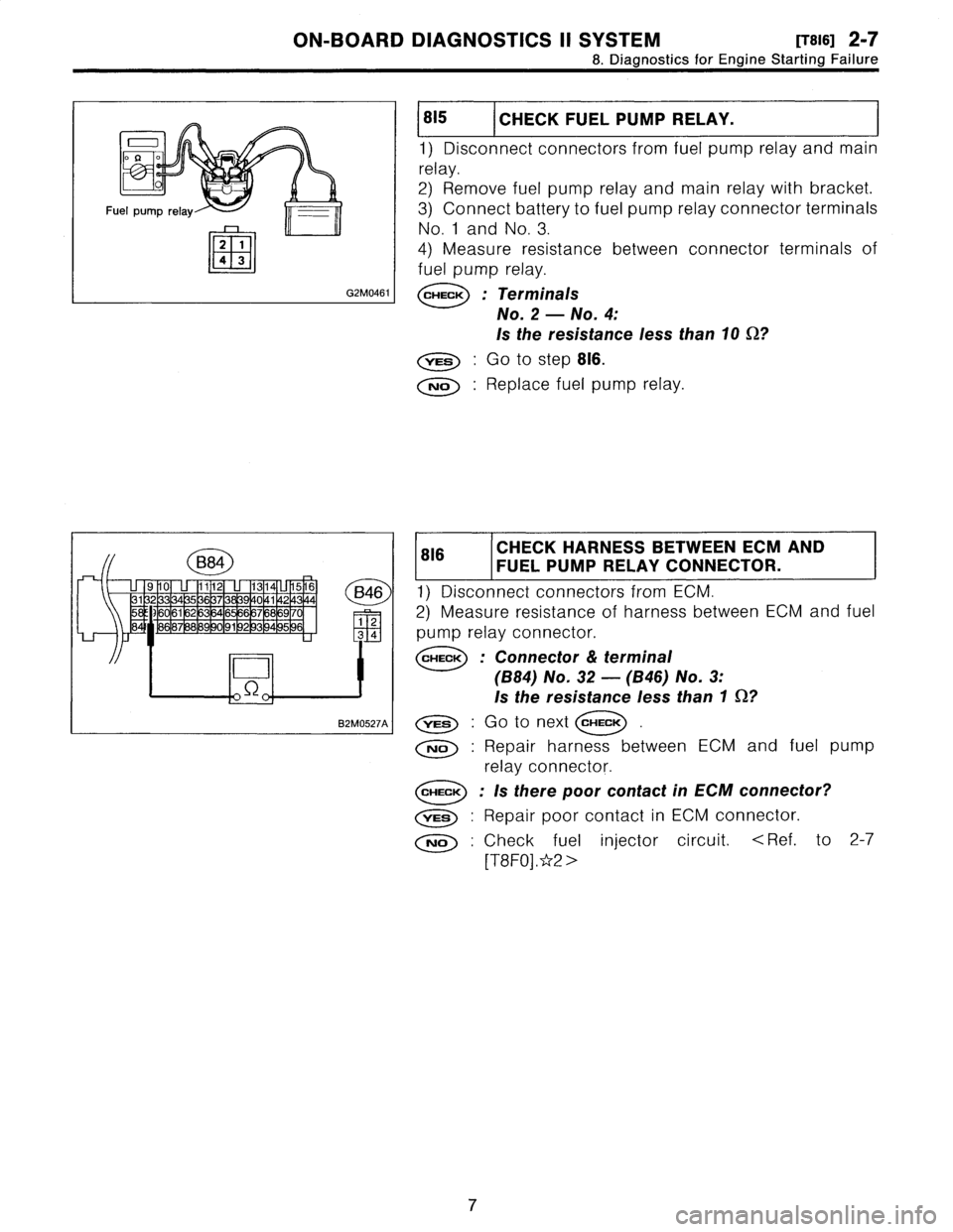
815
1
CHECK
FUEL
PUMP
RELAY
.
1)
Disconnectconnectors
from
fuel
pump
relay
and
main
relay
.
2)
Remove
fuel
pump
relay
and
main
relay
with
bracket
.
3)
Connect
battery
to
fuel
pump
relay
connector
terminals
No
.
1
and
No
.
3
.
4)
Measure
resistance
between
connector
terminals
of
fuel
pump
relay
.
CHECK
;
Terminals
No
.
2
-
No
.
4
:
Is
the
resistance
less
than10
92?
YES
:
Go
tostep
816
.
No
:
Replace
fuel
pump
relay
.
816
CHECK
HARNESS
BETWEEN
ECM
FUEL
PUMP
RELAY
CONNECTOR
.
AND
1)
Disconnectconnectors
from
ECM
.
2)
Measure
resistanceof
harness
between
ECM
and
fuel
pump
relay
connector
.
CHECK
:
Connector
&
terminal
(B84)
No
.
32
-
(B46)
No
.
3
:
Is
the
resistance
less
than
1
0?
YES
.
Go
to
next
CHECK
No
:
Repair
harness
between
ECM
and
fuel
pump
relay
connector
.
CHECK
:
Is
there
poor
contact
in
ECM
connector?
vES
:
Repair
poor
contact
in
ECM
connector
.
No
:
Check
fuel
injector
circuit
.
<
Ref
.
to
2-7
[T8F0]
.*2
>
7
Page 290 of 2890
B2M0425A
7. EGR Solenoid Valve
A: REMOVAL AND INSTALLATION
1) Remove bolt which installs EGR solenoid valve onto
intake manifold.
2) Disconnect hoses and connector from EGR solenoid
valve.
NOTE:
This figure shows the rear side of intake manifold.
3) Installation is in the reverse order of removal.
Tightening torque:
19±5 N⋅m (1.9±0.5 kg-m, 13.7±3.6 ft-lb)
G6M0095
8. Fuel Temperature Sensor (2200 cc
AWD Model)
A: REMOVAL
1) Disconnect battery ground cable.
B2M0954A
2) Release fuel pressure.
3) Disconnect fuel delivery hose�
1, return hose�2and jet
pump hose�
3.
B2M0955
4) Remove nuts which install fuel pump assembly onto
fuel tank.
9
2-1SERVICE PROCEDURE
7. EGR Solenoid Valve - 8. Fuel Temperature Sensor (2200 cc AWD Model)
Page 291 of 2890
B2M0425A
7. EGR Solenoid Valve
A: REMOVAL AND INSTALLATION
1) Remove bolt which installs EGR solenoid valve onto
intake manifold.
2) Disconnect hoses and connector from EGR solenoid
valve.
NOTE:
This figure shows the rear side of intake manifold.
3) Installation is in the reverse order of removal.
Tightening torque:
19±5 N⋅m (1.9±0.5 kg-m, 13.7±3.6 ft-lb)
G6M0095
8. Fuel Temperature Sensor (2200 cc
AWD Model)
A: REMOVAL
1) Disconnect battery ground cable.
B2M0954A
2) Release fuel pressure.
3) Disconnect fuel delivery hose�
1, return hose�2and jet
pump hose�
3.
B2M0955
4) Remove nuts which install fuel pump assembly onto
fuel tank.
9
2-1SERVICE PROCEDURE
7. EGR Solenoid Valve - 8. Fuel Temperature Sensor (2200 cc AWD Model)
Page 293 of 2890

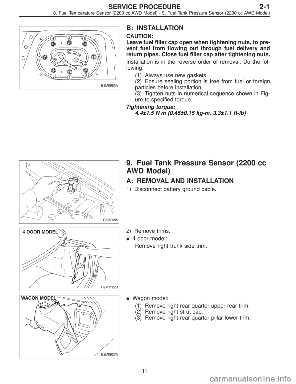
B2M0955A
B: INSTALLATION
CAUTION:
Leave fuel filler cap open when tightening nuts, to pre-
vent fuel from flowing out through fuel delivery and
return pipes. Close fuel filler cap after tightening nuts.
Installation is in the reverse order of removal. Do the fol-
lowing:
(1) Always use new gaskets.
(2) Ensure sealing portion is free from fuel or foreign
particles before installation.
(3) Tighten nuts in numerical sequence shown in Fig-
ure to specified torque.
Tightening torque:
4.4±1.5 N⋅m (0.45±0.15 kg-m, 3.3±1.1 ft-lb)
G6M0095
9. Fuel Tank Pressure Sensor (2200 cc
AWD Model)
A: REMOVAL AND INSTALLATION
1) Disconnect battery ground cable.
H2M1122B
2) Remove trims.
�4 door model:
Remove right trunk side trim.
B2M0927A
�Wagon model:
(1) Remove right rear quarter upper rear trim.
(2) Remove right strut cap.
(3) Remove right rear quarter pillar lower trim.
11
2-1SERVICE PROCEDURE
8. Fuel Temperature Sensor (2200 cc AWD Model) - 9. Fuel Tank Pressure Sensor (2200 cc AWD Model)