Page 1047 of 2890
G4M0544
5) Place transmission jack under rear crossmember.
G4M0545
6) Remove bolts securing crossmember to vehicle body,
and remove crossmember.
7) Scribe an alignment mark on rear lateral link cam bolt
and crossmember.
8) Remove four bolts securing front and rear lateral links
to crossmember by loosening nuts.
B: INSPECTION
Check removed parts for damage and cracks, and correct
or replace if defective.
C: INSTALLATION
1) Install in reverse order of removal.
2) For installation and tightening torque of rear differential,
refer to 3-4 [W2F0].
CAUTION:
Always tighten rubber bushing when wheels are in full
contact with the ground and vehicle is at curb weight
condition.
NOTE:
Check wheel alignment and adjust if necessary.
46
4-1SERVICE PROCEDURE
11. Rear Crossmember (AWD Model)
Page 1048 of 2890
 Permanent distortion or breakage of coil spring Replace.
(2) Unsmooth operation of damper st")
1. Suspension
1. IMPROPER VEHICLE POSTURE OR IMPROPER
WHEEL ARCH HEIGHT
Possible causes Countermeasures
(1) Permanent distortion or breakage of coil spring Replace.
(2) Unsmooth operation of damper strut Replace.
(3) Installation of wrong strut Replace with proper parts.
(4) Installation of wrong coil spring Replace with proper parts.
2. POOR RIDE COMFORT
1) Large rebound shock
2) Rocking of vehicle continues too long after running over
bump and/or hump.
3) Large shock in bumping
Possible causes Countermeasures
(1) Breakage of coil spring Replace.
(2) Over-inflation pressure of tire Adjust.
(3) Improper wheel arch height Adjust or replace coil springs with new ones.
(4) Fault in operation of damper strut Replace.
(5) Damage or deformation of strut mount Replace.
(6) Unsuitability of maximum and/or minimum length of
damper strutReplace with proper parts.
(7) Deformation or loss of bushing Replace.
(8) Deformation or damage of helper in strut assembly Replace.
(9) Oil leakage of damper strut Replace.
3. NOISE
Possible causes Countermeasures
(1) Wear or damage of damper strut component parts Replace.
(2) Loosening of suspension link installing bolt and/or nut Retighten to the specified torque.
(3) Deformation or loss of bushing Replace.
(4) Unsuitability of maximum and/or minimum length of
damper strutReplace with proper parts.
(5) Breakage of coil spring Replace.
(6) Wear or damage of ball joint Replace.
(7) Deformation of stabilizer clamp Replace.
47
4-1DIAGNOSTICS
1. Suspension
Page 1052 of 2890
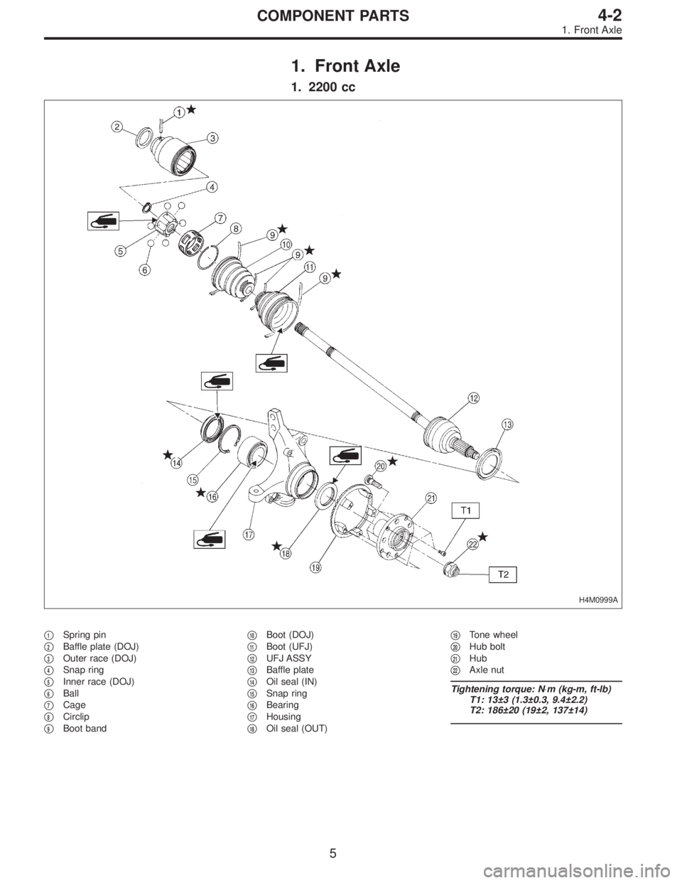
1. Front Axle
1. 2200 cc
H4M0999A
�1Spring pin
�
2Baffle plate (DOJ)
�
3Outer race (DOJ)
�
4Snap ring
�
5Inner race (DOJ)
�
6Ball
�
7Cage
�
8Circlip
�
9Boot band�
10Boot (DOJ)
�
11Boot (UFJ)
�
12UFJ ASSY
�
13Baffle plate
�
14Oil seal (IN)
�
15Snap ring
�
16Bearing
�
17Housing
�
18Oil seal (OUT)�
19Tone wheel
�
20Hub bolt
�
21Hub
�
22Axle nut
Tightening torque: N⋅m (kg-m, ft-lb)
T1: 13±3 (1.3±0.3, 9.4±2.2)
T2: 186±20 (19±2, 137±14)
5
4-2COMPONENT PARTS
1. Front Axle
Page 1053 of 2890
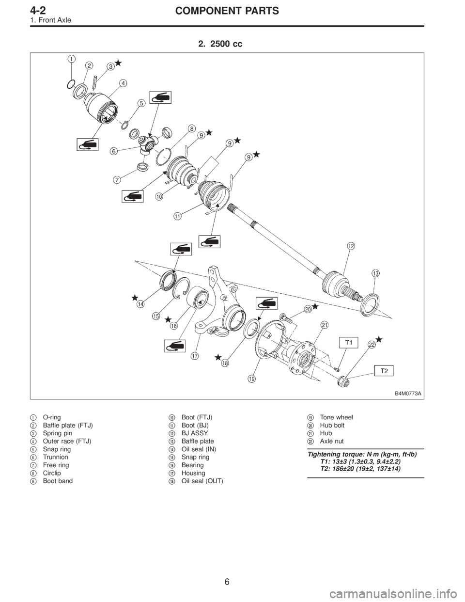
2. 2500 cc
B4M0773A
�1O-ring
�
2Baffle plate (FTJ)
�
3Spring pin
�
4Outer race (FTJ)
�
5Snap ring
�
6Trunnion
�
7Free ring
�
8Circlip
�
9Boot band�
10Boot (FTJ)
�
11Boot (BJ)
�
12BJ ASSY
�
13Baffle plate
�
14Oil seal (IN)
�
15Snap ring
�
16Bearing
�
17Housing
�
18Oil seal (OUT)�
19Tone wheel
�
20Hub bolt
�
21Hub
�
22Axle nut
Tightening torque: N⋅m (kg-m, ft-lb)
T1: 13±3 (1.3±0.3, 9.4±2.2)
T2: 186±20 (19±2, 137±14)
6
4-2COMPONENT PARTS
1. Front Axle
Page 1054 of 2890
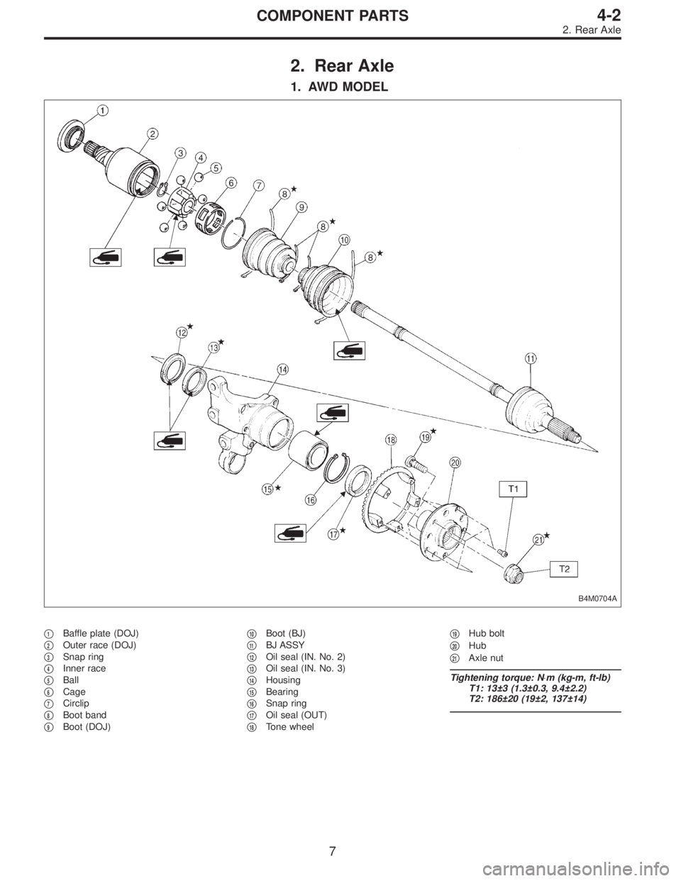
2. Rear Axle
1. AWD MODEL
B4M0704A
�1Baffle plate (DOJ)
�
2Outer race (DOJ)
�
3Snap ring
�
4Inner race
�
5Ball
�
6Cage
�
7Circlip
�
8Boot band
�
9Boot (DOJ)�
10Boot (BJ)
�
11BJ ASSY
�
12Oil seal (IN. No. 2)
�
13Oil seal (IN. No. 3)
�
14Housing
�
15Bearing
�
16Snap ring
�
17Oil seal (OUT)
�
18Tone wheel�
19Hub bolt
�
20Hub
�
21Axle nut
Tightening torque: N⋅m (kg-m, ft-lb)
T1: 13±3 (1.3±0.3, 9.4±2.2)
T2: 186±20 (19±2, 137±14)
7
4-2COMPONENT PARTS
2. Rear Axle
Page 1062 of 2890
 Install transverse link ball joint to housing.
Tightening torque:
44±6 N⋅m (4.5±0.6 kg-m, 32.5±4.3 ft-lb)
2) While aligning alignment mark on camber adjusting bolt
head, connec")
E: INSTALLATION
1) Install transverse link ball joint to housing.
Tightening torque:
44±6 N⋅m (4.5±0.6 kg-m, 32.5±4.3 ft-lb)
2) While aligning alignment mark on camber adjusting bolt
head, connect housing and strut.
CAUTION:
Use a new self-locking nut.
Tightening torque:
147±15 N⋅m (15±1.5 kg-m, 108±11 ft-lb)
3) Install speed sensor and harness on housing (only
vehicle equipped with A.B.S.).
4) Install disc rotor on hub.
5) Install disc brake caliper on housing.
Tightening torque:
59±10 N⋅m (6±1 kg-m, 43±7 ft-lb)
6) Install front drive shaft.
7) Connect stabilizer link.
G4M0236
8) Install tie-rod end ball joint on housing knuckle arm.
Tightening torque:
27.0±2.5 N⋅m (2.75±0.25 kg-m, 19.9±1.8 ft-lb)
G4M0237
9) While depressing brake pedal, tighten axle nut and lock
it securely.
Tightening torque:
186±20 N⋅m (19±2 kg-m, 137±14 ft-lb)
CAUTION:
�Use a new axle nut.
�Always tighten axle nut before installing wheel on
vehicle. If wheel is installed and comes in contact with
ground when axle nut is loose, wheel bearings may be
damaged.
�Be sure to tighten axle nut to specified torque. Do
not overtighten it as this may damage wheel bearing.
15
4-2SERVICE PROCEDURE
1. Front Axle
Page 1063 of 2890
G4M0238
10) After tightening axle nut, lock it securely.
11) Install wheel and tighten wheel nuts to specified
torque.
Tightening torque:
88±10 N⋅m (9±1 kg-m, 65±7 ft-lb)
2. Rear Axle (AWD Model)
A: REMOVAL
1) Disconnect ground cable from battery.
2) Jack-up vehicle, and remove rear wheel cap and
wheels.
CAUTION:
Be sure to loosen and retighten axle nut after remov-
ing wheel from vehicle. Failure to follow this rule may
damage wheel bearings.
3) Unlock axle nut.
4) Remove axle nut using a socket wrench.
B4M0050A
5) Return parking brake lever and loosen adjusting nut.
(1) Disc brake: Perform steps 6) and 7).
(2) Drum brake: Perform steps 8) through 10).
G4M0240
6) Remove disc brake caliper from back plate, and sus-
pend it from strut using a piece of wire.
7) Remove disc rotor from hub.
NOTE:
If disc rotor seizes up within hub, drive it out by installing
an 8-mm bolt into bolt hole in disc rotor.
16
4-2SERVICE PROCEDURE
1. Front Axle - 2. Rear Axle (AWD Model)
Page 1064 of 2890
G4M0238
10) After tightening axle nut, lock it securely.
11) Install wheel and tighten wheel nuts to specified
torque.
Tightening torque:
88±10 N⋅m (9±1 kg-m, 65±7 ft-lb)
2. Rear Axle (AWD Model)
A: REMOVAL
1) Disconnect ground cable from battery.
2) Jack-up vehicle, and remove rear wheel cap and
wheels.
CAUTION:
Be sure to loosen and retighten axle nut after remov-
ing wheel from vehicle. Failure to follow this rule may
damage wheel bearings.
3) Unlock axle nut.
4) Remove axle nut using a socket wrench.
B4M0050A
5) Return parking brake lever and loosen adjusting nut.
(1) Disc brake: Perform steps 6) and 7).
(2) Drum brake: Perform steps 8) through 10).
G4M0240
6) Remove disc brake caliper from back plate, and sus-
pend it from strut using a piece of wire.
7) Remove disc rotor from hub.
NOTE:
If disc rotor seizes up within hub, drive it out by installing
an 8-mm bolt into bolt hole in disc rotor.
16
4-2SERVICE PROCEDURE
1. Front Axle - 2. Rear Axle (AWD Model)
 Place transmission jack under rear crossmember.
G4M0545
6) Remove bolts securing crossmember to vehicle body,
and remove crossmember.
7) Scribe an alignment mark on rear lateral link cam bo")
 After tightening axle nut, lock it securely.
11) Install wheel and tighten wheel nuts to specified
torque.
Tightening torque:
88±10 N⋅m (9±1 kg-m, 65±7 ft-lb)
2. Rear Axle (AWD Model)")
 After tightening axle nut, lock it securely.
11) Install wheel and tighten wheel nuts to specified
torque.
Tightening torque:
88±10 N⋅m (9±1 kg-m, 65±7 ft-lb)
2. Rear Axle (AWD Model)")