Page 733 of 2890

B: INSTALLATION
1. Install engine to transmission.
2. Tighten bolts which hold upper side of transmission to engine.
3. Remove lifting device and wire rope.
4. Remove garage jack.
5. Install pitching stopper.
AT model
6. Install torque converter onto drive plate.
7. Install canister and bracket.
8. Install power steering pump on bracket.
9. Tighten nuts which hold lower side of transmission to engine.
10. Tighten nuts which install front cushion rubber onto cross-
member.
11. Install front exhaust pipe and center exhaust pipe.
12. Connect hoses, connectors and cables.
13. Install air intake system.
�Air intake duct
�Air cleaner element and upper cover.
With A/C
14. Install A/C pressure hoses.
15. Install cooling system.
16. Install battery onto the vehicle, and connect cables.
17. Fill coolant.
18. Check ATF level, and connect if necessary. [AT]
19. Correct power steering oil, and bleed air.
20. Remove front hood stay, and close front hood.
21. Take off the vehicle from lift arms.
�
�
�
�
�
�
�
�
�
�
�
�
20
2-11SERVICE PROCEDURE
2. Engine
Page 734 of 2890
G2M0301
1) Install engine onto transmission.
(1) Position engine in engine compartment and align it
with transmission.
CAUTION:
Be careful not to damage adjacent parts or body pan-
els with crank pulley, oil pressure gauge, etc.
(2) Apply a small amount of grease to spline of main-
shaft.
G2M0299
2) Tighten bolts which hold upper side of transmission to
engine.
Tightening torque:
50±4 N⋅m (5.1±0.4 kg-m, 36.9±2.9 ft-lb)
G2M0297
3) Remove lifting device and wire ropes.
4) Remove garage jack.
21
2-11SERVICE PROCEDURE
2. Engine
Page 746 of 2890
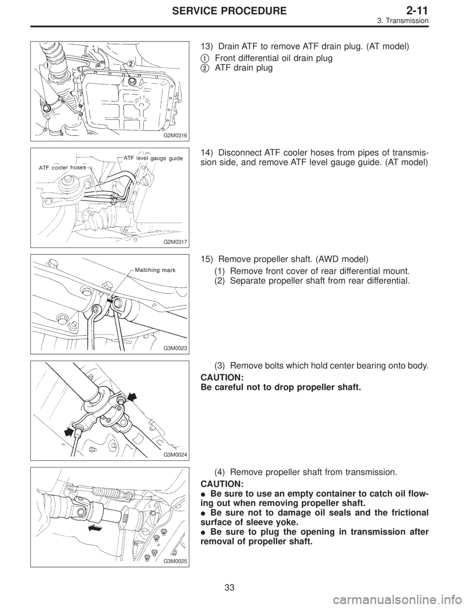
G2M0316
13) Drain ATF to remove ATF drain plug. (AT model)
�
1Front differential oil drain plug
�
2ATF drain plug
G2M0317
14) Disconnect ATF cooler hoses from pipes of transmis-
sion side, and remove ATF level gauge guide. (AT model)
G3M0023
15) Remove propeller shaft. (AWD model)
(1) Remove front cover of rear differential mount.
(2) Separate propeller shaft from rear differential.
G3M0024
(3) Remove bolts which hold center bearing onto body.
CAUTION:
Be careful not to drop propeller shaft.
G3M0025
(4) Remove propeller shaft from transmission.
CAUTION:
�Be sure to use an empty container to catch oil flow-
ing out when removing propeller shaft.
�Be sure not to damage oil seals and the frictional
surface of sleeve yoke.
�Be sure to plug the opening in transmission after
removal of propeller shaft.
33
2-11SERVICE PROCEDURE
3. Transmission
Page 748 of 2890
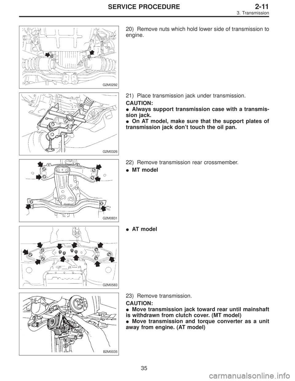
G2M0292
20) Remove nuts which hold lower side of transmission to
engine.
G2M0326
21) Place transmission jack under transmission.
CAUTION:
�Always support transmission case with a transmis-
sion jack.
�On AT model, make sure that the support plates of
transmission jack don’t touch the oil pan.
G2M0831
22) Remove transmission rear crossmember.
�MT model
G2M0583
�AT model
B2M0035
23) Remove transmission.
CAUTION:
�Move transmission jack toward rear until mainshaft
is withdrawn from clutch cover. (MT model)
�Move transmission and torque converter as a unit
away from engine. (AT model)
35
2-11SERVICE PROCEDURE
3. Transmission
Page 758 of 2890
1. Manual Transmission and
Differential
A: SPECIFICATIONS
ItemModel
FWD AWD
2200 cc 2200 cc*2200 cc
OUTBACK
Type 5-forward speeds with synchromesh and 1-reverse
Transmission gear ratio1st 3.545
2nd 2.111
3rd 1.448
4th 1.088
5th 0.825 0.780 0.871
Reverse 3.416
Front
reduction
gearFinalType of gear Hypoid
Gear ratio 3.454 3.900 4.111
Rear
reduction
gearTransferType of gear — Helical
Gear ratio — 1.000
FinalType of gear — Hypoid
Gear ratio — 3.900 4.111
Front
differentialType and number of gear Straight bevel gear (Bevel pinion: 2, Bevel gear: 2)
Center
differentialType and number of gear —Straight bevel gear
(Bevel pinion: 2, Bevel gear: 2 and viscous coupling)
Transmission gear oil GL-5
Transmission oil capacity3.3�(3.5 US qt, 2.9 Imp
qt)3.5�(3.7 US qt, 3.1 Imp qt)
*: Step roof model only
2
3-1SPECIFICATIONS AND SERVICE DATA
1. Manual Transmission and Differential
Page 764 of 2890
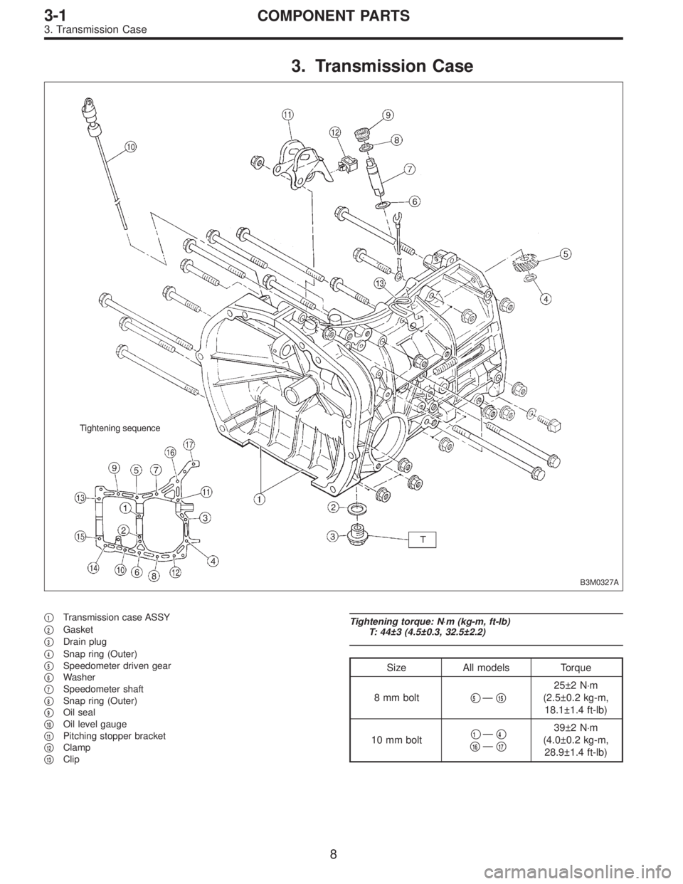
3. Transmission Case
B3M0327A
�1Transmission case ASSY
�
2Gasket
�
3Drain plug
�
4Snap ring (Outer)
�
5Speedometer driven gear
�
6Washer
�
7Speedometer shaft
�
8Snap ring (Outer)
�
9Oil seal
�
10Oil level gauge
�
11Pitching stopper bracket
�
12Clamp
�
13Clip
Tightening torque: N⋅m (kg-m, ft-lb)
T: 44±3 (4.5±0.3, 32.5±2.2)
Size All models Torque
8 mm bolt�
5—�15
25±2 N⋅m
(2.5±0.2 kg-m,
18.1±1.4 ft-lb)
10 mm bolt�
1—�4
�16—�17
39±2 N⋅m
(4.0±0.2 kg-m,
28.9±1.4 ft-lb)
8
3-1COMPONENT PARTS
3. Transmission Case
Page 768 of 2890
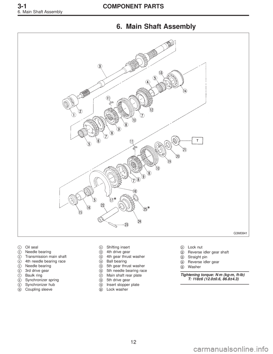
6. Main Shaft Assembly
G3M0841
�1Oil seal
�
2Needle bearing
�
3Transmission main shaft
�
44th needle bearing race
�
5Needle bearing
�
63rd drive gear
�
7Baulk ring
�
8Synchronizer spring
�
9Synchronizer hub
�
10Coupling sleeve�
11Shifting insert
�
124th drive gear
�
134th gear thrust washer
�
14Ball bearing
�
155th gear thrust washer
�
165th needle bearing race
�
17Main shaft rear plate
�
185th drive gear
�
19Insert stopper plate
�
20Lock washer�
21Lock nut
�
22Reverse idler gear shaft
�
23Straight pin
�
24Reverse idler gear
�
25Washer
Tightening torque: N⋅m (kg-m, ft-lb)
T: 118±6 (12.0±0.6, 86.8±4.3)
12
3-1COMPONENT PARTS
6. Main Shaft Assembly
Page 772 of 2890
 The following job should be followed before disassem-
bly:
(1) Clean oil, grease, dirt and dust from transmission.
(2) Remove drain plug�
1to drain oil. After draining,
reti")
B3M0037A
B: PRECAUTIONS
1) The following job should be followed before disassem-
bly:
(1) Clean oil, grease, dirt and dust from transmission.
(2) Remove drain plug�
1to drain oil. After draining,
retighten it as before.
CAUTION:
Replace gasket with a new one.
Tightening torque:
44±3 N⋅m (4.5±0.3 kg-m, 32.5±2.2 ft-lb)
G3M0517
(3) Attach transmission to ST.
ST 499937100 TRANSMISSION STAND SET
2) Rotating parts should be coated with oil prior to assem-
bly.
3) All disassembled parts, if to be reused, should be rein-
stalled in the original positions and directions.
4) Gaskets and lock washers must be replaced with new
ones.
5) Liquid gasket should be used where specified to pre-
vent leakage.
6) Fill transmission gear oil through the oil level gauge
hole up to upper point level gauge.
C: INSPECTION
Disassembled parts should be washed clean first and then
inspected carefully.
1) Bearings
Replace bearings in the following cases:
�Bearings whose balls, outer races and inner races are
broken or rusty.
�Worn bearings
�Bearings that fail to turn smoothly or make abnormal
noise when turned after gear oil lubrication.
B3M0038A
The ball bearing�3on the rear side of the drive pinion shaft
�
2should be checked for smooth rotation before the drive
pinion assembly is disassembled. In this case, because a
preload is working on the bearing, its rotation feels like it is
slightly dragging unlike the other bearings.
�Bearings having other defects
16
3-1SERVICE PROCEDURE
1. General
 Install engine onto transmission.
(1) Position engine in engine compartment and align it
with transmission.
CAUTION:
Be careful not to damage adjacent parts or body pan-
els with crank pull")