Page 1238 of 2890
G4M0379
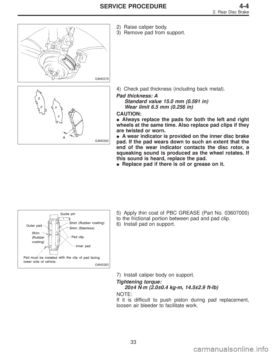
2) Raise caliper body.
3) Remove pad from support.
G4M0362
4) Check pad thickness (including back metal).
Pad thickness: A
Standard value 15.0 mm (0.591 in)
Wear limit 6.5 mm (0.256 in)
CAUTION:
�Always replace the pads for both the left and right
wheels at the same time. Also replace pad clips if they
are twisted or worn.
�A wear indicator is provided on the inner disc brake
pad. If the pad wears down to such an extent that the
end of the wear indicator contacts the disc rotor, a
squeaking sound is produced as the wheel rotates. If
this sound is heard, replace the pad.
�Replace pad if there is oil or grease on it.
G4M0363
5) Apply thin coat of PBC GREASE (Part No. 03607000)
to the frictional portion between pad and pad clip.
6) Install pad on support.
7) Install caliper body on support.
Tightening torque:
20±4 N⋅m (2.0±0.4 kg-m, 14.5±2.9 ft-lb)
NOTE:
If it is difficult to push piston during pad replacement,
loosen air bleeder to facilitate work.
33
4-4SERVICE PROCEDURE
2. Rear Disc Brake
Page 1239 of 2890
G4M0382
2. DISC ROTOR
1) Install disc rotor by tightening the five wheel nuts.
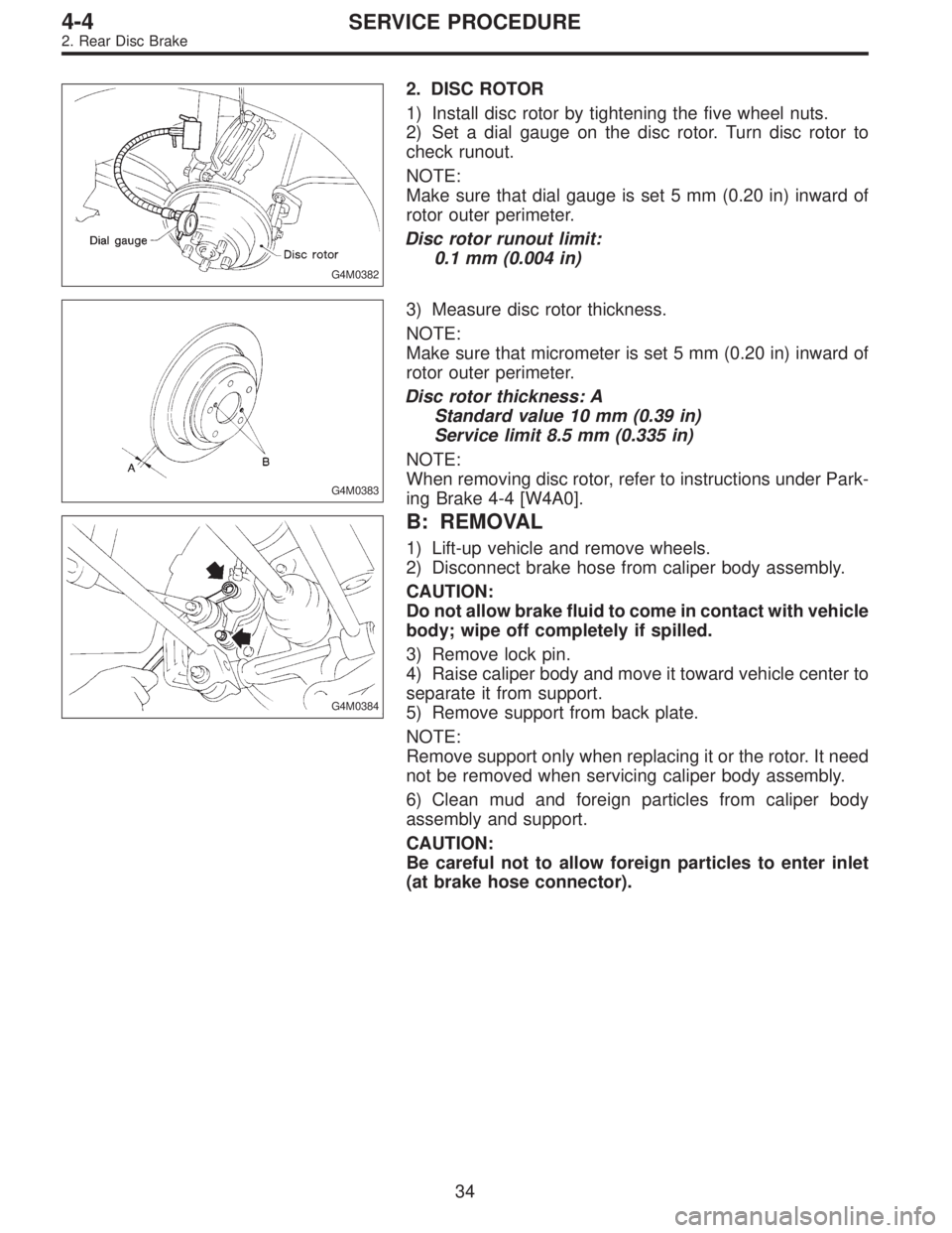
2) Set a dial gauge on the disc rotor. Turn disc rotor to
check runout.
NOTE:
Make sure that dial gauge is set 5 mm (0.20 in) inward of
rotor outer perimeter.
Disc rotor runout limit:
0.1 mm (0.004 in)
G4M0383
3) Measure disc rotor thickness.
NOTE:
Make sure that micrometer is set 5 mm (0.20 in) inward of
rotor outer perimeter.
Disc rotor thickness: A
Standard value 10 mm (0.39 in)
Service limit 8.5 mm (0.335 in)
NOTE:
When removing disc rotor, refer to instructions under Park-
ing Brake 4-4 [W4A0].
G4M0384
B: REMOVAL
1) Lift-up vehicle and remove wheels.
2) Disconnect brake hose from caliper body assembly.
CAUTION:
Do not allow brake fluid to come in contact with vehicle
body; wipe off completely if spilled.
3) Remove lock pin.
4) Raise caliper body and move it toward vehicle center to
separate it from support.
5) Remove support from back plate.
NOTE:
Remove support only when replacing it or the rotor. It need
not be removed when servicing caliper body assembly.
6) Clean mud and foreign particles from caliper body
assembly and support.
CAUTION:
Be careful not to allow foreign particles to enter inlet
(at brake hose connector).
34
4-4SERVICE PROCEDURE
2. Rear Disc Brake
Page 1242 of 2890
F: INSTALLATION
1) Install disc rotor on hub.
2) Install support on back plate.
Tightening torque:
52±6 N⋅m (5.3±0.6 kg-m, 38.3±4.3 ft-lb)
CAUTION:
�Always replace the pads for both the left and right
wheels at the same time. Also replace pad clips if they
are twisted or worn.
�A wear indicator is provided on the inner disc brake
pad. If the pad wears down to such an extent that the
end of the wear indicator contacts the disc rotor, a
squeaking sound is produced as the wheel rotates. If
this sound is heard, replace the pad.
�Replace pads if there is oil or grease on them.
3) Apply thin coat of PBC GREASE (Part No. 003607000)
to the frictional portion between pad and pad clip.
G4M0363
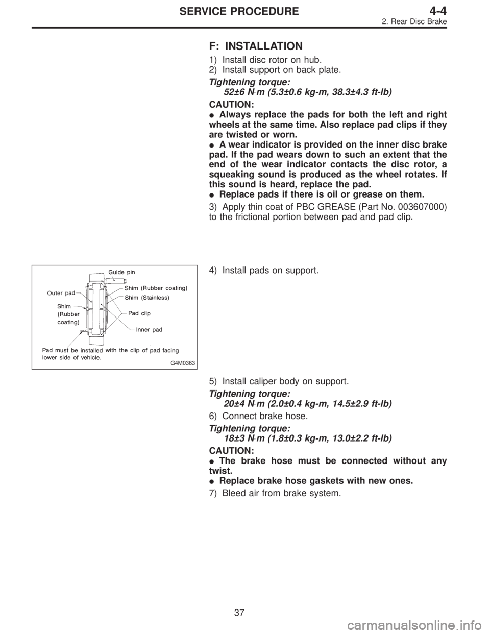
4) Install pads on support.
5) Install caliper body on support.
Tightening torque:
20±4 N⋅m (2.0±0.4 kg-m, 14.5±2.9 ft-lb)
6) Connect brake hose.
Tightening torque:
18±3 N⋅m (1.8±0.3 kg-m, 13.0±2.2 ft-lb)
CAUTION:
�The brake hose must be connected without any
twist.
�Replace brake hose gaskets with new ones.
7) Bleed air from brake system.
37
4-4SERVICE PROCEDURE
2. Rear Disc Brake
Page 1249 of 2890
4. Parking Brake (Rear Disc Brake)
G4M0411
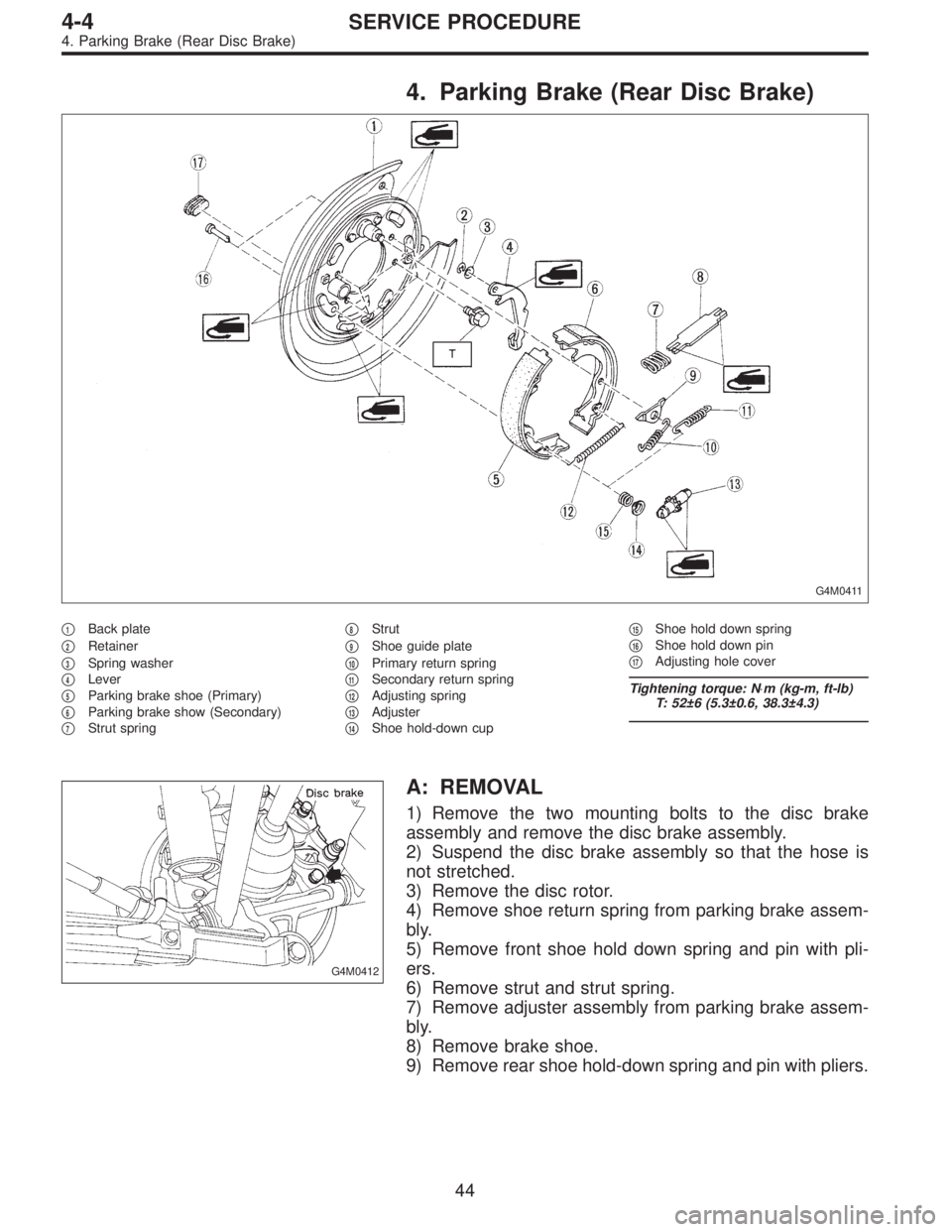
�1Back plate
�
2Retainer
�
3Spring washer
�
4Lever
�
5Parking brake shoe (Primary)
�
6Parking brake show (Secondary)
�
7Strut spring�
8Strut
�
9Shoe guide plate
�
10Primary return spring
�
11Secondary return spring
�
12Adjusting spring
�
13Adjuster
�
14Shoe hold-down cup�
15Shoe hold down spring
�
16Shoe hold down pin
�
17Adjusting hole cover
Tightening torque: N⋅m (kg-m, ft-lb)
T: 52±6 (5.3±0.6, 38.3±4.3)
G4M0412
A: REMOVAL
1) Remove the two mounting bolts to the disc brake
assembly and remove the disc brake assembly.
2) Suspend the disc brake assembly so that the hose is
not stretched.
3) Remove the disc rotor.
4) Remove shoe return spring from parking brake assem-
bly.
5) Remove front shoe hold down spring and pin with pli-
ers.
6) Remove strut and strut spring.
7) Remove adjuster assembly from parking brake assem-
bly.
8) Remove brake shoe.
9) Remove rear shoe hold-down spring and pin with pliers.
44
4-4SERVICE PROCEDURE
4. Parking Brake (Rear Disc Brake)
Page 1252 of 2890
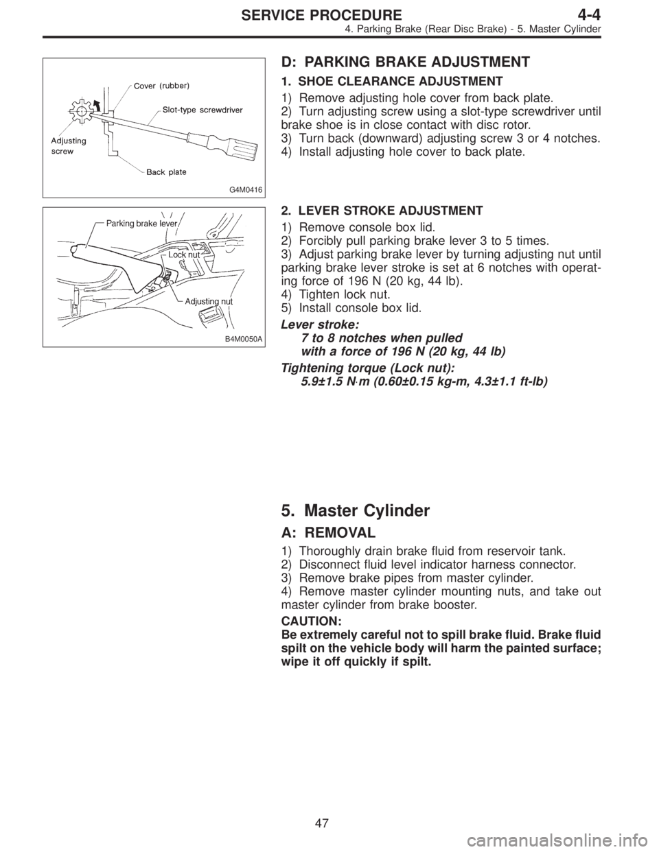
G4M0416
D: PARKING BRAKE ADJUSTMENT
1. SHOE CLEARANCE ADJUSTMENT
1) Remove adjusting hole cover from back plate.
2) Turn adjusting screw using a slot-type screwdriver until
brake shoe is in close contact with disc rotor.
3) Turn back (downward) adjusting screw 3 or 4 notches.
4) Install adjusting hole cover to back plate.
B4M0050A
2. LEVER STROKE ADJUSTMENT
1) Remove console box lid.
2) Forcibly pull parking brake lever 3 to 5 times.
3) Adjust parking brake lever by turning adjusting nut until
parking brake lever stroke is set at 6 notches with operat-
ing force of 196 N (20 kg, 44 lb).
4) Tighten lock nut.
5) Install console box lid.
Lever stroke:
7 to 8 notches when pulled
with a force of 196 N (20 kg, 44 lb)
Tightening torque (Lock nut):
5.9±1.5 N⋅m (0.60±0.15 kg-m, 4.3±1.1 ft-lb)
5. Master Cylinder
A: REMOVAL
1) Thoroughly drain brake fluid from reservoir tank.
2) Disconnect fluid level indicator harness connector.
3) Remove brake pipes from master cylinder.
4) Remove master cylinder mounting nuts, and take out
master cylinder from brake booster.
CAUTION:
Be extremely careful not to spill brake fluid. Brake fluid
spilt on the vehicle body will harm the painted surface;
wipe it off quickly if spilt.
47
4-4SERVICE PROCEDURE
4. Parking Brake (Rear Disc Brake) - 5. Master Cylinder
Page 1253 of 2890
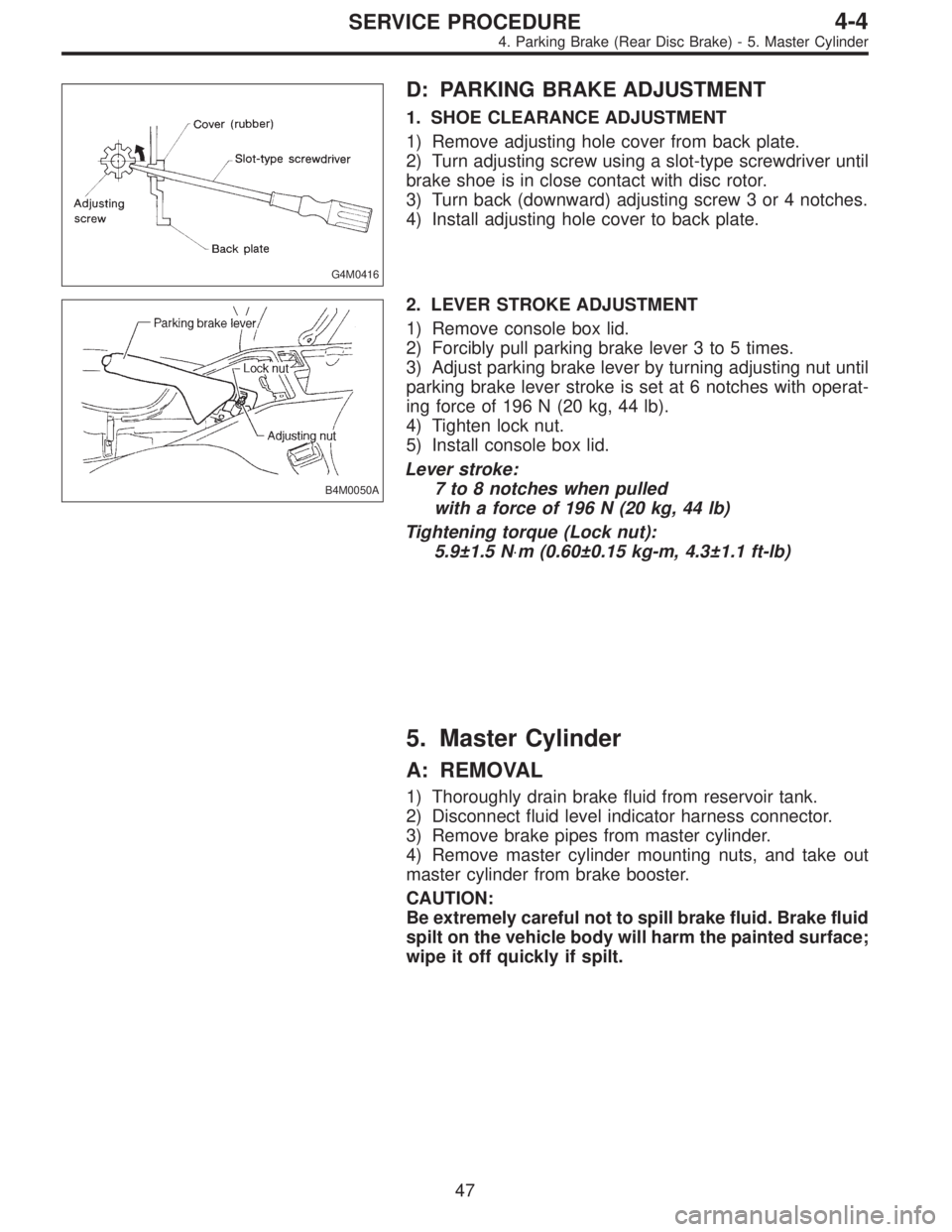
G4M0416
D: PARKING BRAKE ADJUSTMENT
1. SHOE CLEARANCE ADJUSTMENT
1) Remove adjusting hole cover from back plate.
2) Turn adjusting screw using a slot-type screwdriver until
brake shoe is in close contact with disc rotor.
3) Turn back (downward) adjusting screw 3 or 4 notches.
4) Install adjusting hole cover to back plate.
B4M0050A
2. LEVER STROKE ADJUSTMENT
1) Remove console box lid.
2) Forcibly pull parking brake lever 3 to 5 times.
3) Adjust parking brake lever by turning adjusting nut until
parking brake lever stroke is set at 6 notches with operat-
ing force of 196 N (20 kg, 44 lb).
4) Tighten lock nut.
5) Install console box lid.
Lever stroke:
7 to 8 notches when pulled
with a force of 196 N (20 kg, 44 lb)
Tightening torque (Lock nut):
5.9±1.5 N⋅m (0.60±0.15 kg-m, 4.3±1.1 ft-lb)
5. Master Cylinder
A: REMOVAL
1) Thoroughly drain brake fluid from reservoir tank.
2) Disconnect fluid level indicator harness connector.
3) Remove brake pipes from master cylinder.
4) Remove master cylinder mounting nuts, and take out
master cylinder from brake booster.
CAUTION:
Be extremely careful not to spill brake fluid. Brake fluid
spilt on the vehicle body will harm the painted surface;
wipe it off quickly if spilt.
47
4-4SERVICE PROCEDURE
4. Parking Brake (Rear Disc Brake) - 5. Master Cylinder
Page 1274 of 2890
14. ABS Sensor
A: REMOVAL
1. FRONT ABS SENSOR
1) Disconnect front ABS sensor connector located in
engine compartment.
B4M0079A
2) Remove bolts which secure sensor harness to strut.
G4M0451
3) Remove bolts which secure sensor harness to body.
G4M0443
4) Remove bolts which secure front ABS sensor to
housing, and remove front ABS sensor.
CAUTION:
�Be careful not to damage pole piece located at tip of
the sensor and teeth faces during removal.
�Do not pull sensor harness during removal.
5) Remove front disc brake caliper and disc rotor from
housing after removing front tire.
6) Remove front drive shaft and housing and hub assem-
bly.
67
4-4SERVICE PROCEDURE
14. ABS Sensor
Page 1335 of 2890
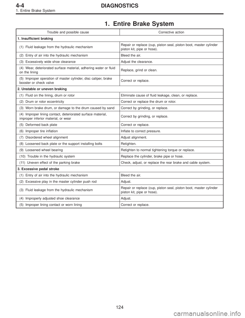
1. Entire Brake System
Trouble and possible cause Corrective action
1. Insufficient braking
(1) Fluid leakage from the hydraulic mechanismRepair or replace (cup, piston seal, piston boot, master cylinder
piston kit, pipe or hose).
(2) Entry of air into the hydraulic mechanism Bleed the air.
(3) Excessively wide shoe clearance Adjust the clearance.
(4) Wear, deteriorated surface material, adhering water or fluid
on the liningReplace, grind or clean.
(5) Improper operation of master cylinder, disc caliper, brake
booster or check valveCorrect or replace.
2. Unstable or uneven braking
(1) Fluid on the lining, drum or rotor Eliminate cause of fluid leakage, clean, or replace.
(2) Drum or rotor eccentricity Correct or replace the drum or rotor.
(3) Worn brake drum, or damage to the drum caused by sand Correct by grinding, or replace.
(4) Improper lining contact, deteriorated surface material,
improper inferior material, or wearCorrect by grinding, or replace.
(5) Deformed back plate Correct or replace.
(6) Improper tire inflation Inflate to correct pressure.
(7) Disordered wheel alignment Adjust alignment.
(8) Loosened back plate or the support installing bolts Retighten.
(9) Loosened wheel bearing Retighten to normal tightening torque or replace.
(10) Trouble in the hydraulic system Replace the cylinder, brake pipe or hose.
(11) Uneven effect of the parking brake Check, adjust, or replace the rear brake and cable system.
3. Excessive pedal stroke
(1) Entry of air into the hydraulic mechanism Bleed the air.
(2) Excessive play in the master cylinder push rod Adjust.
(3) Fluid leakage from the hydraulic mechanismRepair or replace (cup, piston seal, piston boot, master cylinder
piston kit, pipe or hose).
(4) Improperly adjusted shoe clearance Adjust.
(5) Improper lining contact or worn lining Correct or replace.
124
4-4DIAGNOSTICS
1. Entire Brake System