Page 592 of 2890

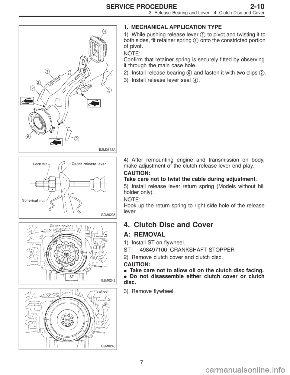
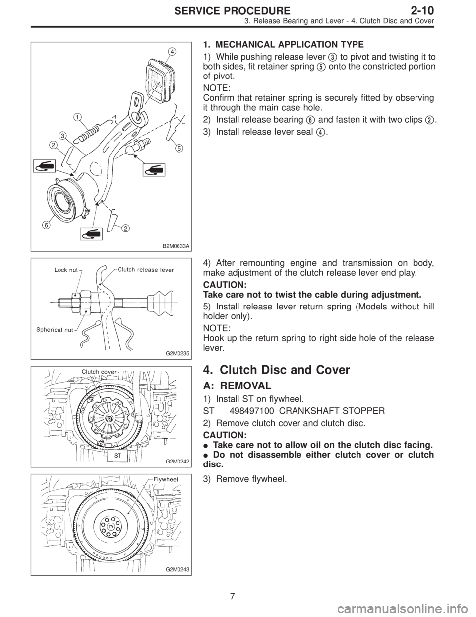
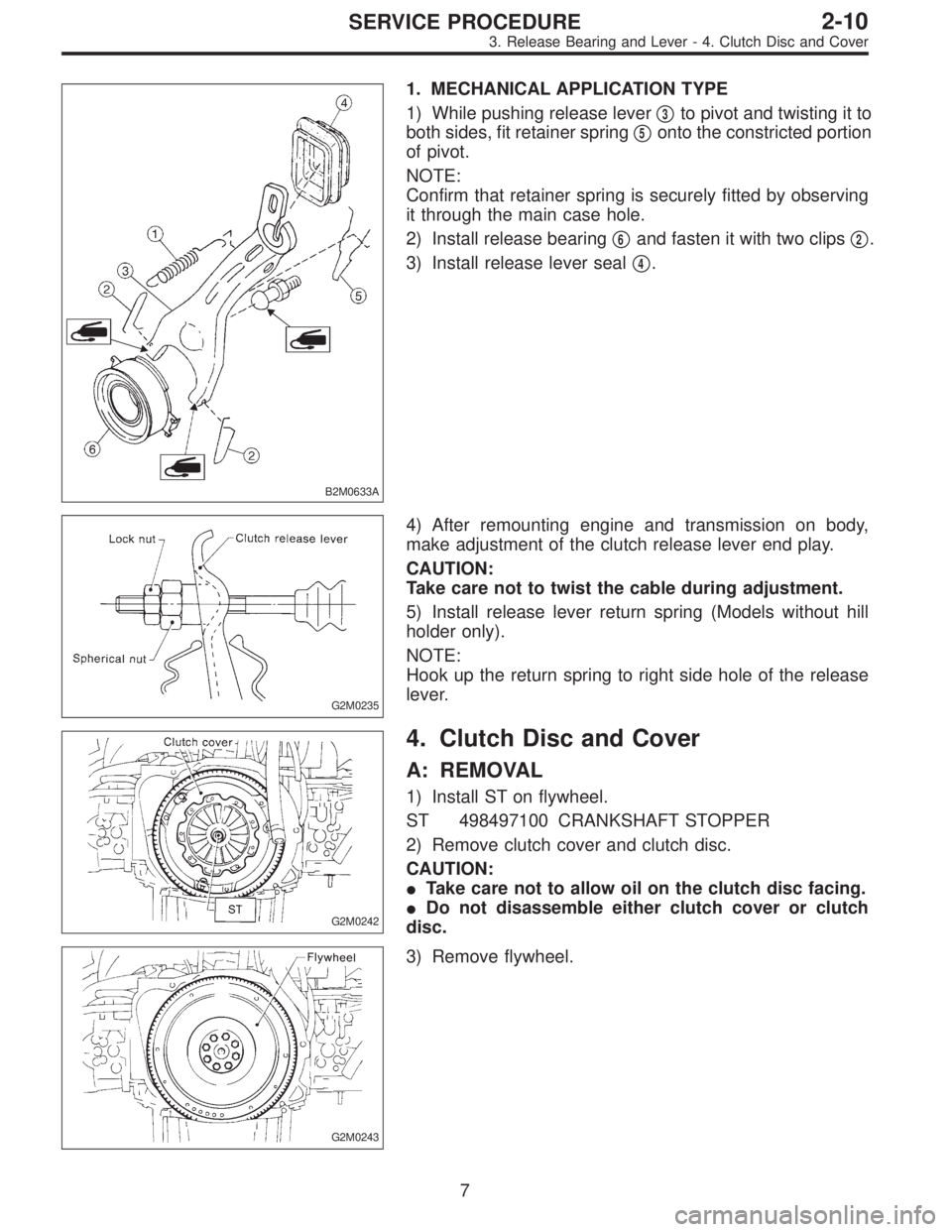
B2M0633A
1. MECHANICAL APPLICATION TYPE
1) While pushing release lever�
3to pivot and twisting it to
both sides, fit retainer spring�
5onto the constricted portion
of pivot.
NOTE:
Confirm that retainer spring is securely fitted by observing
it through the main case hole.
2) Install release bearing�
6and fasten it with two clips�2.
3) Install release lever seal�
4.
G2M0235
4) After remounting engine and transmission on body,
make adjustment of the clutch release lever end play.
CAUTION:
Take care not to twist the cable during adjustment.
5) Install release lever return spring (Models without hill
holder only).
NOTE:
Hook up the return spring to right side hole of the release
lever.
G2M0242
4. Clutch Disc and Cover
A: REMOVAL
1) Install ST on flywheel.
ST 498497100 CRANKSHAFT STOPPER
2) Remove clutch cover and clutch disc.
CAUTION:
�Take care not to allow oil on the clutch disc facing.
�Do not disassemble either clutch cover or clutch
disc.
G2M0243
3) Remove flywheel.
7
2-10SERVICE PROCEDURE
3. Release Bearing and Lever - 4. Clutch Disc and Cover
Page 707 of 2890

B2M0633A
1. MECHANICAL APPLICATION TYPE
1) While pushing release lever�
3to pivot and twisting it to
both sides, fit retainer spring�
5onto the constricted portion
of pivot.
NOTE:
Confirm that retainer spring is securely fitted by observing
it through the main case hole.
2) Install release bearing�
6and fasten it with two clips�2.
3) Install release lever seal�
4.
G2M0235
4) After remounting engine and transmission on body,
make adjustment of the clutch release lever end play.
CAUTION:
Take care not to twist the cable during adjustment.
5) Install release lever return spring (Models without hill
holder only).
NOTE:
Hook up the return spring to right side hole of the release
lever.
G2M0242
4. Clutch Disc and Cover
A: REMOVAL
1) Install ST on flywheel.
ST 498497100 CRANKSHAFT STOPPER
2) Remove clutch cover and clutch disc.
CAUTION:
�Take care not to allow oil on the clutch disc facing.
�Do not disassemble either clutch cover or clutch
disc.
G2M0243
3) Remove flywheel.
7
2-10SERVICE PROCEDURE
3. Release Bearing and Lever - 4. Clutch Disc and Cover
Page 708 of 2890

B2M0633A
1. MECHANICAL APPLICATION TYPE
1) While pushing release lever�
3to pivot and twisting it to
both sides, fit retainer spring�
5onto the constricted portion
of pivot.
NOTE:
Confirm that retainer spring is securely fitted by observing
it through the main case hole.
2) Install release bearing�
6and fasten it with two clips�2.
3) Install release lever seal�
4.
G2M0235
4) After remounting engine and transmission on body,
make adjustment of the clutch release lever end play.
CAUTION:
Take care not to twist the cable during adjustment.
5) Install release lever return spring (Models without hill
holder only).
NOTE:
Hook up the return spring to right side hole of the release
lever.
G2M0242
4. Clutch Disc and Cover
A: REMOVAL
1) Install ST on flywheel.
ST 498497100 CRANKSHAFT STOPPER
2) Remove clutch cover and clutch disc.
CAUTION:
�Take care not to allow oil on the clutch disc facing.
�Do not disassemble either clutch cover or clutch
disc.
G2M0243
3) Remove flywheel.
7
2-10SERVICE PROCEDURE
3. Release Bearing and Lever - 4. Clutch Disc and Cover
Page 758 of 2890
1. Manual Transmission and
Differential
A: SPECIFICATIONS
ItemModel
FWD AWD
2200 cc 2200 cc*2200 cc
OUTBACK
Type 5-forward speeds with synchromesh and 1-reverse
Transmission gear ratio1st 3.545
2nd 2.111
3rd 1.448
4th 1.088
5th 0.825 0.780 0.871
Reverse 3.416
Front
reduction
gearFinalType of gear Hypoid
Gear ratio 3.454 3.900 4.111
Rear
reduction
gearTransferType of gear — Helical
Gear ratio — 1.000
FinalType of gear — Hypoid
Gear ratio — 3.900 4.111
Front
differentialType and number of gear Straight bevel gear (Bevel pinion: 2, Bevel gear: 2)
Center
differentialType and number of gear —Straight bevel gear
(Bevel pinion: 2, Bevel gear: 2 and viscous coupling)
Transmission gear oil GL-5
Transmission oil capacity3.3�(3.5 US qt, 2.9 Imp
qt)3.5�(3.7 US qt, 3.1 Imp qt)
*: Step roof model only
2
3-1SPECIFICATIONS AND SERVICE DATA
1. Manual Transmission and Differential
Page 829 of 2890

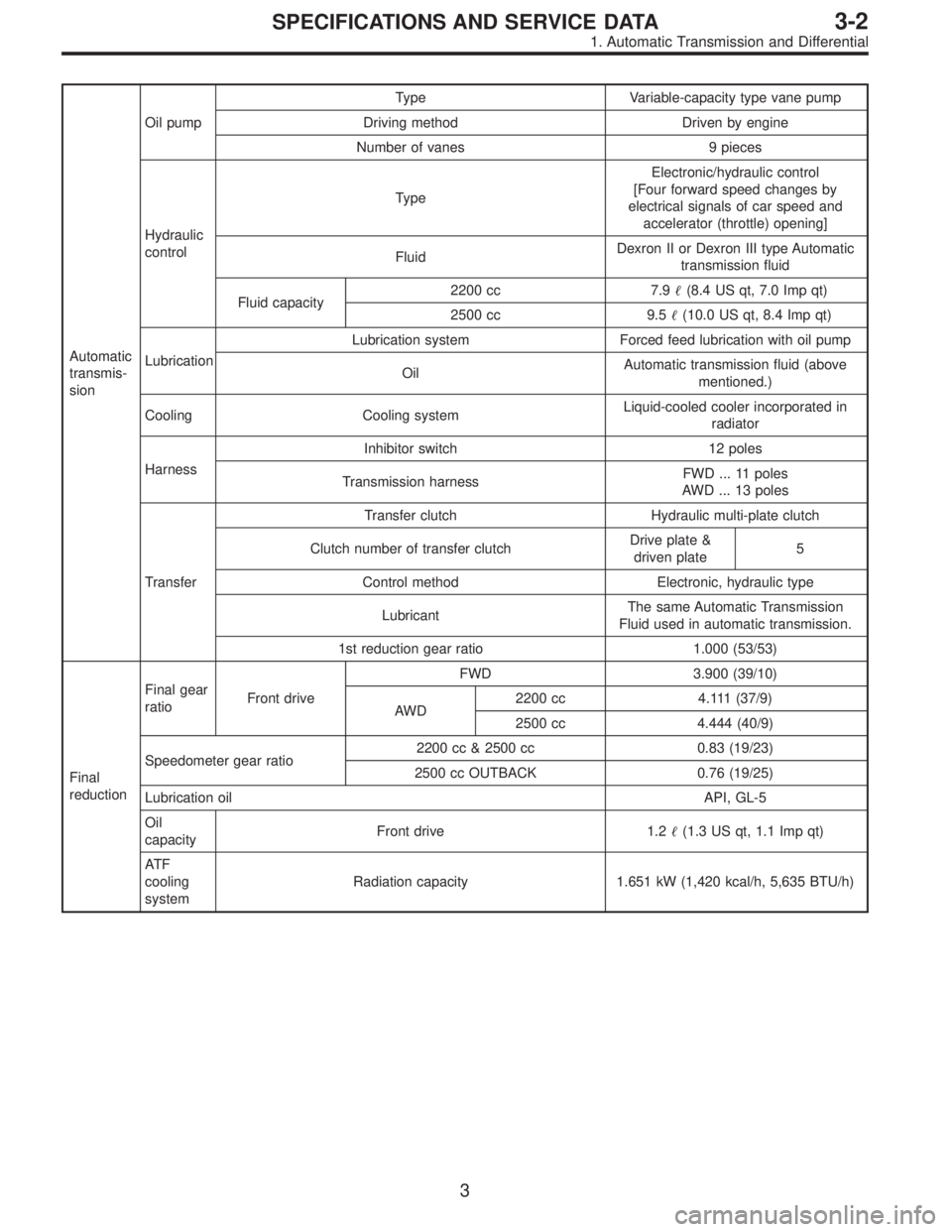
Automatic
transmis-
sionOil pumpType Variable-capacity type vane pump
Driving method Driven by engine
Number of vanes 9 pieces
Hydraulic
controlTypeElectronic/hydraulic control
[Four forward speed changes by
electrical signals of car speed and
accelerator (throttle) opening]
FluidDexron II or Dexron III type Automatic
transmission fluid
Fluid capacity2200 cc 7.9�(8.4 US qt, 7.0 Imp qt)
2500 cc 9.5�(10.0 US qt, 8.4 Imp qt)
LubricationLubrication system Forced feed lubrication with oil pump
OilAutomatic transmission fluid (above
mentioned.)
Cooling Cooling systemLiquid-cooled cooler incorporated in
radiator
HarnessInhibitor switch 12 poles
Transmission harnessFWD ... 11 poles
AWD ... 13 poles
TransferTransfer clutch Hydraulic multi-plate clutch
Clutch number of transfer clutchDrive plate &
driven plate5
Control method Electronic, hydraulic type
LubricantThe same Automatic Transmission
Fluid used in automatic transmission.
1st reduction gear ratio 1.000 (53/53)
Final
reductionFinal gear
ratioFront driveFWD 3.900 (39/10)
AWD2200 cc 4.111 (37/9)
2500 cc 4.444 (40/9)
Speedometer gear ratio2200 cc & 2500 cc 0.83 (19/23)
2500 cc OUTBACK 0.76 (19/25)
Lubrication oilAPI, GL-5
Oil
capacityFront drive 1.2�(1.3 US qt, 1.1 Imp qt)
AT F
cooling
systemRadiation capacity 1.651 kW (1,420 kcal/h, 5,635 BTU/h)
3
3-2SPECIFICATIONS AND SERVICE DATA
1. Automatic Transmission and Differential
Page 961 of 2890
1. AWD System
A: SPECIFICATIONS
1. REAR FINAL REDUCTION GEAR RATIO
Type of gearHypoid
MT AT
2200 cc*2200 cc
OUTBACK2200 cc 2500 cc
Gear ratio
(Number of
gear teeth)3.900
(39/10)4 . 111
(37/9)4 . 111
(37/9)4.444
(40/9)
Oil capacity 0.8�(0.8 US qt, 0.7 Imp qt)
Rear
differential
gear oilGL-5
*: Step roof model only
2. PROPELLER SHAFT
Front propeller shaft
Joint-to-joint length:
L mm (in)AT 539 (21.22)
MT 598 (23.54)
Outside dia. of tube
mm (in)D
163.5 (2.500)
D
257.0 (2.244)
G3M0014
2
3-4SPECIFICATIONS AND SERVICE DATA
1. AWD System
Page 1061 of 2890
G4M0233
7) Using ST1 and ST2, press outer oil seal until it contacts
the bottom of housing.
ST1 927410000 OIL SEAL INSTALLER
ST2 927400000 HOUSING STAND
G4M0234
8) Using ST1 and ST2, press inner oil seal until it contacts
circlip.
ST1 927410000 OIL SEAL INSTALLER
ST2 927400000 HOUSING STAND
9) Invert ST and housing.
ST 927400000 HOUSING STAND
10) Apply sufficient grease to oil seal lip.
Specified grease:
SHELL 6459N
CAUTION:
�If specified grease is not available, remove bearing
grease and apply Auto Rex A instead.
�Do not mix different types of grease.
11) Install disc cover to housing the three bolts.
Tightening torque:
14±4 N⋅m (1.4±0.4 kg-m, 10.1±2.9 ft-lb)
G4M0235
12) Attach hub to ST1 securely.
13) Clean dust or foreign particles from the polished sur-
face of hub.
14) Using ST2, press bearing into hub by driving inner
race.
ST1 927080000 HUB STAND
ST2 927120000 HUB INSTALLER
14
4-2SERVICE PROCEDURE
1. Front Axle
Page 1069 of 2890
G4M0259
6) Invert both ST1 and housing.
7) Using ST2, press inner oil seal into housing until it
touches bottom.
ST1 927430000 HOUSING STAND
ST2 927460000 OIL SEAL INSTALLER
G4M0260
8) Using ST1 and ST2, press sub seal into place.
ST1 927430000 HOUSING STAND
ST2 927460000 OIL SEAL INSTALLER
9) Apply sufficient grease to oil seal lip.
Specified grease:
SHELL 6459N
CAUTION:
�If specified grease is not available, remove bearing
grease and apply Auto Rex A instead.
�Do not mix different types of grease.
G4M0261
10) Install back plate to rear housing.
Tightening torque:
52±6 N⋅m (5.3±0.6 kg-m, 38.3±4.3 ft-lb)
G4M0262
11) Using ST1 and ST2, press bearing into hub.
ST1 927080000 HUB STAND
ST2 927450000 HUB INSTALLER
21
4-2SERVICE PROCEDURE
2. Rear Axle (AWD Model)