Page 191 of 2890

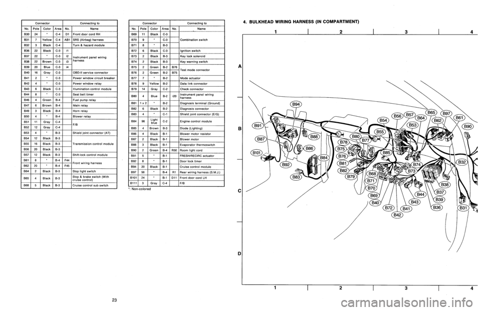
Connector
Connecting
to
No
.
Pole
Color
Area
No
.
Name
830
24
C-4
D1
Front
door
cord
RH
831
7
Yellow
C-4
A81
SRS
(Airbag)
harness
B32
3
Black
C-4
Turn
&
hazard
module
B36
22
Black
C-3
i1
B37
22
C-3
i2
Instrument
panel
wiring
B38
22
Brown
C-3
i3
harness
B39
20Blue
C-3
i4
B40
16
Gray
C-3
OBD-II
service
connector
B41
2
C-3
Power
window
circuit
breaker
842
4
C-3
Power
window
relay
B43
6
Black
C-3
Illumination
control
module
B44
8
C-3
Seat
belt
timer
B46
4
Green
B-4
Fuel
pump
relay
B47
6
Brown
B-4
Main
relay
B49
3
Black
B-4
Horn
relay
850
4
B-4
Blower
relay
851
11
Gray
C-4
FIB
B52
12
Gray
C-4
853
4
B-3
Shield
joint
connector
(AT)
B54
12
Black
B-3
B55
16
Black
B-3
Transmission
control
module
B56
20
Black
B-3
B57
12
Black
B-3
Shift-lock
control
module
861
B
B-4
F44
B62
20
B-4
F45
Front
wiring
harness
B64
2
Black
B-3
Stop
light
switch
B65
4
Black
B-3
Stop
&
brake
switch(Withcruise
control)
B68
5
i
Black
i
B-3
Cruise
control
sub
switch
Connector
Connecting
to
No
.
Pole
Color
Area
No
.
Name
B69
11
Black
C-3
B70
9
C-3
Combination
switch
B71
8
8-3
B72
6
Black
C-3
Ignition
switch
B73
2
Black
B-3
Key
lock
solenoid
B74
2
Black
B-3
Key
warning
switch
B75
2
Green
B-2
B76
B76
2
Green
&2
B75
Test
mode
connector
B77
7
B-2
Made
actuator
B78
9
Yellow
B-2
Data
link
connector
B79
14
Gray
C-2
Check
connector
B80
4
Blue
B-2
i20
Instrumentpanel
wiring
harness
B81
1
x
2
B-2
Diagnosis
terminal
(Ground)
B82
6
Black
B-2
Diagnosis
connector
B83
4
C-1
Shield
joint
connector
(E!G)
884
96
Light
blue
C-2
Engine
control
module
885
4
Brown
B-3
Diode
(Lighting)
B86
4
Black
B-1
Blower
motor
resistor
887
2
Black
B-1
Blower
motor
B88
3
Black
8-t
Evaporator
thermoswitch
890
2
Green
B-4
R50
Room
light
cord
B91
5B-1
FRESHIRECIRC
actuator
892
8
B-1
Door
lock
timer
B94
20
Black
B-1
Cruise
control
module
B97
56
B-4
R1Rear
wiring
harness
(S
.M
.J
.)
B101
24
B-1
D11
Front
doorcord
LH
13111
3
Gray
C-4
FIB
`
:
Non-colored
4
.
BULKHEAD
WIRING
HARNESS
(IN
COMPARTMENT)
A
B
C
1]
4
23
Page 209 of 2890
![SUBARU LEGACY 1996 Service Repair Manual 3-2
[rsPO]
AUTOMATIC
TRANSMISSION
AND
DIFFERENTIAL
8
.
Diagnostic
Chart
with
Select
Monitor
DISPLAY
LEDNo
.
Signal
name
Symbol
1
FWD
switch
FF
2
Kick-down
switch
KD
3
--
4
--
5
Brake
BR
6
ABS
SUBARU LEGACY 1996 Service Repair Manual 3-2
[rsPO]
AUTOMATIC
TRANSMISSION
AND
DIFFERENTIAL
8
.
Diagnostic
Chart
with
Select
Monitor
DISPLAY
LEDNo
.
Signal
name
Symbol
1
FWD
switch
FF
2
Kick-down
switch
KD
3
--
4
--
5
Brake
BR
6
ABS](/manual-img/17/57433/w960_57433-208.png)
3-2
[rsPO]
AUTOMATIC
TRANSMISSION
AND
DIFFERENTIAL
8
.
Diagnostic
Chart
with
Select
Monitor
DISPLAY
LEDNo
.
Signal
name
Symbol
1
FWD
switch
FF
2
Kick-down
switch
KD
3
--
4
--
5
Brake
BR
6
ABS
switch
AB
7
Cruise
control
set
CR
8
Power
switch
PW
9
-
-
10
t
-
--
I
-
FF
KDBR
ABCR
PW
DDDD
,o
DISPLAY
LEDNo
.
Signal
name
Symbol
1
N/P
range
switch
NP
2
R
range
switch
RR
3
D
range
switch
RD
43
range
switch
R3
5
2
range
switch
R2
6
1
range
switch
R1
7
Diagnosis
switch
SS
--
s
--
,o
_
1
-
NPRRRD
R3
R2
R1
SS
10
P
:
MODE
FAO
-
SWITCH
1
(SW1)
-
Reference
values
"
Lights
up
when
the
fuse
is
installed
in
FWD
switch
(No
.
1)
.
"
Lights
up
when
the
brake
pedal
is
depressed
(No
.
5)
"
Lights
up
when
the
ABS
signal
is
entered
(No
.
6)
.
"
Lights
up
when
the
cruise
control
is
set
(No
.
7)
.
NOTE
:
LED
Nos
.
2
and
8
do
not
come
on
.
Q
:
MODE
FA1
-
SWITCH
2
(SW2)
-
Reference
values
"
Lights
up
when
the
N
or
P
range
is
selected
(No
.
1)
.
"
Lights
up
when
the
R
range
is
selected
(No
.
2)
.
"
Lights
up
when
the
D
range
is
selected
(No
.
3)
.
"
Lights
up
when
the
3
range
is
selected
(No
.
4)
.
"
Lights
up
when
the
2
range
is
selected
(No
.
5)
.
"
Lights
up
when
the
1
range
is
selected
(No
.
6)
.
"
Lights
up
when
the
diagnosis
switch
is
connected
(No
.
7)
.
NOTE
:
If
each
LED
does
not
illuminate
in
the
above
conditions,
inhibitor
switch
malfunction
may
occur
.
Performdiagnos-
tics
on
inhibitor
switch
.
<
Ref
.
to
2-7
[T10AN0]
.*2
>
20
Page 268 of 2890

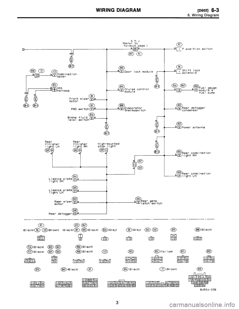
WIRING
DIAGRAM
[oso2i
6-3
6
.
Wiring
Diagram
GB-3
B3B
i3
i13
Comb
ination
'L~J
meter
B31
SRS
harness
BB
E
E
Frontwiper
[Uf
motor
4-6
GB-4
B9
FWD
sw
I
tch
CI
:~
816
Brakefluid
level
switch
Rear
Rear
finisherfinisher
light
LH
light
RH
049
8
D42
D4G
Lisence
plate
Iight
RH
D45
Lisence
plate
11ght
LH
043
Rearwipe
r
motor
048
Rear
defogge
r
R26
Rear
combination
LM
light
RH
R28
Rear
combination
LM
I(ght
LH
D46
Reargate
klatch
switch
R7
033R67
(B
I
ac
k)R6
i23
(BrowN
(B
I
ec
k)
B9
R25
(B
I
ec
k)
B16
(G
rey)
DB
(Gray)
D44045
21
2
12
1212
FI6
(B
I
ac
k)
B62D63R26
(B
I
ac
k)
039
12
BBB
(Black)
123
Fl7
(B
I
ac
k)
D49D42R2B
(B
I
ac
k)
(K)
(Y
e
11
ow)
(E)(9)
12
34
M1_2T3741
13141516
1
o23
N4
;5677
1
234
1
234
5
M67
8
R56
;7iR8
(B
I
8C
k)
(B
I
ac
K)
(Brown)
P
3141
56
789
1
F273
F1
4
6789
0151
7
89
1
2
34
161
2
314
0
1121314E
69
7181
1
11
1
12
1
314
51617
A
920
12
11112
314(51617
B4
02122
78
I
F1
34
161718
212223py
56
2~14
BUR04-03B
5
.
M
.
J
.
[Referto
foldout
page
.]
-
-
z~
B97
Rl
B92
Door
lock
module
B94
GB-8
Cruise
control
module
888
L=]
Evaporator
thermoswitch
R7
P
position
switch
R6
C
Shift
lock
solenoid
R46R67R58
Fuel
gauge
-e-C~umodule
&
fuel
pump
R25
LEE
Reardefogger
condenser
R23
-riPower
antenna
s1
-
~_5
GB-9
High-mounted
stop
light
D39
-12
m
R37
m4
D33
3
Page 275 of 2890
8
.
Electrical
Wiring
Harness
and
Ground
Point
Connector
Connecting
to
No
.
Pole
Color
Area
No
.
Name
R156
B-2
B97
Bulkhead
wiring
harness
(S
.M
.J
.)
R4
1
Black
B-2
Parking
brake
switch
R5
2B-2
Select
lever
illumination
light
R6
2
Black
B-2
Shift
lock
solenoid
R7
2B-2P
position
switch
RS
2B-2
Seat
belt
switch
R9
1
Brown
B-3Front
door
switch
LH
R11
8
B-4D21
Rear
doorcord
LH
R12
1
Brown
B-2
Front
door
switch
RH
R14
8
B-2
D27
Rear
door
cord
RH
R15
8B-3
R57
Fueltank
cord
R16
1
Brown
A-3
Rear
door
switch
RH
R30
2
Black
B-2
Diode
(Rear
gale
latch
switch)
R46
2
B3
R67
Fuel
lankcord
R50
2
Green
B-2
890
Bulkhead
wiring
harness
R52
2
A-3
Room
light
R57
S
B-3
R15
Rear
wiring
harness
R58
6
A-3
Fuel
gaugemodule
&
fuel
pump
R59
2
B-4
Fuel
gauge
submodule
R67
2
B-3
R46
Rear
wiring
harness
R68
2B-3
Pressure
control
solenoid
valve
R69
I
2
A-3
Vent
control
solenoid
valve
non-coiorea
A
B
C
n
6
.
REAR
WIRING
HARNESS
AND
GROUND
POINT
1
I
2
I
3
I
4
2
~S
4
[D806]
B6M0695A
A
B
C
u
Page 276 of 2890
8
.
Electrical
Wiring
Harness
and
Ground
Point
Connector
Connecting
to
No
.
Pole
Color
Area
No
.
Name
R156
B-2
B97
Bulkhead
wiring
harness
(S
.M
.J
.)
R4
1
Black
B-2
Parking
brake
switch
R5
2B-2
Select
lever
illumination
light
R6
2
Black
B-2
Shift
lock
solenoid
R7
2B-2P
position
switch
RS
2B-2
Seat
belt
switch
R9
1
Brown
B-3Front
door
switch
LH
R11
8
B-4D21
Rear
doorcord
LH
R12
1
Brown
B-2
Front
door
switch
RH
R14
8
B-2
D27
Rear
door
cord
RH
R15
8B-3
R57
Fueltank
cord
R16
1
Brown
A-3
Rear
door
switch
RH
R30
2
Black
B-2
Diode
(Rear
gale
latch
switch)
R46
2
B3
R67
Fuel
lankcord
R50
2
Green
B-2
890
Bulkhead
wiring
harness
R52
2
A-3
Room
light
R57
S
B-3
R15
Rear
wiring
harness
R58
6
A-3
Fuel
gaugemodule
&
fuel
pump
R59
2
B-4
Fuel
gauge
submodule
R67
2
B-3
R46
Rear
wiring
harness
R68
2B-3
Pressure
control
solenoid
valve
R69
I
2
A-3
Vent
control
solenoid
valve
non-coiorea
A
B
C
n
6
.
REAR
WIRING
HARNESS
AND
GROUND
POINT
1
I
2
I
3
I
4
2
~S
4
[D806]
B6M0695A
A
B
C
u
Page 879 of 2890
G3M0346
11) Remove the three accumulator springs.
G3M0347
12) Loosen the reverse clutch drum lightly by turning the
adjusting screw. Then remove the oil pump housing.
CAUTION:
Be careful not to lose the total end play adjusting
thrust washer.
G3M0348
13) Loosen the brake band adjusting screw with ST, and
take out the strut.
ST 398603610 SOCKET WRENCH
G3M0349
14) Remove the brake band and reverse clutch.
NOTE:
Contract the brake band with a clip.
G3M0350
15) Take out the high clutch.
CAUTION:
Thrust needle bearing and bearing race are removed
together with high clutch. Be careful not to lose them.
53
3-2SERVICE PROCEDURE
4. Overall Transmission
Page 960 of 2890

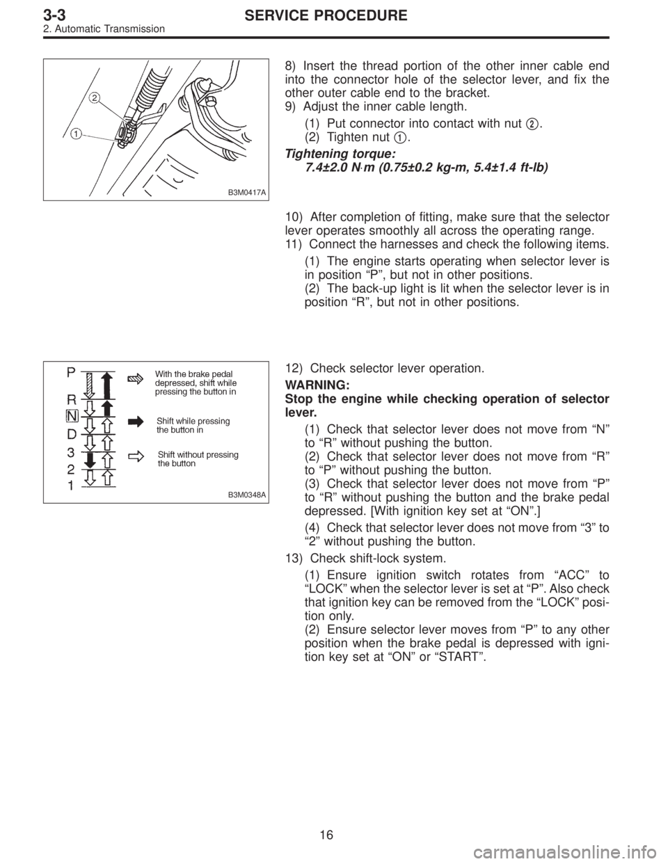
B3M0417A
8) Insert the thread portion of the other inner cable end
into the connector hole of the selector lever, and fix the
other outer cable end to the bracket.
9) Adjust the inner cable length.
(1) Put connector into contact with nut�
2.
(2) Tighten nut�
1.
Tightening torque:
7.4±2.0 N⋅m (0.75±0.2 kg-m, 5.4±1.4 ft-lb)
10) After completion of fitting, make sure that the selector
lever operates smoothly all across the operating range.
11) Connect the harnesses and check the following items.
(1) The engine starts operating when selector lever is
in position“P”, but not in other positions.
(2) The back-up light is lit when the selector lever is in
position“R”, but not in other positions.
B3M0348A
12) Check selector lever operation.
WARNING:
Stop the engine while checking operation of selector
lever.
(1) Check that selector lever does not move from“N”
to“R”without pushing the button.
(2) Check that selector lever does not move from“R”
to“P”without pushing the button.
(3) Check that selector lever does not move from“P”
to“R”without pushing the button and the brake pedal
depressed. [With ignition key set at“ON”.]
(4) Check that selector lever does not move from“3”to
“2”without pushing the button.
13) Check shift-lock system.
(1) Ensure ignition switch rotates from“ACC”to
“LOCK”when the selector lever is set at“P”. Also check
that ignition key can be removed from the“LOCK”posi-
tion only.
(2) Ensure selector lever moves from“P”to any other
position when the brake pedal is depressed with igni-
tion key set at“ON”or“START”.
16
3-3SERVICE PROCEDURE
2. Automatic Transmission
Page 1077 of 2890

Tightening torque:
186±20 N⋅m (19±2 kg-m, 137±14 ft-lb)
CAUTION:
�Use a new axle nut.
�Always tighten axle nut before installing wheel on
vehicle. If wheel is installed and comes in contact with
ground when axle nut is loose, wheel bearings may be
damaged.
�Be sure to tighten axle nut to specified torque. Do
not overtighten it as this may damage wheel bearing.
12) Install O-ring to hub cap flange, and install hub cap by
lightly tapping it with a plastic-faced hammer.
13) Install wheel and tighten wheel nuts to specified
torque.
Tightening torque (Wheel nut):
88±10 N⋅m (9±1 kg-m, 65±7 ft-lb)
4. Front and Rear Drive Shafts
A: REMOVAL
1. FRONT DRIVE SHAFT
1) Disconnect ground cable from battery.
2) Jack-up vehicle, support it with safety stands (rigid
racks), and remove front wheel cap and wheels.
3) Unlock axle nut.
4) While depressing brake pedal, remove axle nut using a
socket wrench.
CAUTION:
Be sure to loosen and retighten axle nut after remov-
ing wheel from vehicle. Failure to follow this rule may
damage wheel bearings.
5) Disconnect stabilizer link from transverse link.
6) Disconnect transverse link from housing.
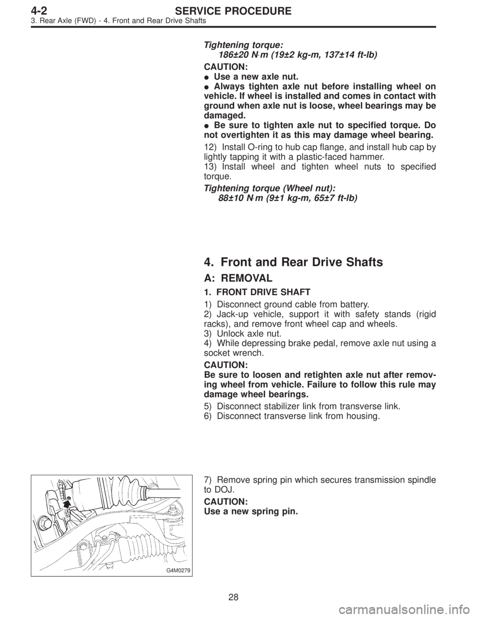
G4M0279
7) Remove spring pin which secures transmission spindle
to DOJ.
CAUTION:
Use a new spring pin.
28
4-2SERVICE PROCEDURE
3. Rear Axle (FWD) - 4. Front and Rear Drive Shafts