1996 HONDA CIVIC dcl
[x] Cancel search: dclPage 42 of 2189

Under-hood Emission Control Label (2000 model)
Emission Group ldentification
Example:
oRs'MM|LESt4,0oorml,wtscN
VEHICLE EMISSION CONTROL INFOBI\4ATIONT8ISVEH CLE CONFOfiMS TO U,S EPA RECIJLATIONSAPPLICABLE IO 'OOO MODEL YEAS NEW PASSENGER
CATALYST
vAtw LcsH rN 0.20:0 0? nnlcorDr EX 0 25:0 0? mhSPAAKPIIJGCAPNO OTNER AD.IUSIMENIS NE€OTO
t0N0a M0T08 (0. Lro
FEDERAL TIER 1:
THIS VEHICLE CONFORMS TO U,S. EPA REGULATIONSAPPLICABLE TO 2OOO MODEL YEAR NEW PASSENGERCARS.
CALIFORNIA + NLEV (RESTR|CTEDt TLEV:THIS VEHICLE CONFORMS TO CALIFORNIA REGULA-TIONS APPLICABLE TO 2OOO MODEL YEAR NEW TLEVPASSENGER CARS AND TO U,S. EPA NLEV PROGRAMREGULATIONS APPLICABLE TO 2OOO NEW TLEV PAS-SENGER CARS.
THIS VEHICLE MAY ONLY BE INTRODUCED INTO COM.MERCE FOR SALE IN CALIFORNIA. A STATE THAT HASTHE CALIFORNIA STANDARDS IN EFFECT TO WHICHTHIS VEHICLE HAS BEEN CERTIFIED, A STATE THATHAS OPTED INTO THE NLEV PROGRAM, OR A STATECONTIGUOUS THERETO.
50 STATE LEV + CFFV + NLEV {UNRESTRTCTED):THIS VEHICLE CONFORMS TO U.S, EPA NLEV ANDCLEAN.FUEL VEHICLE AND CALIFORNIA REGULA,TIONS APPLICABLE TO GASOLINE FUELED 2OOOMODEL YEAR NEW LEV PASSENGER CARS.EPA CERTIFICATION TEST FUEL: EPA UNLEADEDGASOLINE
50 STATE TLEV + NLEV (UNRESTRICTED}:
THIS VEHICLE CONFORMS TO U.S. EPA NLEV REGULA.TIONS APPLICABLE TO 2OOO MODEL YEAR NEW TLEVPASSENGER CARS AND CALIFORNIA REGULATIONSAPPLICABLE TO 2OOO MODEL YEAR NEW TLEV PAS-SENGER CARS.
n
1-40
L,
Engine and Evaporative Families
ro
Engine Family:Y HNX V 01,6 JF1
Model Yeal
Y; 2000
Manufaqturer
HNX: Honda
Type
V: Light Duty Vehicle/passenger CarDisplacoment
Sequence Charaqtgrs
Evaporative Family:Y HNX R OO99 AAD
Model Year
Y: 2000
Manufaeturer
HNX: Honda
Type
R: ORVR
Canister Work Capacity (grams)
Ssquence Characters
LO
Page 866 of 2189

Transmission
17.
Cooler Flushing (cont'dl
Make sure the transmission is in the E position.
Fill the transmission with ATF, and run the enginefor 30 seconds or until approximately 0.95 f (1.0 USqt.,0.8 lmp qt.) is discharged.
Remove the drain hose, and reconnect the coolerreturn hose to the transmission (see page l4-192).
Refill the transmission with ATF to the oroDer level(see page 14-118).
18.
19.
b
14-18A
TOOL MAINTENANCE
1. Empty and rinse after each use. Fill the can with waterand pressurize the can. Flush the discharge line toensure that the unit is clean.
2. lf discharge liquid does not foam, the orifice may beblocked.
3. To clean, disconnect the plumbing from the tank atthe large coupling nut.
ORIFICE
GRT{G
Remove the in-line filter from the discharge side andclean if necessary.
The fluid orifice is tocated behind the filter.Clean it with the pick stored in the bottom of thetank handle, or blow it clean with air. Securelvreassemble all Darts.
FILLER CAP
Page 1070 of 2189

Steering Gearbox
Installation (cont'dl
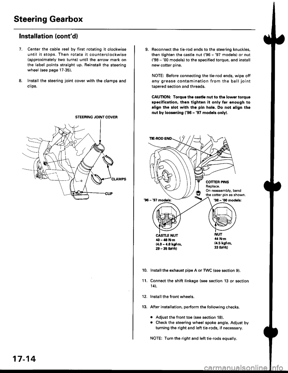
Center the cable reel by first rotating it clockwise
until it stops. Then rotate it counterclockwise(approximately two turns) until the arrow mark on
the label points straight up. Reinstall the steering
wheel (see page 17-35).
Install the steering joint cov€r with the clamps and
clrps.
7.
STEERING JOINI COVER
17-14
9. Reconnsct the ti€-rod ends to the steering knuckles,
thon tightsn th€ castle nut ('96 -'97 models) or nut('98 -'00 models) to the specified torque, and install
new cotter pins.
NOTE: Before connecting the tie-rod ends, wipe off
any grease contamination from the ball joint
tapered section and threads.
CAUTION: Torque lhe ct3tle nut to thr lowsr torque
spocification, th€n tighton it only tar anough to
align the 3lot with tho pin hob. Do not align the
nut by loosening ('96 - '97 modcls onlyl.
TIE.ROD
COTTER PINSR6plac6.On rgassombly, b6nd
'96 - 37 model3:
cotter prn as shown.'98 - '00 modol3:
NUT4a N.m(4.5 kgf.m,33 lbr.ftl
CAST1T NUT,O - ilt N'm{4,0 - 4.8 kgf.m.29 - 35 tbtftl
10.Installthe exhaust pipe A or TWC (see section 9).
Connect the shift linkage (see section 13 or section
14).
Install the front wheels.
After installation, perform the following checks.
. Adjust the front toe (see section 18).. Check the steering wheel spoke angle. Adjust by
turning the right and left tie-rods, if necessary.
NOTE: Turn the right and left tie-rods equally.
ll.
Page 1120 of 2189

Steering Gearbox
Reassembly (cont'dl
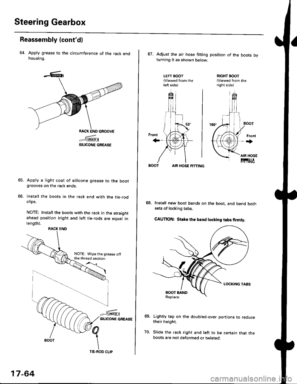
64. Apply grease to the circumference of the rack endhousing.
RACK END GROOVE
=^.#-q!:s!!H
SILICONE GREASE
Apply a light coat of silicone grease to the bootgrooves on the rack ends.
lnstall the boots in the rack end with the tie-rodclips.
NOTE: Install the boots with the rack in the straightahead position (right and left tie-rods are equal inlength).
66.
RACK END
NOTE: Wipe the grease offthe thread section.
17-64
TIE.ROD CLIP
67. Adjust the air hose fitting position of the boots bvturning it as shown below.
LEFT BOOT(Viewed from theleft side)
RIGHT BOOT{Viewed from theright side)
AIR HOSE FITTING
Install new boot bands on the boot, and bend bothsets of locking tabs.
CAUTION: Stlke ths band locking tabs firmly.
Lightly tap on the doubled-over portions to reducetheir height.
Slide the rack right and left to be certain that theboots are not deformed or twisted.
Page 1276 of 2189

Ouarter Glass
1.
Installation
Using a knife, scrape the old adhesive smooth to athickness of about 2 mm (0.08 in.) on the bondingsurface around the entire quarter glass openingflange.
NOTE:
. Do not scrape down to the painted surface of thebody; damaged paint will interfere with proper
a
a
bonding.
Remove the fastener from the body.lf any of the clips are broken, remove lhem fromthe body.
Mask off surrounding surfaces before applyingpnmer.
Clean the body bonding surface with a sponge dampened in alcohol.
NOTE: After cleaning, keep oil, grease and waterfrom getting on the surface.
lf the quarter glass is to be reinstalled, use a puttyknife to scrape off all traces of old adhesive. thenclean the quarter glass surface with alcohol whereadhesive is to be applied.
NOTE: Make sure the bonding surface is kept freeof water. oil and grease.
CAUTION: Avoid setting the quarter glass on itsodges; small chips may later develop into cracks,
NOTE: Clean the shadowed area.
20-46
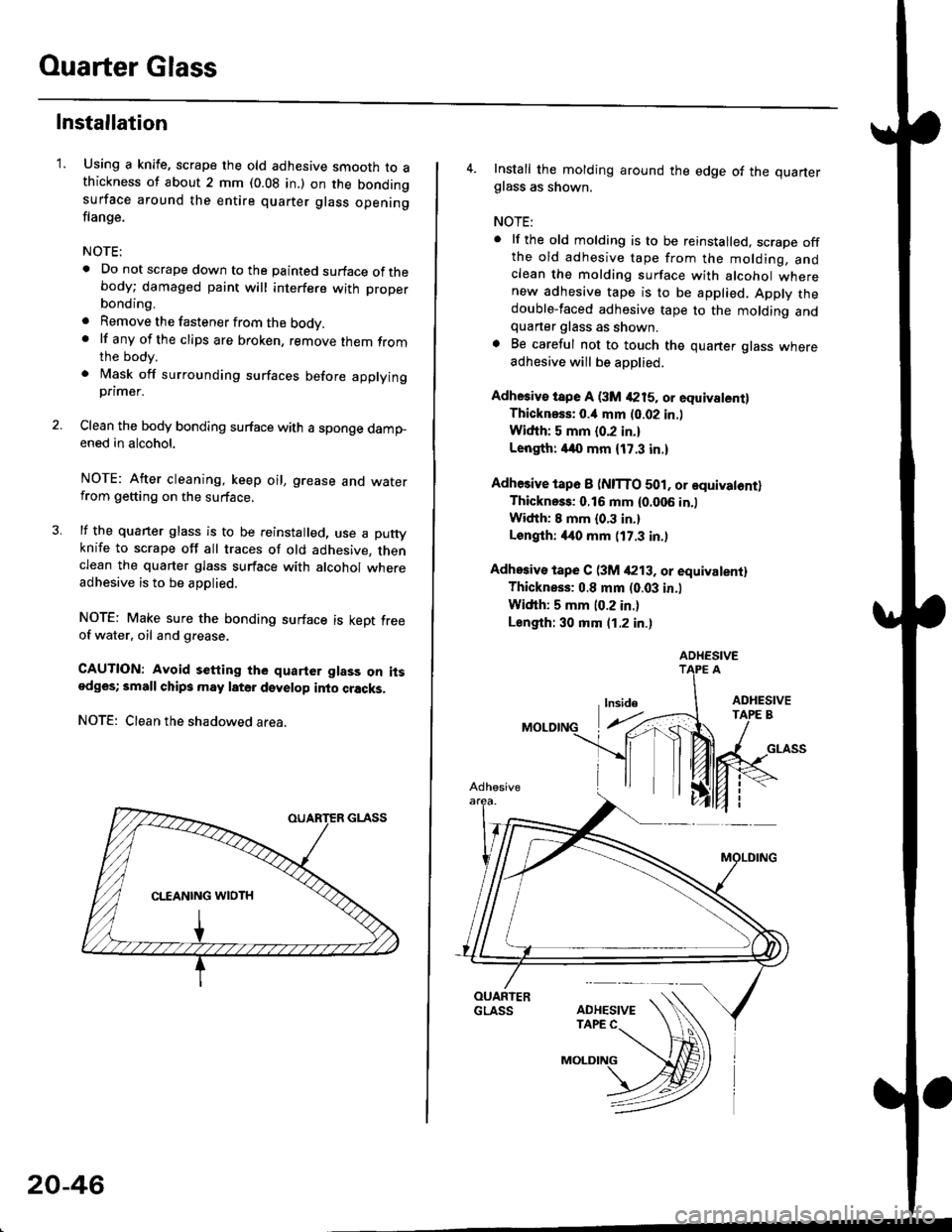
4. Install the molding around the edge of the quarterglass as shown.
NOTE:
. lf the old molding is to be reinstalled, scrape offthe old adhesive tape from the molding, andclean the molding surface with alcohol wherenew adhesive tape is to be applied. Apply thedouble-faced adhesive tape to the molding andquarter glass as shown.. Be careful not to touch the quarter glass whereadhesive will be aoDlied.
Adhesiv€ tspe A (3M 4215, or equivalent)Thicknsss: o.il mm (0.02 in.l
Widih: 5 mm {0.2 in.}
Length: /140 mm {17.3 in.)
Adhesive tap6 I (NITTO 501, or equivatontlThickness: 0.16 mm {0.006 in.)
Width: I mm {0.3 in.}
Longlh: 4it0 mm (17.3 in.)
Adhosiv€ tape C (3M /P13. or equivalentl
Thickness: 0.8 mm (0.03 in.l
Width: 5 mm (0.2 in.)
Length: 30 mm (1.2 in.)
ADHESIVE
Page 2136 of 2189

\I
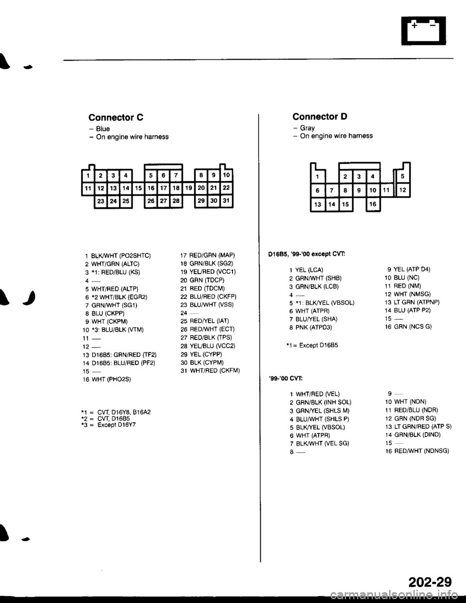
Connector C
- Blue- On engine wire harness
1 BLK/WHT (PO2SHTC)
2 WHT/GRN (ALTC)
3 al: RED/BLU (KS)
5 WHT/RED (ALTP)
6 12 WHT/BLK (EGR2)
7 GRNAVHT (SGl)
8 BLU (CKPP)
9 WHT (CKPM)
10 *3: BLU/BLK (VTM)
13 D1685: GRN/RED OF2)14 01685: BLU/RED (PF2)
16 WHT (PHO2S)
17 RED/GRN (MAP)
18 GRN/BLK (SG2)
1s YEURED (VCC1)
20 GRN (TDCP)
21 RED fiDcl\4)22 BLU/RED (CKFP)
23 BLU,ryVHT (VSS)
24
25 RED/yEL (lAT)
26 REDAVHT (ECT)
27 RED/BLK (TPS)
28 YEUBLU (VCC2)
29 YEL (CYPP)
30 BLK (CYPr,,t)
31 WHTiRED (CKFrVr)
cw D16Y8,816A2cw D1685Except D l6Y7
t
1sl't0234678
111213141516171819202122
23242526272A293031
Connector D
- Gray- On engine wire harness
D1685, '99100 except CW:
1 YEL (LCA)
2 GRN,ryVHT (SHB)
3 GRN/BLK (LCB)
5 .1 : BLIVYEL (VBSOL)
6 WHT (ATPR)
7 BLU/YEL {SHA)8 PNK (ATPD3)
*1= Except D1685
'99100 cw:
1 WHT/RED (VEL)
2 GRN/BLK (rNH SOL)
3 GRN/vEL (SHLS l\4)
4 BLUAVHT (SHLS P)
5 BLK^fEL (VBSOL)
6 WHT (ATPR)
7 BLKWHT (VEL SG)
8
9 YEL (ATP D4)
10 BLU (NC)
11 RED (Ntvl)
12 WHT (NMSG)
13 LT GRN (ATPNP)
14 8LU {ATP P2)
16 GRN (NCS G)
I
1O WHT (NDN)
11 RED/BLU (NDR)
12 GRN (NDR SG)
13 LT GRN/RED (ATP S)
14 GRN/BLK (DIND)
16 REDMHT (NDNSG)
IJ
14
6o10rr ll rz
13141516
202-29