1996 HONDA CIVIC Ftp sensor
[x] Cancel search: Ftp sensorPage 272 of 2189
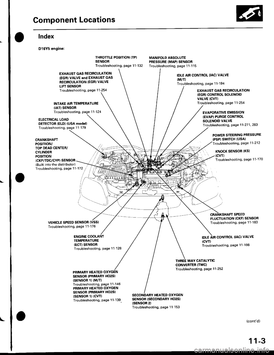
Gomponent Locations
L
lndex
D16Y5 engine:
{IATISENSORTroubleshooting,
ELECTRICAL LOADDETECTOR IELD) (USA mod6l)Troubleshooting, page 11 179
THROTTLE POSITION ITP)SENSORTroubleshooting, page 1 1-132
MANIFOLD ABSOLUTEPRESSURE IMAPI SENSORTroubleshooting, page 1'l-115
EXHAUST GAS RECIRCULATION
IEGRI VALVE and EXHAUST GAS
RECIRCULATION IEGRI VALVE
LIFT SENSORTroubleshooting, page'l 1-254
INTAKE AIR TEMPERATUR€
IDLE AIR CONTROL (IAC) VALVE
{M/T)Troubleshooting, page 1 1-194
EXHAUST GAS RECIRCULATION{EGRI CONTROL SOLENOIDVALVE ICW)Troubleshooting. page 1 1-254
EVAPORATIVE EMISSIONIEVAPI PUNGE CONTROLSOLENOID VALVETroubf eshooting, Page 1 1'21 1, 243
CRANKSHAFTPOS|TTON/TOP DEAD CENTER/CYLINDERPOS|T|ON
POWER STEERING PRESSURE(PSP) SWITCH (USAI
Troubleshooting, Page 1 1-212
KNoCK SENSoR (Ks)
(cwl
Troubleshooting, Page 1 1'170ICKP/TDC/CYP} SENSOR(Built into the distributor)Troubleshooting, Page 1 1'172
VEHICLE SPEED SENSORTroubleshooting, Page 1 1-176
FLUCTUATION (CKF} SENSOR
Troubleshooting, Page 1 1 -183
ENGINE COOLANTTEMPERATUREIECT) SENSORTroubleshooting, Page 11 128
IDT.ECONTROL IIACI VALVE
{cw)Troubleshooting, Page 11 198
WAY CATALYTICCONVERTER ITWCITroubleshooting, Page 1 1-252PRIMARY TIEATEDSENSOR {PNIMARY HO2SI
tsENsoR 1t {M/TlTroubleshooting, Page'l 1-146
PRIMARY HEATED OXYGENSENSOR (PRIMARY HO2SI
tsENsoR 1l {cw}Troubleshooting, Page 1 1-139
SECONDARY HEATED OXYGENSENSOR {SECONDARY HO2S){SENSOR 2)Troubleshooting, page 11 153
(cont'd)
1 1-3
Page 273 of 2189
Component Locations
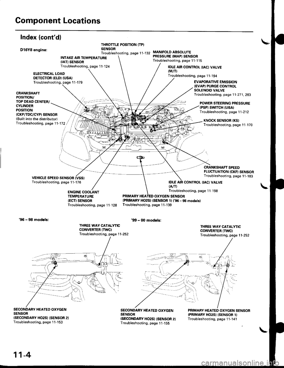
Index (cont'd)
D16Y8 enginc:
THROTTLE POSITION {TPISENSORTroubleshooting, page 1 1-132
ELECTRICAL LOADDETECTOR IELDI {USAI
INTAKE AIR TEMPERATUREIIATISENSORTroubleshooting, page 1 1,124
MANIFOLO ABSOLUTEPRESSURE {MAPI SENSORTroubleshooting, page 1 1-1 15
IDI.E{A/T)
IDI.E AIR CONTROL IIACI VALVElMtflTroubleshooting, page 1 1-194
Troubleshooting, page 1 1-179EVAPORATIVE EMISSIONIEVAPI PURGE CONTROLSOLENOIO VALVETroubleshooting, page 1 1 27 1. 283CRANKSHAFTPOSTTTON/TOP DEAD CENTER/CYLINDERPOStTtON
POWER STEERING PRESSURE(PSPI SWTTCH |USA)Troubleshooting, page 1 1-212{CKP/TI'C/CYPI SENSOR(Built into the distributor)Troubleshooting. page 1 1-172KNOCK SENSOR IKSITroubleshooting, page 11 170
CRANKSHAFT SPEEDFLUCTUANON ICKFI SENSORTroubleshooting, page 1 1,183
CONTROL {IACI VALVE
ENGINE COOLANTTEMPERATURE{ECTI SENSORTroubleshooting, page 11 128
Troubleshooting, page 11 198
PRIMARY HEATED OXYGEN SENSOR{PRIMARY HO2S} (SENSOR 1l {'96 - 98 modolslTroubleshooting, page 1 1-139
'9!t - 00 modols:'96 - 98 modols:
THREE WAY CATALYNCCONVERTER ITWCITroubl6shooting, page 1 1-252
THREE WAY CATALYNCCONVERTER ITWCITroubleshooting. page 1 1-252
SECONDARY HEATED OXYGENSENSOn(SECONDARY HO2SI (SENSOR 2ITroubleshooting, page 1 1-153
SECONDARY HEATED OXYGENSENSOBISECONDARY HO2S} ISENSOR 2ITroubloshooting, page 1 1-155
PRIMARY HEATEO OXYGEN SENSORIPRIMARY HO2SI ISENSOR 1ITroubleshooting, page 1 1-141
11-4
Page 274 of 2189
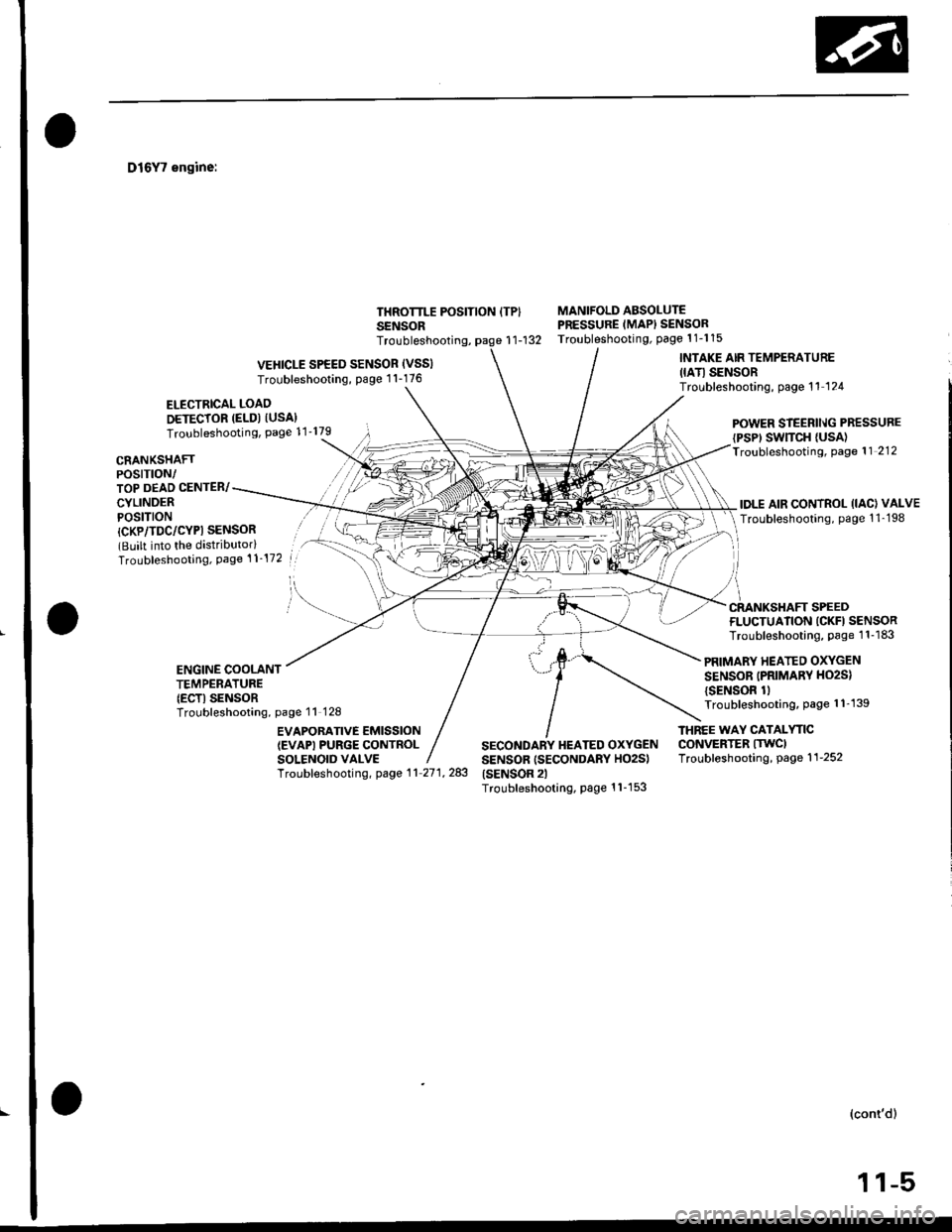
D16Y7 engine:
ELECTRICAL LOAO
DETECTOR (ELD) IUSA}Troubleshooting, Page 11'179
THROTTLE POSITION ITPISENSOR
MANIFOLD ABSOLUTEPRESSURE (MAPI SENSORTroubleshooting, Page 1 1-1 15r1-132
CRANKSHAFTPOSTTTON/TOP DEAD CENTER/
CYLINDERPOSITION
POWER STEERll\lG PRESSURE
{PSP' SWTTCH {USA)Troubleshooting, Page 11 212
IDLE AIR CONTROL (IAC) VALVE
Troubleshooting, page 1 1-198
Troubleshooting,
VEHICLE SPEED SENSOR (VSSI
Troubleshooting, Page 1 1-176
INTAKE AIR TEMPERATURE
IIATI SENSORTroubleshooting, page 11 124
l
/i
CRANKSHAFT SPEED
{CKP/TDC/CYPI SENSOR(Built into the distributorlTroubleshooting, Page 't 1-172
FLUCTUATION ICKFI SENSORTroubleshooting, Page 1 1-183
PRIMARY HEATED OXYGEN
SENSOR (PRIMARV HO2S)
{SENSOR 1lTroubleshooting, page 1 1'139
ENGINE COOLANTTEMPERATURE(ECTI SENSORTroubleshooting, page 11 128
EVAPOBATIVE EMISSION(EVAPI PURGE CONTROLSOLENOID VALVE
THNEE WAY CATALYTICCONVERTER ITWCITroubleshooting, page 1 1-252
Troubf eshooting, page 1 1 27 1, 283
SECONDARY HEATED OXYGENSENSOR (SECONDARY HO2S)(SENSOR 2lTroubleshooting, Page 1 1-1 53
(cont'd)
,l .ltr| | -r,
Page 441 of 2189

PGM-FI System
tFos3sl
tFffi6l
tPr361 I
fPfi62l
fFr38il
tF13s2-l
Crankshaft Position/Top Dead Genter/Gylinder Position (CKP/TDC/CYP) Sensor
('96 - 98 Models, '!n - 00 D16Y5 engine with M/Tl
The scan tool indicates Diagnostic Trouble Code (DTC) P0335: A malfunction in the Crankshaft position (CKp)
sensor circuit.
The scan tool indicates Diagnostic Trouble Code (DTC) P0336: A range/performance problem in the CrankshaftPosition (CKP) sensor circuit.
The scan tool indicates Diagnostic Trouble Code (DTC) P1361: Intermittent interruotion in the Too Dead Center(TDC) sensor circuit.
The scan tool indicates Diagnostic Trouble Code {DTC) P1362: No signal in the Top Dead Center (TDC} sensorcircuit.
The scan tool indicates Diagnostic Trouble Code (DTC) P1381: Intermittent interruption in the Cvlinder Position{CYP) sensor circuit.
The scan tool indicates Diagnostic Trouble Code {DTC) Pl382: No signal in the Cylinder Position (CYP} sensorcircuit.
Description
The CKP Sensor determines timing for fuel injection and ignition of each cylinder and also detects engine speed. The TDCSensor determines ignition timing at start-up (cranking) and when crank angle is abnormal. The Cyp Sensor detects theposition of No. 1 cylinder for sequential fuel injection to each cylinder. The CKP/TDC/CYP Sensor is built into the distribu-ror.
NOTE: lf DTC P1359 is stored atthesametime as DTC P0335. P0336, P1361, Pl362, P1381 and/or P1382, troubteshoor DTCP1359 first, then recheck for those DTCS. Ot6y5 6ngine: Dt6y7, ot6y8 enqin6s:
SENSORBOTOR
TDCSENSORCKPSENSORSENSORROTORSENSORROTORSENSORROTORROTORROTOR
DISTRIBUTOR 1OPcoNNECTOR tC120tTDC P
- The MIL hrs been reported on.- DTC P0335, P0336, P1361,P1362, P1381 and/or Pl382 6restored,
Problem verification:1. Do the ECM/PCM Reset Proce-dure.2. Stan the engine.
Intermittent hilu.e, system b OKat this time. Check tor poor con-n€ctions or 10036 wiros at C120{distributor} and ECM/PCM.
ls DTC P0335, P0336, P1361, P1362,P1381 and/or P'l382 indicated?
Check for an open in the CKP/TDC/CYP sensor:1. Turn the ignition switch OFF.2. Disconnect the distributor 10P
3. Measure resistance betweenthe terminals of the indicatedsensor (*see table).
Replace the distributor ignitionhousing (soe section 23).ls there 350 - 700 0?
CYP M {BLK}
SENSORDTCSENSORIERMINATECMfCMTERMINATCOLOR
CKPP033s
m336
2c2BLU
6c12
TDCP1361
P1362
3GRN
7cl3RED
CYPP!381
P't382
c4YEL
8c148LK11-172
Page 456 of 2189
l,a
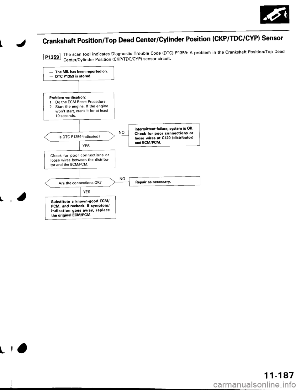
Crankshaft Position/Top Dead Center/Cylinder Position (CKP/TDC/CYPI Sensor
Thescantoo|indicatesDiagnosticTroub|ecode(DTc)P1359:Aprob|eminthecrankshaftPosjtion/TopDead
Center/Cvlinder Position (CKP/TDC/CYP) sensor circuit'
- The MIL has been reported on- DTC P1359 is stored
Problem veritication:1. Do the ECM Reset Procedure
2. Stan the engine lftheengine
won't start, crank it for at least
10 seconds-
lntermittent failure, sYstem is OK
Check for poor connecllon3 or
loose wires at C120 {distributor}and ECM,/PCM.
ls DTC P1359 indicated?
Check for poor connections or
loose wires between the distribu
tor and the ECM/PCM
Substitute a known'good ECM/
PCM, and rccheck. lt 3ymPtom/
indication goes awtY, rePlace
the original ECM/PCM.
r ta
11-1A7
Page 543 of 2189
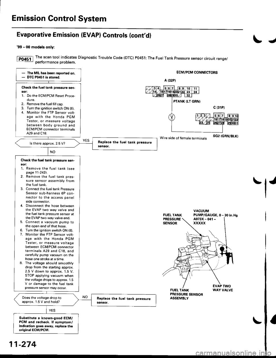
Emission Control System
Evaporative Emission (EVAP) Gontrols (cont'd)
'99 - 0O models only:
The scan tool indicates Diagnostic Trouble Code (DTC) P0451: The Fuel Tank Pressure sensor circuit range/oerformance Droblem.
ECM/PCM CONNECTORS
wire side ot femare terminars sG2 IGRN/BLK)
FUEL TANKPRESSURESENSOR
VACUUMPUMP/GAUGE,0 - 30 in.Hg
FUEL TANKPRESSURE SENSORASSEMBLY
EVAP TWOWAY VALVE
IJ
tl'
Ths MIL has been reDortgd on.DTC m/$1 i3 stored.
Check the tuel tank pros3ure ser|-sor:1. Do the ECM/PCM Reset Proce-dure.2. Remove the tuellill cap.3. Turn the ignition switch ON (ll).4. N4onitor the FTP Sensor volt-age with the Honda PGMTester, or measure voltagebetween body ground andECN4/PCM connector terminalsA29 and C18.
ls there approx. 2.5 V7
Check tho tuel tank pressure !on-soa:1. Remove the fuel tank (seepage 11 2421.2. Remove the fuel tank pres-sure sensor assembly fromthe fueltank.3. Connect the fuel tank PressureSensor sub-harness 6P con-nector to the access panelside connector,4. Disconnect the hose betweenthe EVAP two way valvg andthe fuel tank pressure sensor atthe EVAP two way valve end.5. Connect a vacuum pump tothe open end ofthat hose.6. Turn the ignition switch ON (ll).7. Monitor the FTP Sensor volt,age with the Honda PGMTester, or measure voltagebetween ECM/PCM connectorterminals A29 and C18, andcarefully pump vacuum on thehose one stroke at a time.8. The voltage sho!ld smoothlydrop from the stading approx.2.5 V down to approx. '1.5 V.STOP applying vacuum whenthe voltage drops to approx. 1.5V or damage to the fuel tankpressure sensor may occur.
Does the voltage drop toapprox. 1.5 V and hold?
Sub3titute a known-good ECM/PCM and r6check. It symptom/indicltion 90e3 aw.y, replac\. th€original ECM/PCM.
A (32P)
A973X - 041 -
xxxxx
11-274
Page 544 of 2189

\J
Fuel Tank Pro3sure sensor 196 D16Y8 engine (coupe).'97 D15Y7 engine {coupe: KL model, sedan: KL (LX) modeu,'97
D16Y8 engine (coupe: all models, sedan: KL model, '98-all models) '99 - 00 D16Y5 engine with M/Tl:
\
PTANK
{LT GRNI
vcc2(YEL/BLU}
Wire side oI female terminals
FUEL TANKPRESSURE SENSOR3P CONNECTOR (C7921
sG2IGRN/8LK)
Foc2l::il":"toolindicatesDiagnosticTroublecode(DTc)P0452:A|owvo|tageprob|emintheFue|TankPressure
The fuel tank pressure sensor converts fuel tank absolute pressure into electrical signals and inputs the EcM/PCM.
OUTPUTVOLTAGEtvt4.5
-? kPa(-50 mmHg,-2 in.Hg)
ECM/PCM CONNECTOR O I16P)
Wire side of female terminals
+7 kPs150 mmHg,2 in.Hg)
PRESSURE
(cont'd)
11-275
- The MIL has been reported on- DTC P0452 is stored.
Check the vacuum lines:
Check the vacuum lines of the
fuel tank pressure sensor for mis-
routing, leakage, breakage and
cloggrng.
Are the vacuum lines OK?
Problem v€ritication:1. Do the ECM/PCM Reset Proce
dure.2. Remove the luel fill caP.
3. Turn the ignition switch ON lll)4. Monitor the FTP Sensor volt_
age with the Honda PGM
Tester, or measure voltage
between bodY ground and
ECM/PCM terminal Dl5.lntermittent tailuro, sYstem i5 OK
dt this timo. Chock for Poot con-
neciion3 or loose wir* at C131
llocatod under right side ot dashl,
C4O1 (located .bove under'da3htuso/ielay box), C574 1C568)*
{located under acc€ss Panell.C792 lfuel tank pressule sen3or)
and EcM/PCM.
ls there approx. 2.5 V?
Check tol an op€n in wite (VCC2
line):1. Turn the ignition switch OFF
2. Reinstallthe fuel fill caP.3. Disconnect the fuel tank Pres'sure sensor 3P connector-4. Turn the ignition switch ON (ll)
5, Measure voltage between the
fuel tank pressure sensor 3P
connector No. l terminal and
No. 2 terminal.
Repair open in the wite betweenthe fuel tank Pr€s3ure a€n3or andth6 EcM/PcM (D1ol.ls there approx. 5 V?
(To page 11'276)
Page 546 of 2189

\
'99 - 00 models excepi Dl6Y5 engine with M/T:
The scan tool indicates Diagnostic Trouble Code (DTC) P0452: A low voltage problem in the Fuel Tank Pressure
sensor.
The fuel tank pressure sensor converts fuel tank absolute pressure into electrical signals and inputs the ECM/PCM
OUTPUTVOLTAGE(vlt.5
0.5-7 kP.(-g) mmHg,-2 in.Hgl
+7 kP.
150 mmHg,2 in.Hgl
PRESSURE
I
Wire side of lemale terminals
FUEL TANKPRESSURE SENSORSUB.HARNESS6P CONNECTOR (C574 (C568)rl
vcc2(YEL/BLUIsG2{GRN/BLK}
Wire side o{ temale terminals
The MIL has been .eported on.
DTC P0452 is stored
Check the vacuum lines:
Check the vacuum lines of the
fuel tank pressure sensor lor mis-
routing, leakage, breakage and
cloggrng.
Are the vacuum hnes OK?
Problem veritication:1. Do the ECM/PCM Reset Proce-
du re,2. Bemove the fuel fill caP.
3. Turn the ignition switch ON {ll)
4. Monitorthe FTP Sensor voltage
with the Honda PGM Tester' or
measure voltage between body
groLrnd and ECM/PCM connec_
tor terminalA29.
lntermitlent tailure, 3Ystem b OK
at this time. Check for Poor con'
nections or loose wire3 at C131
{located under right side of dash},
C401 {located above under'dash
tuse/relay box), C574 (C568)*
llocdted under access Panel),C792 (tuel rank Prcssure sensorl
and ECM/PCM.
ls there approx.2 5 V?
Check for an open in wire {VCC2
line):1. Turn the ignition switch OFF.
2. Reinstall the ltrel fill caP
3, Remove the access Panel from
the floor.4. Disconnect the fuel tank Pres'sure sensor sub-harness 6P
5. Turn the ignition switch ON (ll).
6. At the access Panel side, mea_
sure voltage between the fuel
tank Pressure sensor sub-nar-
ness 6P connector No 5termi
nal and No. 6 termlnal.
Repair open in tho wire between
th6 fu€l tank Prossuro sen3oa and
the ECM/PCM lc28).ls there approx 5 V?
ECM/PCM CONNECTOR A (32P)
PTANK {LT BLUI
I
ll
(To page '11-278)
(cont'd)