1996 HONDA CIVIC Cowl
[x] Cancel search: CowlPage 506 of 2189
I
PGM-FlMain Relay
Description
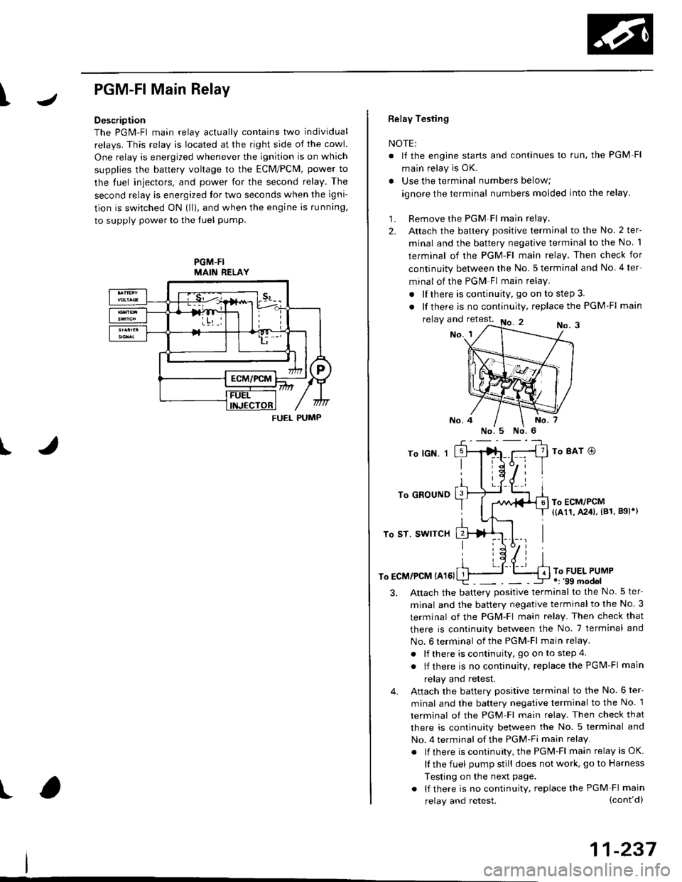
The PGM-Fl main relav actuallv contains two individual
relays. This relay is located at the right side of the cowl.
One relay is energized whenever the ignition is on which
supplies the battery voltage to the ECM/PCM, power to
the luel iniectors, and power for the second relay. The
second relay is energized lor two seconds when the igni-
tion is switched ON (lll, and when the engine is running,
to supply power to the luel pump.
PGM-FIMAIN RELAY
J
I
t
FUEL PUMP
Relay Testing
NOTE:
. It the engine starts and continues lo run. the PGM Fl
main relay is OK.
. Use the terminal numbers below;
ignore the terminal numbers molded into the relay,
1. Remove the PGM Fl main relay.
2. Attach the battery positive terminal to the No. 2 ter-
minal and the battery negative terminal to the No 1
terminal of the PGM-Fl main relay. Then check for
continuity between the No.5 terminal and No 4ter-
minal of the PGM Fl main relay.
. lf there is continuity, go on to step 3.
. lf there is nocontinuity, replacethe PGM-Fl main
relay and retest.No. 3No. 1
To lGN. 1
To GROUND
To ST. SWITCH
To ECM/PCM {A161
To 8AT O
To ECM/PCM{(a11, A241, (81. B9l*l
To FUEL PUMP.r '99 model
3.Altach the batterv positive terminal to the No.5 ter-
minal and the battery negative terminal to the No. 3
terminal of the PGM-Fl main relay. Then check that
there is continuity between the No. 7 terminal and
No. 6 terminal of the PGM-Fl main relay.
. lf there is continuity, go on to step 4
. lf there is nocontinuity, replacethePGM-Fl main
relay and retest.
Attach the battery positive terminal to the No. 6 ter-
minal and the battery negative terminal to the No. 1
terminal of the PGM Fl main relay. Then check that
there is continuity between the No. 5 terminal and
No. 4 terminal of the PGM-Fi main relay.
. lf there is continuity, the PGM-Fl main relay is OK.
lf the fuel pump still does not work, go to Harness
Testing on the next page.
. lf there is no continuity, replace the PGM Fl main
4.
(cont'd)
11-237
relay and retest.
Page 1258 of 2189
Windshield
Removal
CAUTION:
. Put on gloves to plotest your h8nds.
. Use seat covers to avoid damaging any surfaces.
1. To remove the windshield, first remove the:. Rearview mirror (see page 20-25)
. Sunvisors and holders (see page 20-64)
. Front pillar trim (see pages 20-59, 60, 61)
! Windshield wiper arms and cowl cover (see page
20-1131
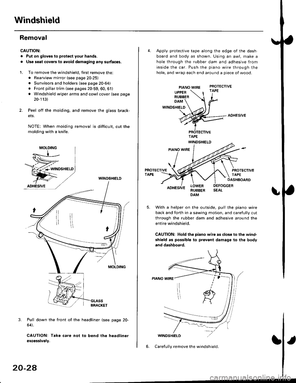
Peel off the molding, and remove the glass brack-
ers.
NOTE: When molding removal is difficult, cut the
molding with a knife.
WINDSHIELO
3. Pull down the front of the headliner (see page 20-
64).
CAUTION: Take care not to bend the headlinet
excsssively.
MOLDING
20-24
4. Apply protective tape along the edge of the dash
board and body as shown. Using an awl, make a
hole through the rubber dam and adhesive from
inside the car. Push the piano wire through the
hole, and wrap each end around a piece of wood-
PIANO WIREPROTECTIVE
UPPERRUBBER| '1"
DAM
WINDSHIELO
AOHESIVE
RUBBERDAM
With a helper on the outside, pull the piano wire
back and forth in a sawing motion, and carefully cut
through the rubber dam and adhesive around the
entire windshield.
CAUTION: Hold the piano wile as close to ihe wind-
shield as possible to prevent damage to the body
and dashboard.
WINDSHIELD
6. Carefully remove the windshield.
Page 1261 of 2189
3
11.Thoroughly mix the adhesive and hardener together
on a glass or metal plate with a putty knife.
NOTE:
. Clean the plate with a sponge and alcohol before
mixing.
. Follow the instructions that come with the adhe-
stve.
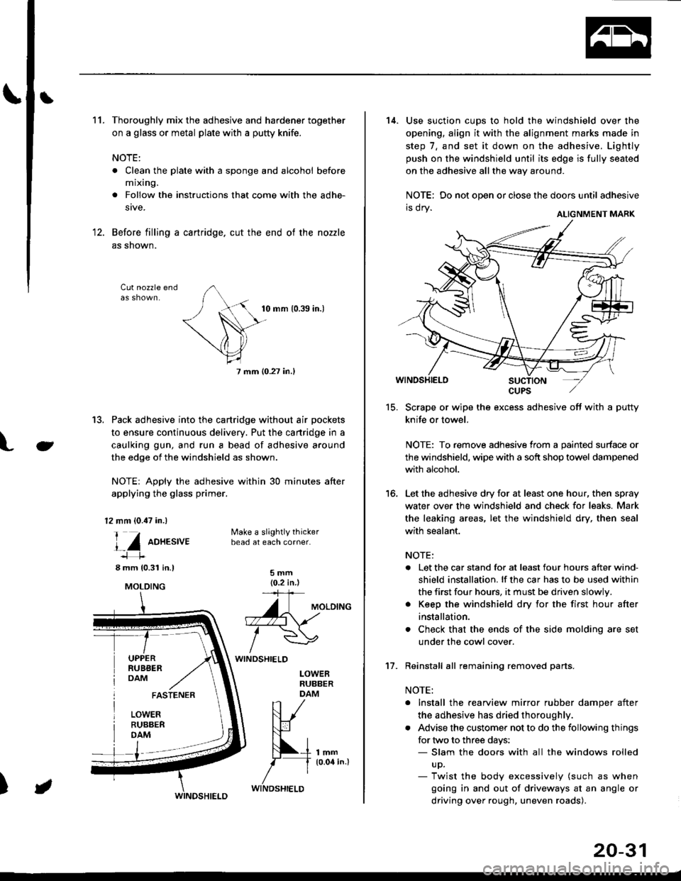
Before filling a cartridge. cut the end of the nozzle
as shown.
Cut nozzle end
tu
10 mm 10.39 in.)
7 mm (0.27 in.l
13. Pack adhesive into the cartridge without air pockets
to ensure continuous delivery. Put the cartridge in a
caulking gun, and run a bead of adhesive around
the edge of the windshield as shown.
NOTE: Apply the adhesive within 30 minutes after
applying the glass primer.
12 mm (0.47 in.)
l_Z oo*.t,ut
8 mm 10.31 in.l
UPPERRUBBERDAM
Make a slightly thickerbead at each corner.
5mm(0.2 in )='+
A\uloto^o. -.\
/wWINDSHIELD
LOWEBRUBBERDAM
lmm10.04 in.l
FASTENER
LOWERRUBBERDAM
)
MOLDING
WINDSHIELD
20-31
15.
16.
14. Use suction cups to hold the windshield over the
opening, align it with the alignment marks made in
step 7, and set it down on the adhesive. Lightly
push on the windshield until its edge is fully seated
on the adhesive all the way around.
NOTE: Do not open or close the doors until adhesive
ri vI Y ALTGNMENT MARK
Scrape or wipe the excess adhesive off with a putty
knife or towel.
NOTE: To remove adhesive from a painted surface or
the windshield, wipe with a soft shop towel dampened
with alcohol.
Let the adhesive dry for at least one hour, then spray
water over the windshield and check for leaks. Mark
the leaking areas, let the windshield dry, then seal
with sealant.
NOTE:
. Let the car stand for at least four hours after wind-
shield installation. lf the car has to be used within
the first four hours, it must be driven slowly.
. Keep the windshield dry for the first hour after
installation.
. Check that the ends of the side molding are set
under the cowl cover.
Reinstall all remaining removed parts.
NOTE:
. Install the rearview mirror rubber damper after
the adhesive has dried thoroughl',.
. Advise the customer not to do the following things
for two to three days:- Slam the doors with all the windows rolled
up.- Twist the body excessively (such as when
going in and out of driveways at an angle or
driving over rough, uneven roads).
't7.
Page 1343 of 2189
Windshield Wiper Arms
and Linkage
Hatch latch/Lock cylinder:
NOTE: Remove the hatch trim panel (see page 20-63).
>: Bolt locationsA>,3
6x1.0mm I9.8 N.m i1.0 ksf m,l
1.2lbl.trl /
B>, 1
E6'cr
CYLINDER
6;:il;l,lr'.",
.r\
LOCK- r€ cYLTNDERL^ ! ./
rAs<.L ,/
\faa"El
rl
lnstallation is the reverse of the removal procedure.
NOTE:
. Grease the hatch latch.
. Make sure the hatch opens properly and locks
securely.
. Make sure the cylinder rod is connected properly.
Replacement
CAUTION: Pul on gloves to protect your hands
NOTE: Take care not to scratch the hood and body.
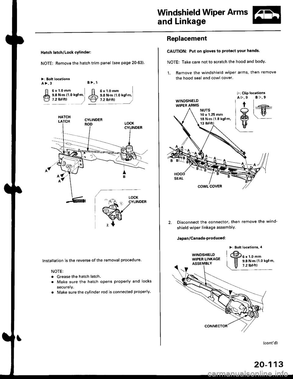
1. Remove the windshield wiper arms, then remove
the hood seal and cowl cover.
>: Clip locationsA>,9 B>,9WINOSHIELDWIPER ABMS
\j:_
Hw
u
cowl covER
Disconnect the connector, then
shield wiper linkage assemblY.
Japan/Canada-produced:
remove the wind-
10 x 1.25 mm18 N.m ll.8 kgf m,
(cont'd)
20-113
Page 1687 of 2189
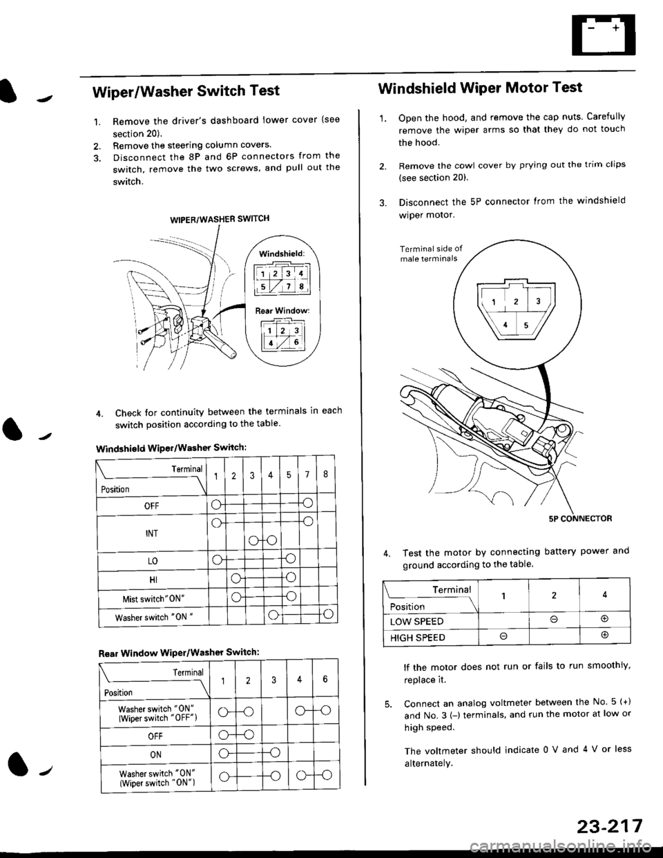
Wiper/Washer Switch Test
Remove the driver's dashboard lower cover {see
section 20).
Remove the steering column covers.
Disconnect the 8P and 6P connectors from the
switch, remove the two screws, and pull out the
switch.
4. Check tor continuity between the terminals in each
switch position according to the table
Windshield Wiper/Washer Switch:
Terminal
Position \
12357I
OFFoo
INTo-o
oo
LOoo
HIoo
l\4ist switch"0N"oo
Washer switch "0N "oo
Rear Window WiPer/Washer Switch:
I Terminal
'i"*
--J2346
Washer switch "0N"
(Wiper switch "OFF"lo--oo--o
OFFo--o
ONo--o
Washer switch "0N"
{Wiper switch "0N")o--oo--o
1.
WIPER/WASHER SWITCH
Windshield:
l1 2 314 |
li.l7a,lil
Rear Window:
11 z 3l
lT-,rtl
Windshield Wiper Motor Test
1.Open the hood, and remove the cap nuts. Carefully
remove the wiper arms so that they do not touch
the hood.
Remove the cowl cover by prying out the trim clips
(see section 20).
Disconnect the 5P connector lrom the windshield
wiper motor.
Test the motor by connecting battery power
ground according to the table.
lf the motor does not run or fails to run smoothiy,
replace it.
5. Connect an analog voltmeter between the No. 5 {+)
and No.3 {-) terminals. and run the motor at low or
high speed.
The voltmeter should indicate 0 V and 4 V or less
alternately.
Terminal
i**l*-
-_\14
LOW SPEEDo@
HIGH SPEEDo@
23-217