Page 1802 of 2189
Troubleshooting
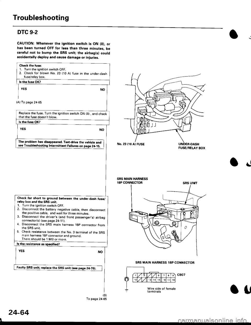
DTC 9-2
CAUTION: Whenever the ignition switch is ON 0l), ofhas been turned OFF lor lass than three minutes, becareful not to bump the SRS unit; the airbag(s) couldaccidentally deploy lnd caqse damage or iniuries.
Check the tu.c:1. Turn the ignition switch OFF.2. Check for blown No. 23 (10 A) fuse in the under,dashfuse/relay box.
Replace the tuse. Turn the ignition switch ON lll) , and checkthat the fuse doesn't blow.
Th6 problem hs3 disappe.rod, TGt-dJiv€ the vehiclo and3ee Troublerhooting Intermiftcnt Failuro3 on paqo 2l-15.
Check tol short to ground betwe.n tho unde.-da3h fus./r.ley box and the SRS unit.1. Turn the ignition switch OFF.2. Disconnect the baftery negative cable, then disconnectthe positive cable, and waittorthree minutes.3. Disconnect the driver's (and front passenger,s) airbagconnector(s) (see page 24-11).4. Disconnect the SRS main harness 1gp connector fromthe sRs unit.5. Check resistance between the No. 3 terminal of the SRSmarn harness 18P connector and ground,There should be 1 MO or more.
Feufty SRS unh; rcphce the SRS unit lsee pag.2+761.
(A)To page 24-65
To page 24-65
No. 23 lr0 Al FUSEFUSE/RELAY BOX
!
SRS MAIN HARNESS18P CONNECTORSRS UN'T
24-64
I
SRS MAIN HARNESS 18P CONNECTOR
Otf
Page 1803 of 2189
)
FUSE/BELAY BOX
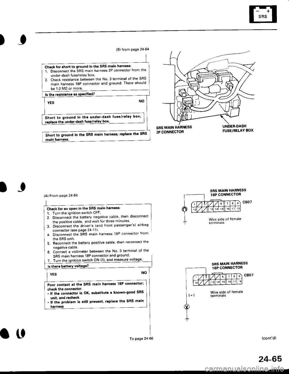
Chcck for an op€n in th6 SRS main harness:
1. Turn the ignition switch OFF.
2. Disconne;t the battery negative cable, then disconnect
the positive cable, and wait for three minutes'
3. Disconnect tho driver's (and front passenger's) airbag
connector (see Page 24'11).
4. Disconnect the SRS main harness 18P connector from
the SRS unit
5. Reconnect the battery positive cable, then reconnect the
neoative cable.
6. Co-nnect a voltmeter betlveen the No 3 terminal ol the
SFS main harness 18P connector and ground'
7. Turn theswitch ON (ll), and m€asure
(cont'd)
(B) from page 24-64
Check tor ahort to ground in the SRS main harn$s:
1. Disconnect the SRS main harness 2P connector from the
under-dash fuse/relaY box.
2. Check resistance between the No. 3 terminal of the SRS
main harness 18P connector and ground There should
be 1.0 M0 or more.
ls the re3istance a3 specified? -
NOYES
Short to giound in tho undot-drlh lut'/rol'y box;
replace the undel-da3h fusgtgEl!9l--------.-
Short to ground in tho SRS m.in harn$s; ropleco the SRS
main harness.
(AlFrom page 24'64
Poor contact at the SRS main harnoss 18P connoctor;
check lho connoctor.. ll the connector k OK, sub3titute r known'good SRS
unh. and recheck. lf the problom is slill present, lepl.ce the SRS main
To page 24-66
SRS MAIN HARNESS18P CONNECTOR
o0
24-65
Page 1804 of 2189
Troubleshooting
DTC 9-2 (cont'dl
2- Disconnect the SRS rnain harness 2p connector lrom theunder-dash fuse/relay box.3- Check resistance between the No. 2 terminal of the SRSmain harness 2P connecior and No. 3 terminal of theSFS main harness 18P connector_
Poor contact at the SRS main ha.ness 2p connector;check the connecto... lf the connector is Ol(, sub3titute a known-good under-dash tuse/r€lay box, and recheck.'lt tho problem is still present, replece the SRS main
Open in the SBS main harness; replace the SRS main har_ness,
SRS MAIN HARNESS2P CONNECTOR
24-66
I
\
From page 24-65
Chock tor an open in th€ SRS main hern€ss:1. Turn the ignition switch OFF.
There should be 0 0.5 0
SRS MAIN
SRS MAIN HARNESS18P CONNECTOR
o!
Page 1815 of 2189
6. Install the new SRS unit.
NOTE: Do not reuse a torx bolt that has red
threads. Replace the bolt with a new one.
)
7.
TORX BOLTS9.8 N.m l'1.0 kg{.m, 7.2 lbf.ft}Use a Torx T30 bit.
Connect the SRS main harness l8P connector to the
SRS uniu push it into posjtion until it clicks.
Install the SRS unit covers (ri9ht and left). Make
sure the covers snap together in the middle.
8.
TORX BOLTS9.8 N.m 11.0 kgf.m, 7.2 lbf.ft)U3e . Torx T30 bit.
SRS MAIN HARNESS
)(l
9.
10.
't2.
Reconnect the driver's aibag 2P connector to the
cable reel 2P connector, then reinstall the access
panel on the steering wheel.
Reconnect the tront passenger's airbag connector
to the SRS main harness.
Reconnect the battery positive cable, then the nega
tive cable.
After installing the SRS unit, confirm proper system
operation: Turn the ignition switch ON (ll); the SRS
indicator light should come on for about six seconds
and then go oif.
11.
24-77
.-
Page 1831 of 2189
How To Use This Manual
Troubleshooting Tests
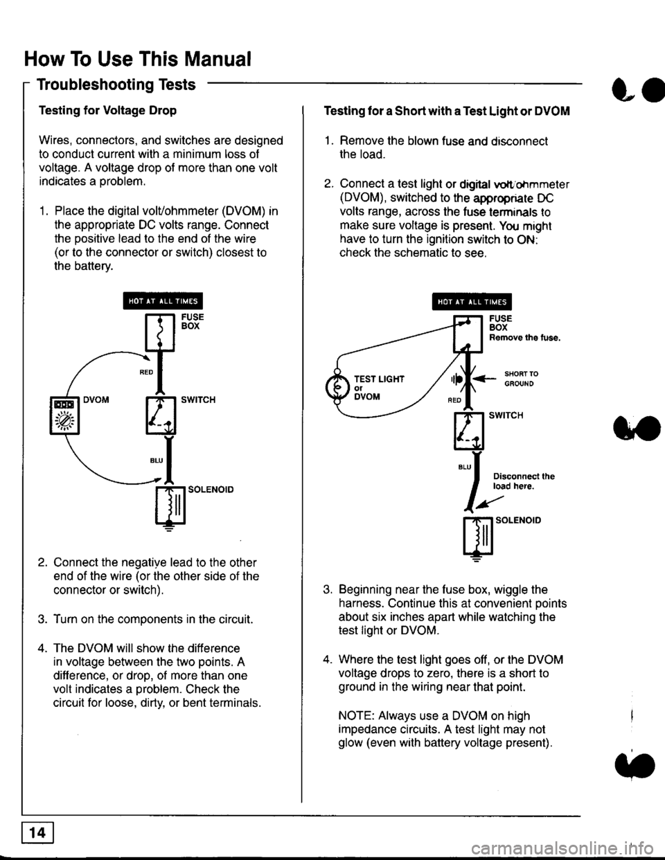
Testing for Voltage Drop
Wires, connectors, and switches are designed
to conduct current wilh a minimum loss of
voltage. A voltage drop of more than one volt
indicates a Droblem.
'1. Place the digital volVohmmeter (DVOM) in
the appropriate DC volts range. Connect
the positive lead to the end of the wire
(or to the connector or switch) closest to
the bafterv.
Connect the negative lead to the other
end of the wire (or the other side of the
connector or switch).
Turn on the components in the circuit.
The DVOM will show the difference
in voltage between the two points. A
difference, or drop, of more than one
volt indicates a oroblem. Check the
circuit for loose, dirty, or bent terminals.
co
Testing lor a Short with a Test Light or DVOM
1. Remove the blown fuse and disconnect
the load.
2. Connect a test light or digital
oltr'ohmmeter
(DVOM), switched to the appropnare DC
volts range, across the tuse lerminals to
make sure voltage is present. You might
have to turn the ignition switch to ON:
check the schematic to see.
<-s80RT TOGFOUNO
Disconnecl lheload here.
Beginning near the luse box, wiggle the
harness. Continue this at convenient ooints
about six inches apart while watching the
test light or DVOM.
Where the test light goes off, or the DVOM
voltage drops to zero, there is a short to
ground in the wiring near that point.
NOTE: Always use a DVOM on high
impedance circuits. A test light may not
glow (even with battery voltage present).
3'�'
ffito.'"o'o
.t.
TEST LIGHTolDVOM
Page 1834 of 2189
![HONDA CIVIC 1996 6.G Workshop Manual Fuse/Relay Information
- Under-dash Fuse/Relay Box
Front View
c712(To moonroof wire harness)
. : Canadai : Not UsedO : C926 loprion (+B)l
@ : C927 loption (dash lights)]
O : C928 [Option (ACC]I
@ : C9 HONDA CIVIC 1996 6.G Workshop Manual Fuse/Relay Information
- Under-dash Fuse/Relay Box
Front View
c712(To moonroof wire harness)
. : Canadai : Not UsedO : C926 loprion (+B)l
@ : C927 loption (dash lights)]
O : C928 [Option (ACC]I
@ : C9](/manual-img/13/6068/w960_6068-1833.png)
Fuse/Relay Information
- Under-dash Fuse/Relay Box
Front View
c712(To moonroof wire harness)
. : Canadai : Not UsedO : C926 loprion (+B)l
@ : C927 loption (dash lights)]
O : C928 [Option (ACC]I
@ : C929 loption (lc2)l
Rear View
css2
c421(To main wire harness)
c801CI-o SRS main harness)
c501(To dashboard wire harness)
^ : Not used ('96-'97 models)
c913(To ignition switch)
INTEGRATEDCONTROL UNITCONNECTOR A
c419Oo main wire harness)
REAR WINDOWDEFOGGER RELAY
TURN SIGNAUHAZARD RELAY
c423(To main wire harness)
co
c422(To main wire harness)
POWERwtNDowRELAY
c551flo lloor wire harness)c439 f96.'97 MODELSand ALL GX MOOELS)(To main wire harness)
T1 T-t T"l T"t r-r r-'l T1 F n r-l r-l r'123 24 25 26 27 28 29 30 31 32 33I-J I.J I.J IJ IJ IJ LJ IJ IJ I.J I.J I-I
r"1 r-t r-t T-l r"l r-r Fl r:1 n rJ n -12 13 14 t5 16 17 t8 19 2A 2t 22LI I.J L! LI tJ LJ (J LI IJ IJ T-I I.J
n r:l rj.l |-l T"l Tl r:t n r-l |;.l r-r r-l1 2 3 4 5 6 7 I 9 10 11LI LI IJ LJ LJ I,J T-I I.J TJ IJ I.-I tJ
c420(To main wire harness)
6
(To floor wire harness)
Page 2030 of 2189
Power Door Locks (cont'd)
Keyless Entry Does Not Work In Any
Mode
NOTE: Before beginning, verify that all the
transmitters are programmed to the vehicle.
1 . Does the radio work properly?
Yes - Go to step 9.
No - Go to the neld step.
NOTE: For steos 2 - 8. refer to the schematic dia-
gram for the Stereo Sound System on page 150.
2. Are fuses 28 (in the under-dash fuse box) and
fuse 47 (in the under-hood fuse box) OK?
Yes - Go to step 4.
No - Replace the blown fuse, then go to the
nen steo.
3. Does the fuse blow again?
Yes - Locate and repair the short.
No- Retest the system.
4. ls the vehicle equipped with the optional security
system?
Yes - Go to the next steP.
No - Go to steD 6.
5. Does the keyless entry work correctly when the
security control unit connector is disconnected?
Yes - Faulty security system, go to security
system for f urther troubleshooting.
No - Go to the next step.
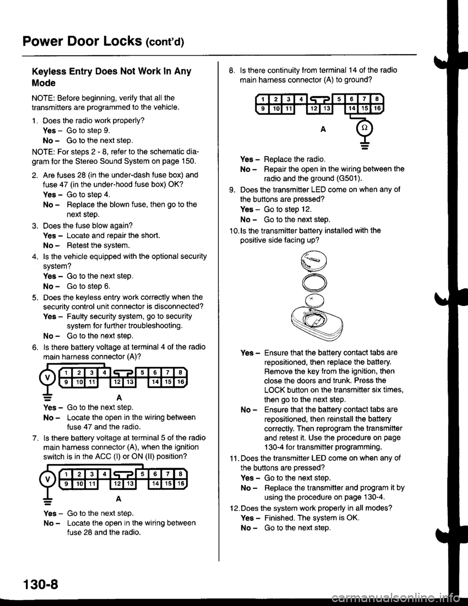
6. ls there battery voltage at terminal 4 of the radio
main harness connector (A)?
7.
=A
Yes - Go to the nen step.
No - Locate the open in the wiring between
tuse 47 and the radio.
ls there battery voltage at terminal 5 of the radio
main harness connector (A), when the ignition
switch is in the ACC (l) or ON (ll) position?
Yes - Go to the next step.
No - Locate the open in the wiring between
fuse 28 and the radio.
130-8
8. ls there continuity from terminal 14 of the radio
main harness connector (A) to ground?
Yes - Replace the radio.
No - Repair the open in the wiring between the
radio and the ground (G501).
9. Does the transmitter LED come on when any ot
the buttons are oressed?
Yes - Go to steo 12.
No - Go to the next steo.'10.ls the transmitter battery installed with the
positive side facing up?
Yes - Ensure that the battery contact tabs are
repositioned, then replace the battery.
Remove the key from the ignition, then
close the doors and trunk. Press the
LOCK button on the transmitter six times,
then go to the next step.
No - Ensure that the baftery contact tabs are
repositioned, then reinstall the batlery
correctly. Then reprogram the transmitter
and retest it. Use the procedure on page
1 30-4 f or transmitter programming.
11 . Does the transmitter LED come on when any of
the buttons are oressed?
Yes - Go to the next step.
No - Replace the transmitter and program it by
using the procedure on page 130-4.
12.Does the system work properly in all modes?
Yes - Finished. The system is OK.
No - Go to the next steD.
Page 2032 of 2189
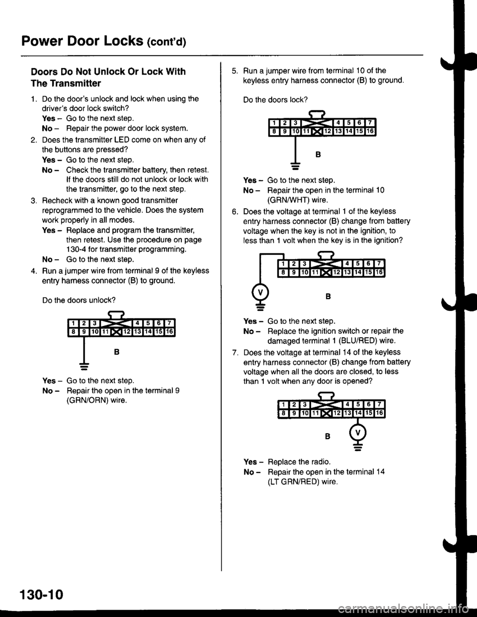
Power Door Locks (contd)
Doors Do Not Unlock Or Lock With
The Transmitter
1. Do the door's unlock and lock when usinq the
driver's door lock switch?
Yes - Go to the next step.
No - Repair the power door lock system.
2. Does the transmitter LED come on when anv of
the buttons are oressed?
Yes - Go to the next steo.
No - Check the transmitter battery, then retest.
It lhe doors still do not unlock or lock with
the transmitte( go to the next step.
Recheck with a known good transmitter
reprogrammed to the vehicle. Does the system
work properly in all modes.
Yes - Replace and program the transmitter,
then retest. Use the procedure on page
1 30-4 f or transmitter programming.
No- Gotothe next step.
Run a jumper wire from terminal I of the keyless
entry harness connector (B) to ground.
Do the doors unlock?
Yes - Go to the next steD.
No - Repair the open in the terminal 9
(GRN/ORN) wire.
130-10
5. Run a jumper wire from terminal 10 ol the
keyless entry harness connector (B) to ground.
Do the doors lock?
ves - Go to ttie next steo.
No - Repair the open in the terminal 10
(GRN/vVHT) wire.
Does the voltage at terminal 1 of the keyless
entry harness connector (B) change from battery
voltage when the key is not in the ignition, to
less than 1 volt when the key is in the ignition?
7.
Yes - Go to the next step.
No - Replace the ignition switch or repair the
damaged terminal 1 (BLU/RED) wire.
Does the voltage at terminal 14 of the keyless
entry harness connector (B) change from battery
voltage when all the doors are closed, to less
than 1 volt when any door is opened?
Yes - Replace the radio.
No - Repair the open in the terminal 14
(LT GRN/RED) wire.