Page 1936 of 2189
?uTi'i'------lUNDER.OASHFUSE/RELAYBOX
UNDER-HOODFUSE/RELAYBOXfI,€! PtfiP
f#rntt)See PowerDistribution,
iT;;*-l
rr:_i
y;lftr,.:{'
page 10-2.tJ---------J" Y 3,,t"?:"""""T
[']':.
i-?;;ffi;
i_f___
PGM-FIMAINRELAY
;;II
;;;I
c't0'l
vtEw 28
TI
":{
c130Oerminals l4-17)
vlEw 52
I . (rGP1) i 1rGP2) - I
Power input
..���������������
SeePGM,FI
POWER.TRAINCONTROLMODULE(PcM)PHO|O 86
(cont'd)
\!
CW hansm|ssion_ control solonoids Ground I
t (HLC LS-) THLCLS+) (SCLS-) (SCLS'I iSH LS I rSHLS+j ISOLINHI lPGr) (PO2) (LG1) rLG2r IL-------i:---- ---------J
-T1
Tj
:1 ;
lruffil
GRNBLII
cl16(Terminals8-14)
vlEW 39BLK
CVTTRANS.MISSIONSOLENOID
See GroundDistribution,page 14-2.
BRN/BLK
PH.PL START SHtF'CONTROL CLUTCH CONTNOLUN€AR CONTNOL LINEARSOLENOID UI{EAR SOLENOIDsoLEltotD
:_-:_-___1
-t
1-! |
Ti11:a__J
BRN/BLK
39-13
Page 1946 of 2189
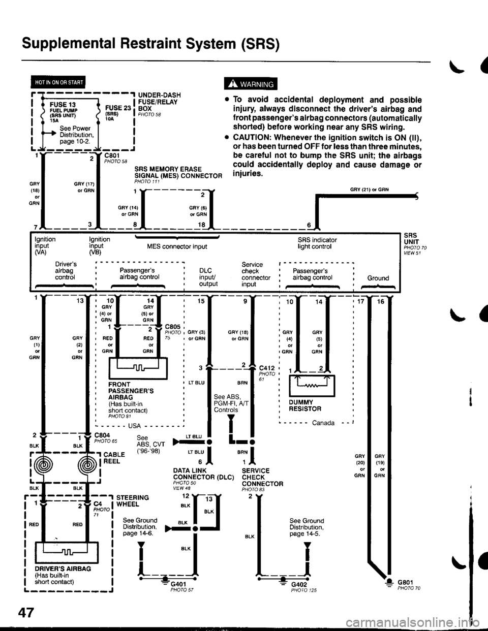
Supplemental Restraint System (SRS)
(
FUSE 13FUELPUUPFBA UMT)15A
See PowerDistibution,page 10-2.
FUSE 23(sRs)
c801PHOTO 58
SRS MEMORY ERASESTGNAL (MES) CONNECTORPHO|O 111
. To avoid accidental deployment and possible
iniury always disconnect the driver's airbag and
f ront passenger's airbag connectors (automatically
shorted) before working near any SRS wiring.
. CAUTION: Whenever the ignition switch is ON (tt),
or has been turned OFF for less than three minutes,
be caretul not to bump the SRS unit; the airbags
could accidentally deploy and cause damage or
iniuries.
UNDER-DASHFUSE/RELAYBOX
GFY 07)or GFN{18)
GFN
GFYt2l
GFN
GRY0)
GFN
2
ALK
J (ii
t\
GFY O4)or GRN
SRSUNIT
a
-ffiffi,*l-{
H!=";=_J
iffii'r:fi:*" i tH-
PHOIO 125short contact) | - FCqOtL_________J PHO|A 57
47
GAY (21) or GRN
lgnitionInput(VA)
Driver's
cont.ol
lgnitioninput(VB)MES connector inputSRS indicatorlighl control
Service t------check : Passengefs ;connector ; airbag control , GroundInpu , /+rr I pir-r
Passenger'sai|bag conlrol; prc..t rnpuv, Ourpul
14GRY(5) orGFN
rffi{{_ilil
i ffi i""'"1*"o,"'.1'' i lffil
ffirtu!-T:l
ir:r*::"."
ilstEl'{s6.e8'�
'"'Jl "Tl
, I oATA L|NK SERVTCE: CoNNECTOR (DLC) CHECK,J piarasa CONNECTORvtEw48
Page 1957 of 2189
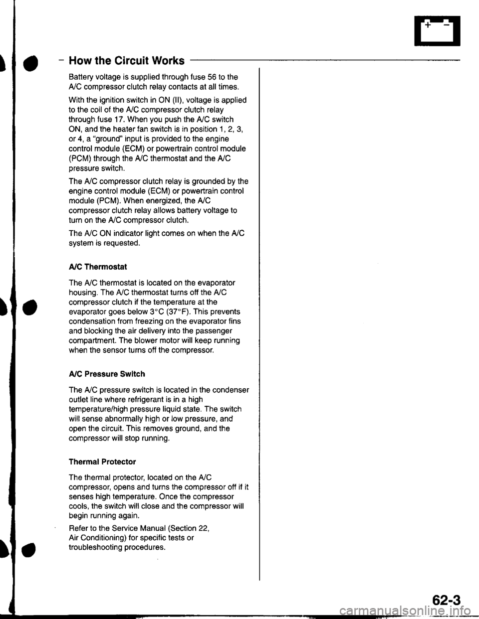
- How the Circuit Works
Battery voltage is supplied through tuse 56 to the
A,/C compressor clutch r€lay contacts at all times.
With the ignition switch in ON (ll), vollage is applied
to the coil of the A,/C compressor clutch relay
through fuse 17. When you push the A,/C switch
ON, and the heater fan switch is in position | , 2, 3,
or 4, a "ground" input is provided to the engine
control module (ECM) or powertrain control module
(PCM) through the l'lC thermostat and the l'lC
pressure switch.
The A,/C compressor clutch relay is grounded by the
engine control module (ECM) or powertrain control
module (PCM). When energized, the A'lC
compressor clutch relay allows battery voltage to
turn on the A,/C comDressor clutch.
The A,/C ON indicator light comes on when the A,/C
system is requested.
A,/C Thermostat
The A'lC thermostat is located on the evaoorator
housing. The A,/C thermostat turns off the A,/C
compressor clutch if the temperature at the
evaporator goes below 3'C (37'F). This prevents
condensation from freezing on the evaporator fins
and blocking the air delivery into the passenger
compartment. The blower motor will keep running
when the sensor turns off the comDressor.
A,/C Pressure Switch
The fuC oressure switch is located in the condenser
outlet line where refrigerant is in a high
temperature/high pressure liquid state. The switch
will sense abnormally high or low pressure, and
open the circuit. This removes ground, and the
compressor will stop running.
Thermal Protectot
The thermal protector, located on the A,/C
compressor, opens and turns the compressor off if it
senses high temperature. Once the compressor
cools, the switch will close and the compressor will
begin running again.
Refer to the Service Manual (Section 22,
Air Conditioning) for specific tests or
troubleshooting procedures.
62-3
Page 1958 of 2189
Fans
- AllModels\,1 |
splicedtogetherinstead of inthe junctionconnector onDl6Y5 models
c211PHOTO 11
FANRELAYPrtofo 10
Se€ I'i CCompre€sorCont ols
1
ALKAED
a
c352
f BLKaEou Y 9,;%,.cFN I vIEw 5e
;
"'
T
";::-:.."-!
Y:. ---::Y h!ii'in"," :
I : ""'I 'is.2o) :
I i,o''ur,ff;, l;l:'l?'* i
I r- - -, |JBEI :
I ; I control | ;
I :L--J :I ' PoWERTRAIN ordu. ' ENGINE CONTROL '' MODULE
: (PCMoTECM) :I PHAfO 86I wEw 7allqA ----.ENGINECOOLANTTEMPERATUREswtrcH BLLPHO|O 33 ?
Ses GrolndDiskibution,oaqe 14.
,I
H
:I
i:
"'*
1_l
c7531
BLU/BLK
ALK2
BLK
RADIATORFANMOTORI
BLK
BLK1
ELK
c753
CONDENSERFANMOTOR
a
* czsr
page 14.
II
FJ'Glot
c211
Gro!nd
T
Se€ GroundOstribution,Pago 14.4"t1 - '96.f98: All models'99-'00: 016Y5 with M/I 01685"2 = '99-'00: Allmodels exceptD16Y5 with M/T and 01685
cof{oENs€R
* czor33123lCVIl
63
Page 1961 of 2189
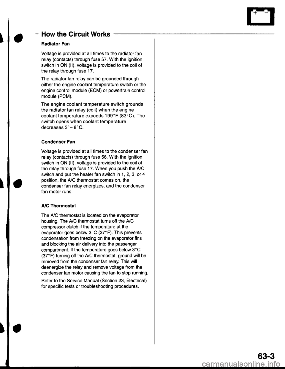
- How the Circuit Works
Radiator Fan
Voltage is provided at all times to the radiator fan
relay (contacts) through fuse 57. With the ignition
swilch in ON (ll), voltage is provided to the coil of
the relay through luse 17.
The radiator tan relay can be grounded through
either the engine coolant temperature switch or the
engine control module (ECM) or powertrain control
module (PCM).
The engine coolant temperature switch grounds
the radiator fan relay (coil) when the engine
coolant temperature exceeds 199'F (83'C). The
switch opens when coolanl temperature
decreases 3'- 8'C.
Condenser Fan
Voltage is provided at all times to the condenser fan
relay (contacts) through fuse 56. With the ignition
switch in ON (ll), voltage is provided to the coil of
the relay through fuse 17. When you push the A'lC
switch and put the heater fan switch in 1, 2,3, o( 4
position, the ly'C thermostat comes on, the
condenser fan relay energizes, and the condenser
fan motor runs.
A,/C Thermostat
The A,/C thermostat is located on the evaporator
housing. The A,/C thermostat tums off the A/C
compressor clutch if the temperature at the
evaporator goes below 3'C (37'F). This prevents
condensation from freezing on the evaporator fins
and blocking the air delivery into the passenger
compartment. lf the temperature goes below 3'C
(37"F) tuming off the Ay'C thermostat, ground will be
removed from the condenser fan relay. This will
deenergize the relay and remove voltage from the
condenser fan motor causing the fan to stop running.
Reter to the Service Manual (Section 23, Eleckical)
for specific tests or troubleshooting procedures.
63-3
Page 1979 of 2189
GAUGEASSEMBLYf
l-*
,'
I
t
\
\
I
I
,
,:
ENGlrlECOOLANTTEiTPERATNEGAI'GE
FUELGAUGE
--------J
GX modelBl2
tr' Alt€xcsp't Gx mod€t B1o
IYEUGFN I
,r, A "oll "., ","11"
fi;rt"r4." ,1,"g[ s;g,,YEUGFN I 2lvtuea
r-----.|FUEL
- A ^.^. I |fl Fuer lll,l5
-*"L[
F*H4''
L
t#4iorn-i'**
-
t '-;5-
OFN/BLU
OFN/BLU
OFN
A4
c410
vlEw 35
c131
vtEw 59
r --= .I POWERTRAIN
!r+i-'' !fi8tsllP.
331ffi !i;E-i/'i
#."o,". t f
14
ii11"t:'f""'
*!--*
il?:+:ifll--JvtEwzo
81-1
Page 1983 of 2189
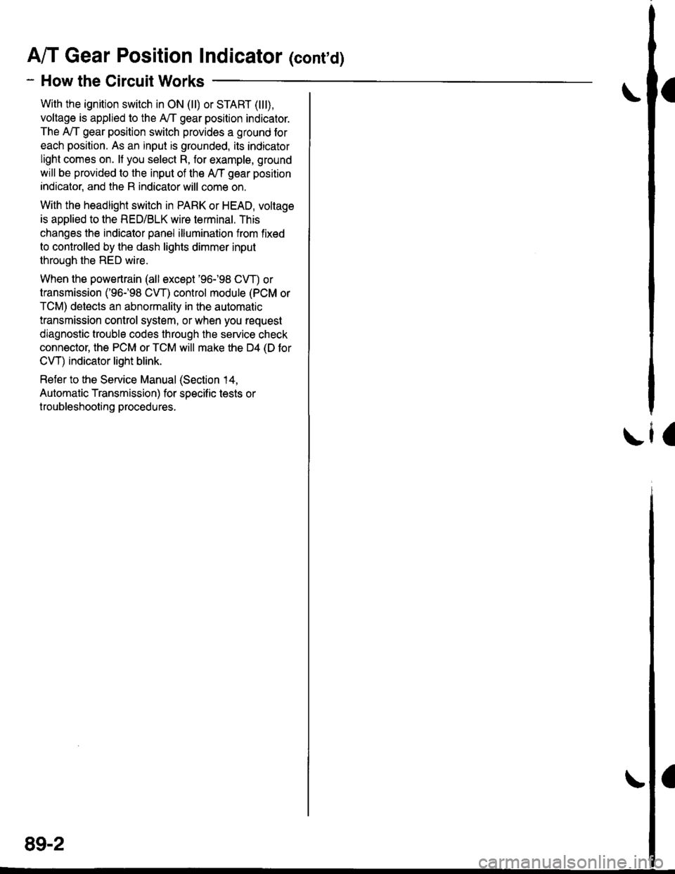
A/T Gear Position Indicator (conrd)
- How the Circuit Works
With the ignition switch in ON (ll) or START (lll),
voltage is applied to the A,/T gear position indicator.
The A,/T gear position switch provides a ground for
each position. As an input is grounded, its indicator
light comes on. lf you select R, for example, ground
will be provided to the input of the A,/T gear position
indicato( and the R indicator will come on.
With the headlight switch in PARK or HEAD, voltage
is applied to the RED/BLK wire terminal. This
changes the indicator panel illumination from fixed
to controlled by the dash lights dimmer input
through the RED wire.
When the powertrain (all except '96-'98 CVT) or
transmission ('96198 CVT) control module (PCM or
TCM) detects an abnormality in the automatic
transmission control system, or when you request
diagnostic trouble codes through the service check
connector, the PCM or TCM will make the D4 (D for
CVT) indicator light blink.
Refer to the Service Manual (Section 14,
Automatic Transmission) for specific tests or
troubleshooting procedures.
\ia
89-2
Page 2108 of 2189
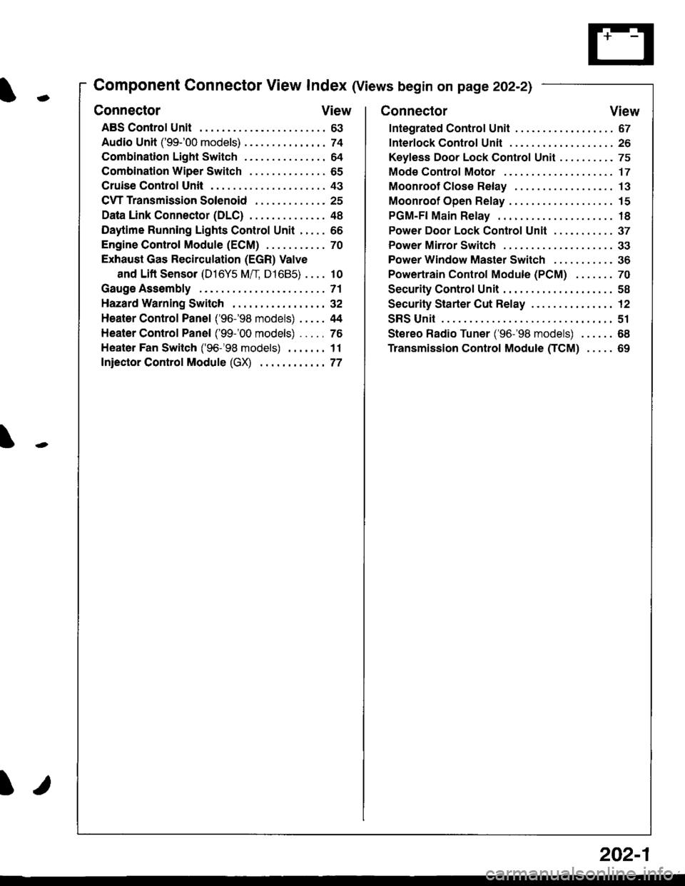
-
Component Connector View Index (Views begin on page 202-21
Connector View
ABS Control Unit........ ......63
Audio Unit ('99-'00 models) ......74
Combination Light Switch . . . . . . . . . . . . . . . 64
Combination Wiper Switch . . . . . . . . . . . . . . 65
Cruise Control Unit.... .....43
C\TTTransmission Solenoid ............. 25
Data Link Connector (DLC) ..... 48
Daytime Runnlng Lights Control Unit ..... 66
Engine control Module (ECM) ...........70
Exhaust Gas Recirculation (EGR) Valve
and Lift Sensor (D16Y5 Mfl, D1685) . . . . 10
Gauge Assembly .............71
HazardWarnlngSwitch,,. .,,,...,,,,... 32
Heater Control Panel ('96-'98 models) .....44
Heater Control Panel ('99-'00 models) ...., 76
Heater Fan Switch ('96-'98 models) ,,,.... 11
fniector Control Module (GX) ............77
I/
202-1
Connector View
Integrated Control Unit .......,. 67
f nterfock Control Unit .... ...... 26
Keyfess Door Lock Control Unit . . . . , . . . . . 75
Mode Control Motor ... ........'17
Moonroof Close Relay .. .......13
Moonroof Open Relay ... .......15
PGM-FI Main Relay .. .......... 18
Power Door Lock Conlrol Unil ..... ...... 37
Power Mirror Switch .,... ...... 33
Power Window Master Switch .,.........36
Powertrain Control Module (PCM) .......70
Security Control Unit ..., ..,,... 58
Security Starter Cut Belay ... ...,,,....,, 12
SRS Unit ............. 51
Stereo Radio Tuner ('96-'98 models) ...... 68
Transmission Control Module CICM) .....69