Page 1272 of 2189
Quarter Glass
Installation (cont'd)
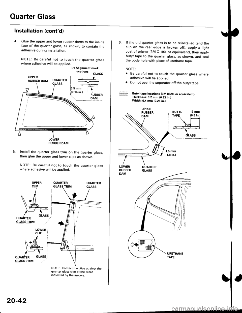
4. Glue the upper and lower rubber dams to the insideIace of the quaner glass, as shown, to contain theadhesive during installation.
NOTE: Be careful not to touch the quarter glasswhere adhesive will be applied.>: Alignment marklocationsGLASSUPPERRUBBER DAM
LOWERRUBEER DAM
Install the quarter glass trim on the quarter glass,then glue the upper and lower clips as shown.
NOTE: Be careful not to touch the quarter glasswhere adhesive will be applied.
OUARTERGLASS TRIMOUARTERGLASS
GLASS TRIM
NOTE: Contact the cljps against thequarter glass trim at the areasIndicated by the arrows.
UPPER
20-42
6. lf the old quarter glass is to be reinstalled (and theclip on the rear edge is broken off), apply a lightcoat of primer (3I/ C-100, or equivalent), then applybutyl tape to the quarter glass, as shown. and sealthe body hole with piece of urethane tape.
NOTE:
. Be careful not to touch the quaner glass whereadhesive will be applied,. Do not peel the separator offthe butyltape.
//////// '. 8�u'Jt tape tocarions t3M 8628, or equivetenrl' Thickness:3.2 mm lo.t3 in.lWidth: 6.4 mm {0.25 in.)
BUTYL 13 mmTAPE (0.5 in.l
\\l
,7r--/r4--;*--T-
.. GLASS
UPPERRUEBERDAM
Page 1274 of 2189
Ouarter Glass
Installation (cont'd)
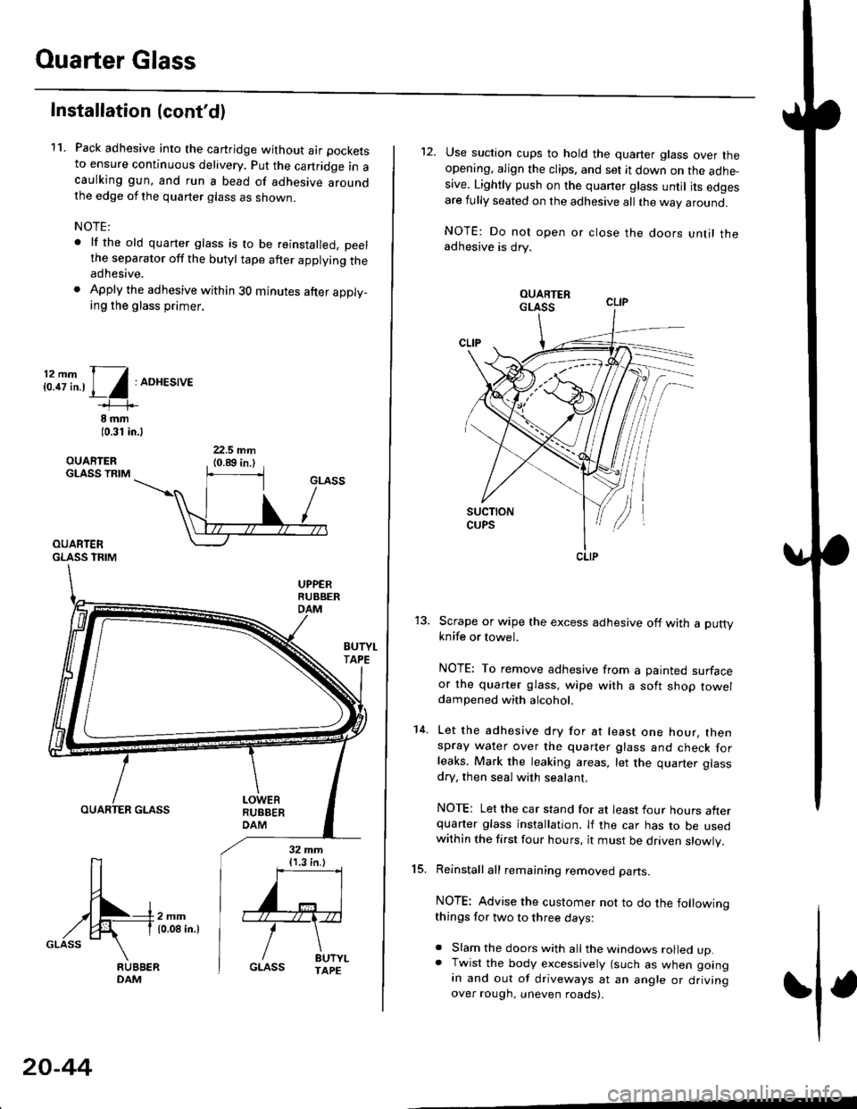
11. Pack adhesive into the cartridge without air pockets
to ensure continuous delivery. put the canridge in acaulking gun, and run a bead of adhesive aroundthe edge of the quarter glass as shown.
NOTE:
. lf the old quarter glass is to be reinstalled, peelthe separator off the butyl tape after applying theadhesive.
. Apply the adhesive within 30 minutes after apply_ing the glass primer.
i:.8i".,1/:ADHES,'E
8 rnm(0.31 in.l
OUARIERGLASS TRIM
OUARTERGLASS TFIM
BUTYI.TAPE
OUARTER GLASS
[-4m,^,GLASS \
32 mm{1.3 in.)
''='I
'"r"\
/ drt".GLASS TAPE
20-44
12. Use suction cups to hold the quarter glass over theopening, align the clips, and set it down on the adhe-sive. Lightly push on the quaner glass until its edgesare fully seated on the adhesive all the way around.
NOTE: Do not open or close the doors until theadhesive is drv.
Scrape or wipe the excess adhesive off with a puttyknife or towel.
NOTE: To remove adhesive from a painted surfaceor the quarter glass, wipe with a soft shop toweldampened with alcohol.
Let the adhesive dry for at least one hour, thenspray water over the quarter glass and check forleaks. Mark the leaking areas, let the quarter glass
dry, then seal with sealant.
NOTE: Let the car stand for at least four hours afterquarter glass installation. lf the car has to be usedwithin the first four hours, it must be driven slowly.
Reinstall all remaining removed parts.
NOTE: Advise the customer not to do the followingthings for two to three days:
. Slam the doors with all the windows rolled up.. Twist the body excessively (such as when goingan and out of driveways at an angle or drivingover rough, uneven roads).
15.
14.
CLIP
Page 1278 of 2189
Ouarter Glass
Installation (cont'dl
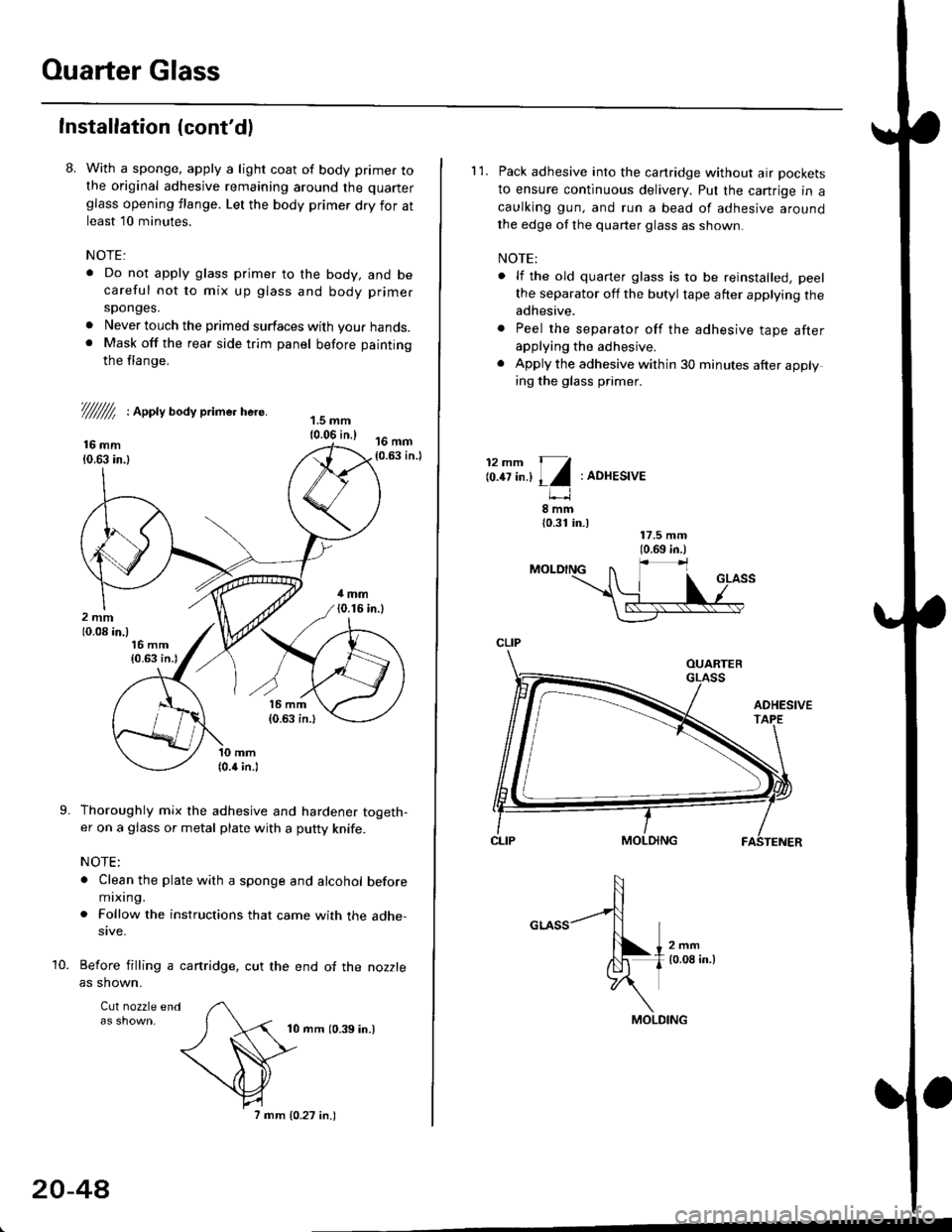
8. With a sponge, apply a light coat of body primer tothe original adhesive remaining around the quarter
glass opening flange. Let the body primer dry for atleast l0 minutes.
NOTE:
. Do not apply glass primer to the body, and becareful not to mix up glass and body primer
sponges.
. Never louch the primed surfaces with your hands.. Mask off the rear side trim panel before painting
the flange.
///ffi : Appty aoay primer here.
16 mm10.63 in.l
Thoroughly mix the adhesive and hardener togeth-er on a glass or metal plate with a putty knife.
NOTE:
. Clean the plate with a sponge and alcohol beforemixing.
. Follow the instructions that came with the adhe-sive.
Before filling a cartridge, cut the end of the nozzle
as shown.
Cul nozzle end
10 mrn (0.39 in.)
9.
10.
20-4A
7 mm 10.27 in.)
l'1. Pack adhesive into the canridge without air pockets
to ensure continuous delivery. Put the cartrige in a
caulking gun, and run a bead of adhesive around
the edge of the quarter glass as shown.
NOTE:
. lf the old quarter glass is to be reinstalled, peel
the separator off the butyl tape after applying theadhesive.
. Peel the separator off the adhesive tape afterapplying the adhesive.
. Apply the adhesive within 30 minutes after applying the glass primer.
12mm 11
lo.tt tn.l I l:ADHESIVE
8mm{0.31 in.)
CLIP
MOLDING
Page 1295 of 2189
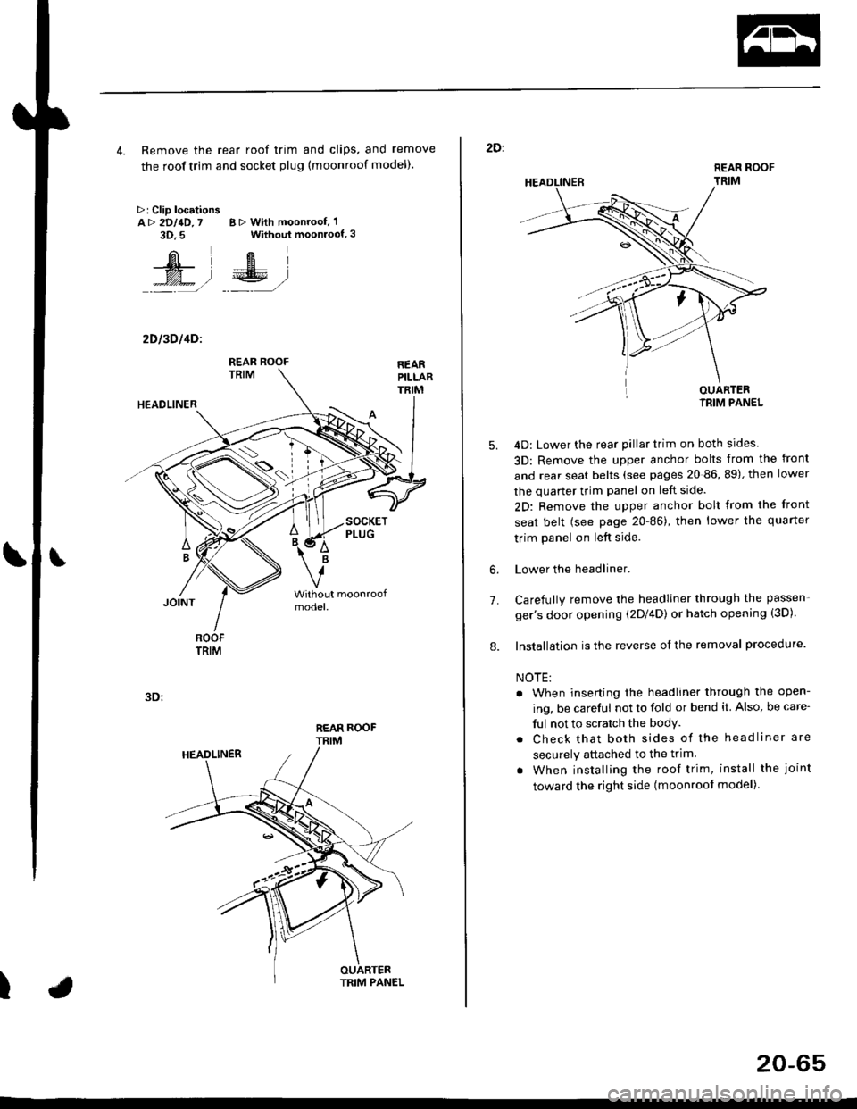
4. Remove the rear roof trim and clips, and remove
the roof trim and socket plug (moonroof model).
>: Clip locationsA> 2DllD,7 B > With moonroof, 'l
3D.5 Without moonroof,3
[il',fEl
t% .l €E .l':: =,/ _._- ,/
2D l3D l4Dl
REAR ROOFTRIM
3D:
t
REAR ROOF
TRIM
2D:
5.
7.
OUARTERIRIM PANEL
4D: Lower the rear pillar trim on both sides
3D: Remove the upper anchor bolts from the front
and rear seat belts (see pages 20-86, 89), then lower
the quarter trim panel on left side.
2D: Remove the upper anchor bolt from the front
seat belt (see page 20-86), then lower the quaner
trim panel on left side.
Lower the headliner.
Carefully remove the headliner through the passen-
ger's door opening (2Dl4D) or hatch opening (3D).
Installation is the reverse of the removal procedure.
NOTE:
. When inserting the headliner through the open-
ing, be careful not to fold or bend it. Also, be care-
ful not to scratch the bodY.
. Check that both sides of the headliner are
securely attached to the trim.
. When installing the roof trim, install the joint
toward the right side (moonroot model)
6.
8.
20-65
Page 1304 of 2189
Front Seat
Removal
CAUTION: When prying with a flat-tip screwdriver, wrapit with protective tape lo prevent damage.
NOTE: Take care not to scratch the seat covers and body.
1. Remove the seat track end cover, then remove thebolts.
SEAT TRACKCOVER
FRONT SEAT
)
SEAT TRACKEND COVER
BOLT8 x'1.25 mft22 N..n 12.2 kgl.m,16 rbf.ft)
8 x 1.25 mm22 N.rn 12,2 kgl.m,16 tbtft)
20-74
2. Lift the driver's front seat, then disconnect the seatbelt switch connector.
SEAT BELTswtTcHCONNECTOR
4.
Remove the headrest.
Carefully remove the front seat through the dooropening.
Installation is the reverse ol the removal procedure.
NOTE: Make sure the connector is connected prop-
erry.
5.
Page 1306 of 2189
Front Seat
Replacement (cont'd)
Passenger's (with reclino cablel:
NOTE; Refer to page 20-77 for the recline cable location.
HEADREST
PIVOTWASHER
LOWERCAP
PIVOT NUT8 x 1.25 mm22 N.m 12,2 kgl.m,tbt.ftt
SEAT CUSHION
CENTER COVER
10 x 1,25 mm47 N.m (4.8 kgf.m,
10 x 1.25 mm47 N.m {4.8 kgf.m,3s tbt.ft)
INNER SEATTRACK
35 tbf.ftl
RECLINE ADJUSTEB
RECLINECOVER
i LowER CAP
bRECLINECABLE
x 1.25 mm47 N'm (4.7 kgf.m,35 tbtftl
SEAT
8 x 1.25 mm20 N.m {2.0 kgf.m,14 rbf.ft)
ruf, To connect, twist 180'.
lnstallation is the reverse of the removal procedure.
NOTE:
. Make sure the bushing and pivot washer are
installed properly.
. To prevent wrinkles when installing the seat-back
cover, make sure the material is stretched evenly
over the pad.
. Adjust the recline cable.
. G.ease the sliding ponion.
SEAT-BACK
20-76
Page 1307 of 2189
Harness Wiring and Recline
Cable Locations
NOTE: When installing the seat cushion, make sure the
seat belt switch harness, connector and recline cable are
fastened correctly on the seat cushion frame'
Driver's:>: Clip locations
Passenger's (with lecline cablel:
TRACK
Seat Cover RePlacement
CAUTION: Put on gloves to protest yout hands'
NOTE: Take care not to tear the seams or damage the
seat covers.
Seat-back cover removal:
1. Release the hook, and fold back the seat-back cover'
Release all inside springs, then fold back the seat-
back cover.
Remove the headrest.
Remove the headrest guide, then remove the seat-
back cover.
lnst;llation is the reverse of the removal procedure'
NOTE: To prevent wrinkles when installing a seat-
back cover, make sure the material is stretched evenly
over the pad before securing the inside springs and
hook.
3.
(cont'd)
20-77
HEADREST
Page 1560 of 2189
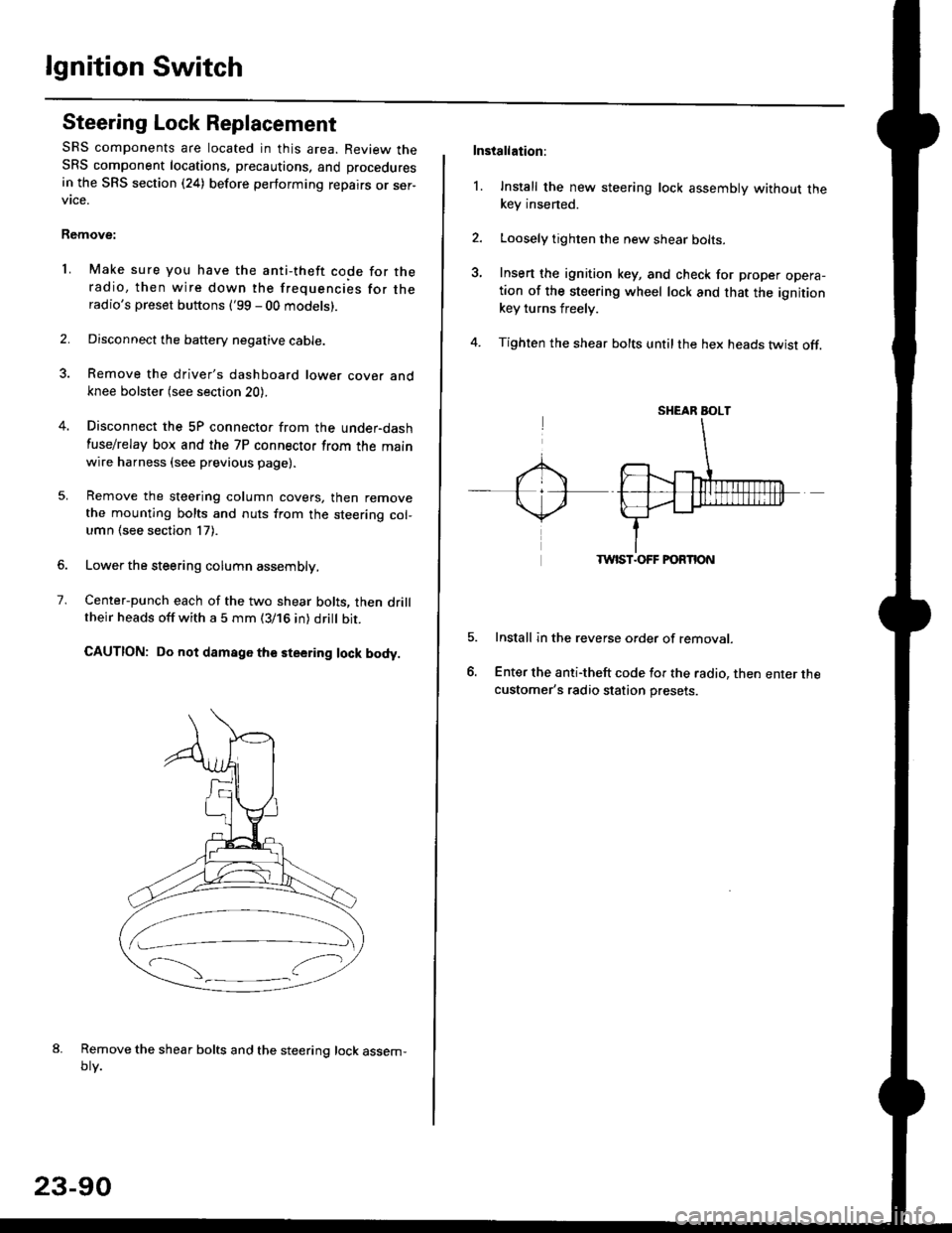
lgnition Switch
Steering Lock Replacement
SRS components are located in this area. Review theSRS component locations. precautions, and procedures
in the SRS section (24) before performing repairs or ser-vtce.
Remove:
LMake sure you have the anti-theft code for theradio, then wire down the frequencies for theradio's preset buttons ('99 - 00 models).
Disconnect the battery negative cable.
Remove the driver's dashboard lower cover andknee bolster (see section 20).
Disconnect the 5P connector from the under-dash
fuse/relay box and the 7P connector from the mainwire harness (see previous page).
Remove the steering column covers, then removethe mounting bolts and nuts from the steering col-umn (see section l7).
Lower the steering column assembly,
Center-punch each of the two shear bolts, then drilltheir heads off with a 5 mm (3/16 in) dritt bit.
CAUTION: Do not damago the steering lock body.
Remove the shear bolts and the steering lock assem,oty.
2.
1.
23-90
Installation:
l. Install the new steering lock assembly without thekey insened.
Loosely tighten the new shear bolts-
Insert the ignition key, and check for proper opera-tion of the steering wheel lock and that the ignitionkey turns freely.
Tighten the shear bolts untilthe hex heads twist off.
TWIST.OFF FORTION
Install in the reverse order of removar.
Enter the anti-theft code for the radio, then enter thecustomer's radio station presets.
sr{€aR SroLT