1996 HONDA CIVIC out
[x] Cancel search: outPage 2025 of 2189
rl
lt,
I vevneo
I veuneo.1I YEUFED
UNDER-HOODFUSE/RELAYBOXi-iffiri
""',;Xftf*',I.'
c557
vtEw 62
c654
FRONT
;l
I
see Power iDistribution. I**t"t:.""."
I
------*-,7
OE
n"r,n"n I
il.",":['
".,"-fifiT""' I
-:iii[::f
PASSENGER'SDOOR LOCKACTUATOR
c554
c557
. VIEW 62
cs56
vtEw61WHT/REO
POWERDOORLOCKCONTROLUNIT
GRN/OBN
tu
GFI{/OBN:
GRN/OFN
ALUAViIT
DOORKEY
4
BLUAVHT
c556PHOfO93vtEw 61
BLU/NED
c634
92YEURED
DRIVER'SDOORLOCKACTUATORDOORLOCKKNOB
DRIVER'SDOOR LOCKswlTcH
WHT/FED
1
I
BLK
22
BLK
I-
c556
vtEw61BLK
YEUFEO=__- , YEUFEO
c5zo : sPHO|O 99 ,VIEW 5 - YEUFEO
C674 ' 1PHO|O95
PHOTO 95 I WHI/REO
C674PHOTO9sI WHT/FEDc570PHOTO ggvtEw 5 . _ryHi/!E9
ACTUATOR .-.:PHO|O 95FED
c664 2PHA|A9S wxf/FED
c571 2
VIEW6 WHT/BEO
Driver'sdoor Batt€ryunlock input input
Unlock Lockanput input
Unlock/loc*ouIpur
Ground
Unlock/lockLock outputinput
[-:I
l_l
t fl!@Klocx
eLxlrat-{ 3'i#i:T:'
!- cssr
Il r
S€s Ground
130-3
Page 2026 of 2189
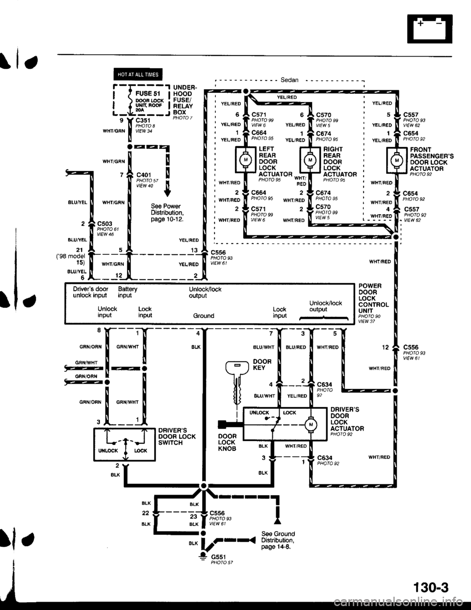
Power Door Locks (cont'd)
- How the Circuit Works
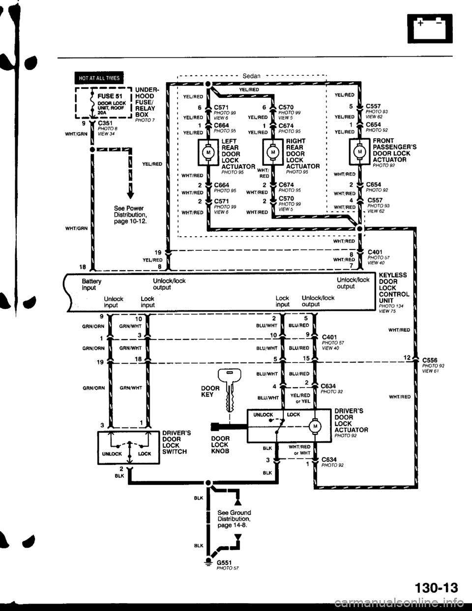
Keyless Entry System
The keyless door locks combine the power door
locks with a remote keyJob transmitter. The keyless
receiver unit is part of the radio. The keyless
receiver unit receives direct inputs f rom the ignition
key switch, the passenger door switches, and an
indirect input trom the driver's door switch through
the integrated control unit.
Power Door Locks (With or Wlthout Keyless)
The power door lock system is made up of the
oower door lock control unit. driver's door lock
switch, and individual door lock actuators. The
power door locks are controlled by the driver's door
lock switch and the driver's door lock actuator
switch.
Transmitter (With Keyless Entry)
The transmitter sends coded radio wave signals to
the keyless receiver unit when one ot its buttons is
pressed. Each transmitter has a unique code that
must be 'laught" to the keyless receiver unit before
it can operate the door locks or any other lunction.
Up to 4 transmitters can be programmed to operate
the keyless door locks.
Door Locking (With or without Keyless Entry)
When you push the driver's door lock switch to the
lock position, ground is applied to the GBN/IVHT
wire to the oower door lock control unit. The control
unit then applies battery voltage to the WHT/RED
wire and ground to the YEURED wire. The
passenger door lock actuators then activate to lock
the corresponding door locks.
When you lock the driver's door with the key or door
lock knob, it is mechanically locked, and the driver's
door lock actuator switch applies ground to the
oower door lock control unit. The control unit then
applies battery voltage to the WHT/RED wire and
ground to the YEURED wire, activating the
passenger door lock actuators which lock the doors.
Dool Locking with Transmitter
When you press the LOCK button on the remote
transmitter, the power door lock control unit applies
battery voltage to the WHT/RED wire and ground to
the YEURED wire. The passenger door lock
actuators then activate and lock the doors. A ground
slgnal is also applied to the BLU/RED wire to lock
the driver's door. lf any door is open, you cannot lock
it using the remote transmitter.
Door Unlocking (With or Without Keyless Entry)
When you push the driver's power door lock switch
to the unlock position, ground is applied to the
GRN/ORN wire to the power door lock control unit.
The control unit then applies battery voltage to the
YEURED and BLU/RED wires and ground to the
WHT/RED wire. The door lock actuators then
activate to unlock the doors.
When you unlock the driver's door with the key or
the door lock knob, it is mechanically unlocked; the
other doors do not unlock.
Door Unlocking (With Transmltter)
When you press the UNLOCK button on lhe remote
transmitter once. the power door lock control unit
applies battery voltage to the WHT/RED wire and
ground to the BLU/RED wire to unlock the driver's
door. When you press the UNLOCK button twice,
the control unit then applies ground to the YEURED
wires to activate the passenger door locks. lf you do
not open a door within 30 seconds after unlocking
the doors with the transmitter, the doors
automatically relock.
Transmltter Programming
1 . Turn the ignition switch ON (ll).
2. Press and hold the Valet-Disarm button on the
radio (between the AM/FM button and the
CD/TAPE button) to enter the programming
mode. (Continue to hold the button during the
procedure, or programming will be cancelled.)
Check that the power door locks cycle to confirm
that you're in the programming mode.
3. Press the "LOCK' or "UNLOCK' button on the
transmitter. Check that the power door locks
cycle to confirm that the code was accepted.
4. Press the "LOCK" or "UNLOCK" button on each
of the remaining transmitters. (You can program
up to four transmitters per vehicle.)
5. After all the transmitters have been
programmed, release lhe Valet-Disarm button to
exit the programming mode.
Beep On/Oft Feature
'I . Press and hold the LOCK and OPTION buttons
on the transmitter.
2. Watch the transmitter's LED:
One flash: Beeo activated.
Two tlashes: Beeo deactivated.
130-4
Page 2035 of 2189
I YEI/BEO
c57o , 5PHOfO 99V\EW 5 ' YEL/BED
c6?4 : 1PHOfAgs , YEUFED
I WHT/FED
c674 i zPHoro 95 i wrvneoc570 , a',;f,tr?"n l-1"1/1.9
I
I
9
WIIT/GRN
f*-.l'il
TryJ
UNDER.HOOOFUSE/RELAYBOX
c557
vlEw 62
c654c351
vlEW 31FRONT
aaa
! ".u".o
!t
+
See PowerDistribution,page 1S12.
PASSENGER'SDOOR LOCKACTUATOR
c654
c557
. vtEw 62
't8
9
GRN/OBN
1
GBN/ONN
19
GRN/OFN
KEYLESSDOORLOCKCONTROLUNIT
WHT/FED
12c556
vlEw 61BLU/BED
;;;oTYEL
BLUAVHT
aLU/'$/HT
4
ALUMHT
(?
***
[J
BLU/FED't5
WHT/REO
c634PHOfa 92
DRIVER'SoooRLOCKACTUATORDRIVER'SDOORLOCKswtTcH
DOORLOCKKNOB
c634PHO|A 92
BLK
BLK"iI-.
l: cssr
Battsrv UnloclvlockingJt ' otttputUnlocKlockoutpul
Look Unlock/lockinput outputUnbck LockInput input
fff
LJ-T->J
wrccr I mc.
\.
130-13
Page 2043 of 2189
';;;1; I r1-- --'I UNDE'------J-i i I 11'.1'.11 lSBi'"Driver .r ' HEADIIOriT '::
door !:t { t-- lPHo'o7unlock Unlock Lock | : L j,- -- -Jinpd input lpr,_j : -9lT1u.r^ -
---- Canada ---'------l
POWER DOOR LOCK ;CONTROL UNIT ,
k;i
L______jg:_l=,_______ juj_.r, _r_f 9_.-u:'F":;!-_ --",*tI
i !**""""I
*",*"[T*Fi
i
.",1
o*u*u'
,* -".11 t-J--'-----'-hff I
"ll-_-_il
|semooeriir f,
't
tr
18 f ia-eii,
L______d"t";tlo"n,o"n| """*",|ft"t'i fsEcuRrwLED,, L--J---------J",0. | | -liffi*
,i,Hfil _[l!,ffisHdsh
i ,of.--s L--d,---t--------cl-+-'dl "."""" !-------t - I, t - Drivgr's door Unlock Lock I Light I U
ii -F-o-:y-"1 - -:i"-1i3y. -TTi- - - - - :"ll'i - - ; 13'*" i q._"u_n'r !--1---- ---'l99,trRoL I
: \varst :l;#"b" I; ; $vitch Securiiv Bus Remote Bus Bus i I vttwte ll C422, f inqrt outDut d€,.az LED control data 0 data l , : I P1oTo 58-a- --' s Y---^a---.;f --.;Y---^;Y---:Y - - - - r ;-.tr'---
. ; UNIT
i *t Drtusr's door untock Lock i ugnt it - uavgrs ooor untocx LocK I Lrgn'
: LED control unloc* outpul outrut outpul ' flash- ': ' iontrot I sEcuRlw
--1-"' ---' I coNrRoL' 'i uNlri vatst, I VarEr tl PHQ|AT3: ; s,vitch Securiiy Bus Remote Bus Bus t)vtEwte, f inarr ornout d'de2 LED control data 0 data l� :
7-1 e4re4lon
lfil Iffi;*l
[I$'':r*il
: 84 |, 85A 87A 811 |' Bt2 |' 813 |' vtEw68 | ! sae r.teadli
i i'=::t:::ti------r------s------r, -"** i : ! 8yJfu;; I I Vabt S€curity 8us Remot€ Bus Bus I Reieiver ! ; --_ _.._ ll
:i iffi$ input data2 ffiDul
datao datal iunrr !:""'"^l
(cont'd)
133-1
Page 2055 of 2189
How the Circuit Works
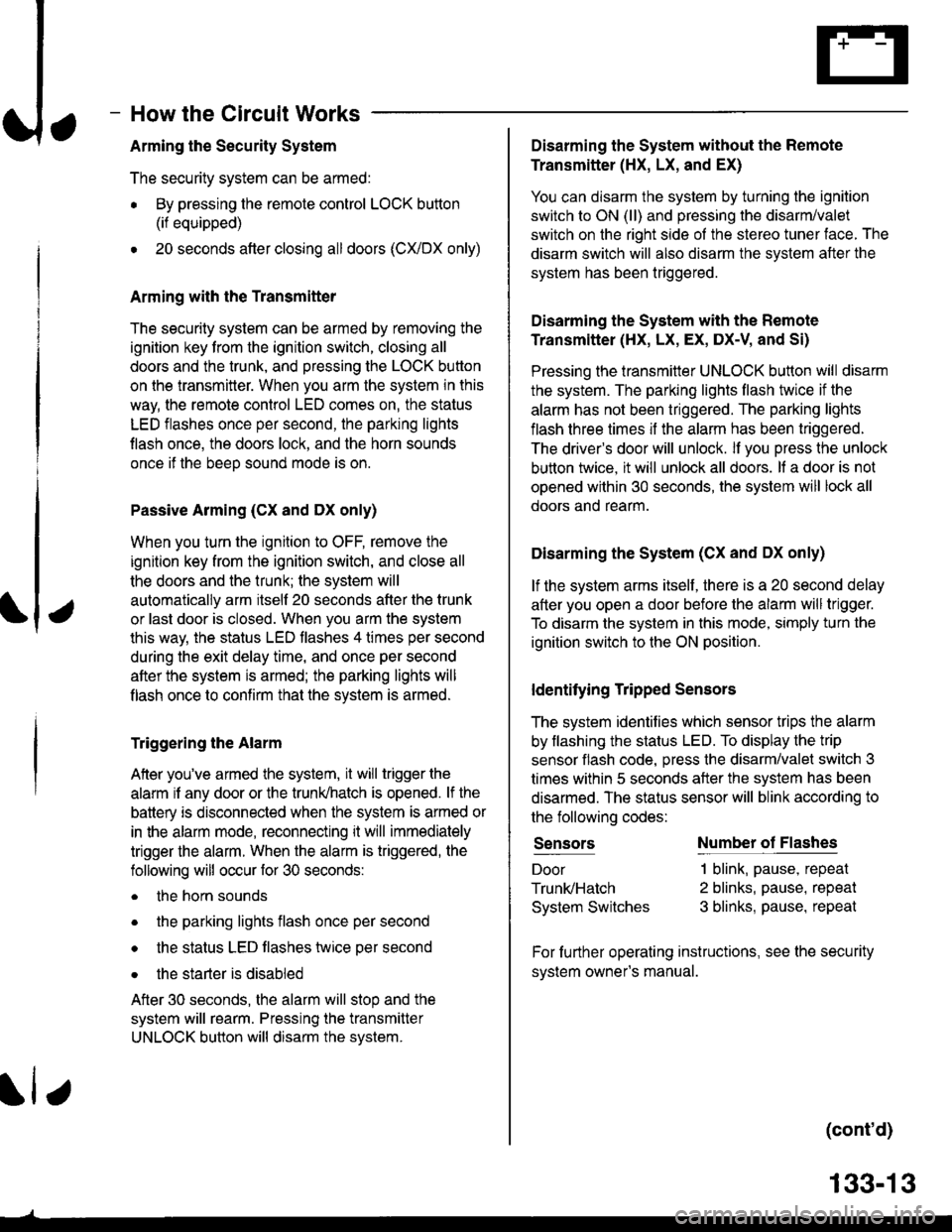
Arming the Security System
The security system can be armed:
r By pressing the remote control LOCK button
(if equipped)
. 20 seconds atter closing all doors (C)UDX only)
Arming with the Transmitter
The security system can be armed by removing the
ignition key from the ignition switch, closing all
doors and the trunk, and pressing the LOCK button
on the transmitter. When you arm the system in this
way, the remote control LED comes on, the status
LED flashes once per second, the parking lights
flash once. the doors lock. and the horn sounds
once if the beeo sound mode is on.
Passive Arming (CX and Dx only)
When you turn the ignition to OFF, remove the
ignition key from the ignition switch, and close all
the doors and the trunk; the system will
automatically arm itself 20 seconds after the trunk
or last door is closed. When you arm the system
this way, the status LED tlashes 4 times per second
during the exit delay time, and once per second
after the system is armed; the parking lights will
flash once to confirm that the system is armed.
Triggering the Alarm
Atter you've armed the system, it will trigger the
alarm if any door or the trunldhatch is opened. lf the
battery is disconnected when the system is armed or
in the alarm mode, reconnecting it will immediately
trigger the alarm. When the alarm is triggered, the
following will occur for 30 seconds:
. the horn sounds
o the parking lights flash once per second
. the status LED flashes hvice oer second
. the starter is disabled
After 30 seconds, the alarm will stop and the
system will rearm. Pressing the transmitter
UNLOCK button will disarm the svstem.
tlr
133-13
Disarming the System without the Remote
Transmitter (HX, LX, and EX)
You can disarm the system by turning the ignition
switch to ON (ll) and pressing the disarm/valet
switch on the right side ol the stereo tuner face. The
disarm switch will also disarm the svstem after the
system has been triggered.
Disarming the System with the Remote
Transmitter (Hx, Lx, Ex, DX-V, and Si)
Pressing the transmitter UNLOCK button will disarm
the system. The parking lights llash t\ivice if the
alarm has not been tnggered. The parking lights
flash three times if the alarm has been triggered.
The driver's door will unlock. lf you press the unlock
button twice, it will unlock all doors. lf a door is not
opened within 30 seconds, the system will lock all
doors and rearm.
Disarming the System (CX and DX only)
lf the system arms itself, there is a 20 second delay
after you open a door before the alarm will trigger.
To disarm the system in this mode, simply turn the
ignition switch to the ON position
ldentitying Tripped Sensors
The system identifies which sensor trips the alarm
by flashing the status LED. To display the trip
sensor flash code, press the disarm/valet switch 3
times within 5 seconds after the system has been
disarmed. The status sensor will blink according to
the followino codes:
SensorsNumber of Flashes
Door
TrunldHatch
System Switches
1 blink, pause, repeat
2 blinks, pause, repeat
3 blinks, pause, repeat
For further operating instructions, see the security
syslem owner's manual.
(cont'd)
Page 2068 of 2189
Security System (cont'd)
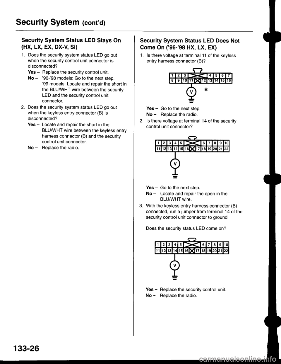
Security System Status LED Stays On
(HX, LX, EX, DX-V, Si)
1 . Does the security system status LED go out
when the security control unit connector is
disconnected?
Yes - Replace the security control unit.
No - '96-'98 models: Go to the next steD.'99 models: Locate and repair the short in
the BLUMHT wire between the security
LED and the security control unit
connector.
2. Does the security system status LED go out
when the keyless entry connector (B) is
disconnected?
Yes - Locate and repair the short in the
BLU,ryVHT wire behveen the keyless entry
harness connector (B) and the security
control unil connector.
No - Beplace the radio,
133-26
Security System Status LED Does Not
Come On ('96-'98 HX, LX, EX)
1 . ls there voltage at terminal 11 of the keyless
entry harness connector (B)?
Yes - Go to the next steo.
No - Replace the radio.
ls there voltage at terminal 14 of the security
control unit connector?
Yes - Go to the next steo,
No- Locate and repair the open in the
BLUMHT wire.
With the keyless entry harness connector (B)
connected, run a jumper from terminal 14 of the
security control unit connector to ground.
Does the securitv status LED come on?
Yes - Replace the security control unit.
No - Reolace the radio.
Page 2074 of 2189
Power Mirrors
- Without Defogger
r,-;;---j HEAIEF 1/ A/C FEIAY
I t uo s"" Po*", !f-----f Distribution, I
L_i:i:_J
UNDER-DASH
RELAYBOX
UNDER-OASHFUSE/RELAYBOX
I
I
I
I
I
BLK/BLU
10
BLK/BLU
-l
I
I
I
I
IJ
f,-G;---
I See Power
lF---t Distribution,
L_i:i'i_
rt;%,"
*'ii%.,
L vtEW 46
vlEw 22
'96-'98 modelsand all GX models
'99r00 modelsexcept GX
a-
c639
vlEW23
c656
POWERMIRBORswtTcHvtEw 33
See GroundDistribution,page 14-8.
LEFTMIRRORRIGHTMIRROR
G-t
BLU/BLK
('98 00mooets2't)15
BLU/ALK
LT GRN
G551
141
Page 2075 of 2189
How the Circuit Works
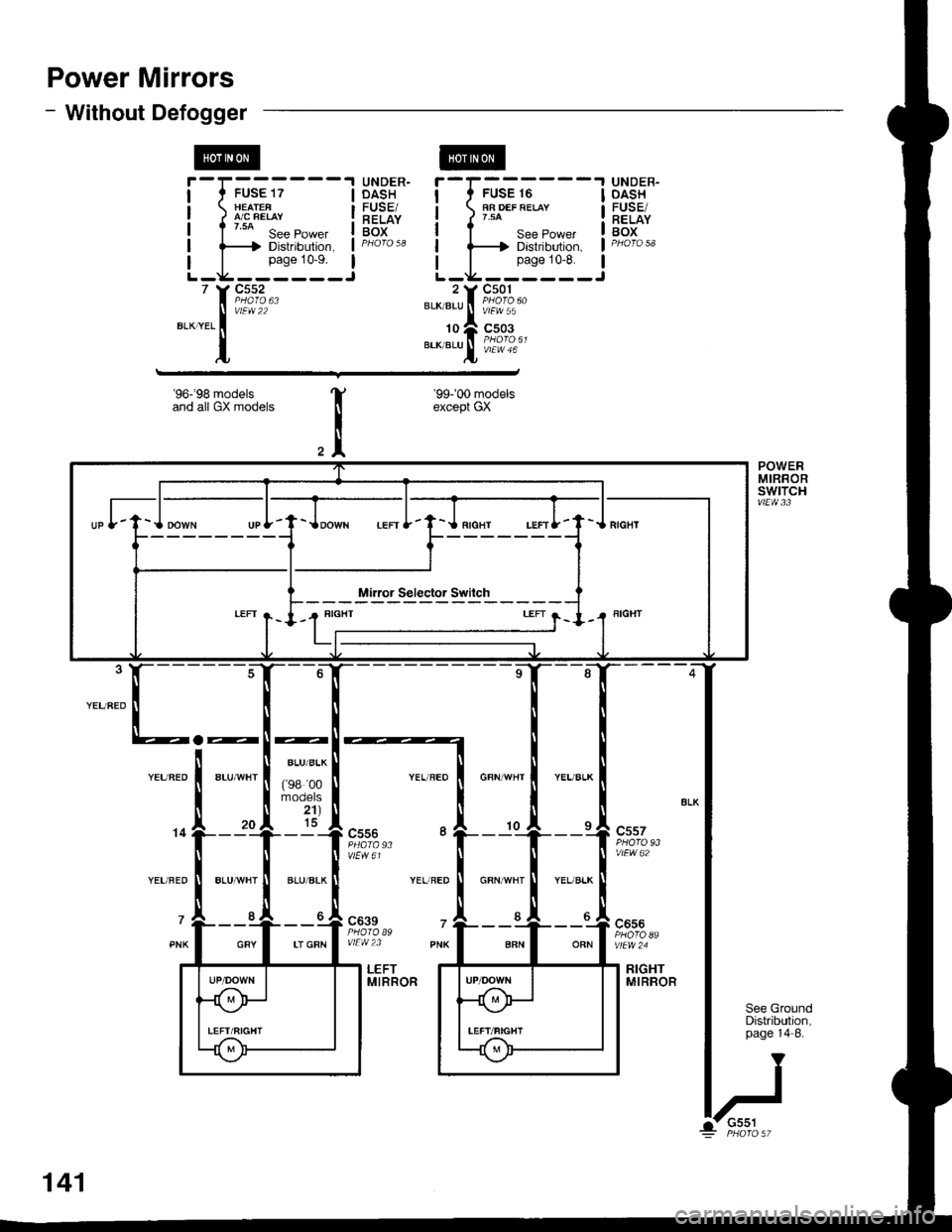
The two outside mirrors are controlled by the power
mirror switch. Each mirror has two reversible
motors: one motor moves the mirror up and down
and the other motor moves the mirror lett and right.
The power mirror switch contains four switches to
control mirror adjustment, and two switches to
select the left or right mirror With the ignition in ON
(ll), battery voltage is supplied to the power mirror
swrtch. The mirror selector switch directs voltage
from two of the direction switches to either the left
or the right mirror.
Mirror Up
When you press the "up" edge of the mirror
adjustment button, ground is supplied from one of
the up/down switch contacts to both mirrors; battery
voltage is supplied from the opposite up/down
switch contact through the mirror select switch. lf
the mirror select switch is in the left or right position,
battery voltage is supplied to the corresponding
mirror uo/down motor which then tilts the selected
mtrror uD.
Mirror Down
When you press the "down" edge of the mirror
adjustment button, battery voltage is supplied Irom
one of the up/down swilch contacts to both mirrors;
a ground is supplied from the opposite up/down
switch contact through the mirror select switch. lf
the mirror select switch is in the left or right position,
battery voltage is supplied to the corresponding
mirror up/down motor which then tilts the selected
mrrror oown.
Mirror Left
When you press the "|eft" edge of the mirror
adjustment button, battery voltage is supplied from
one of the lefuright switch contacts to both mirrors;
a ground is supplied from the opposite lefuright
switch contact through the mirror select switch. lf
the mirror select switch is in the left or right position,
battery voltage is supplied to the corresponding
mirror lefvright motor which then tilts the selected
mirror to the lett.
Mirror Right
When you press the "right" edge of the mirror
adjustment button, ground is supplied from one of
the lefvright switch contacts to both mirrors; battery
voltage is supplied from the opposite left/right switch
contact through the mirror select switch. lf the mirror
select switch is in the left or right position, battery
voltage is supplied to the corresponding mirror
lefuright motor which then tilts the selected mirror to
the right.
Refer to the Service Manual (Section 23, Electrical)
for speclfic tests of troubleshooting procedures
141-1