Page 1708 of 2189
Moonroof
1.
Switch Test
Carefully remove the switch from the driver's dash-
board lower cover {see page 23-205}.
Check for continuitv between the terminals in each
switch position according to the table.
Terminal
t*',*-----__\I234
ut-t-
OPENo--o
CLOSEo---o
TILTo--o
23-234
Motor Test
'1.Remove the headliner (see section 20).
Disconnect the 2P connector from the moonroof
motor.
Terminal side of male terminals
Check the motor by connecting power and ground
according to the table.
4. lf the motor does not run, replace it (see section 20).
NOTE: See Closing Force Check in section 20 for
motor clutch test.
\_____lTr1
Position
,l
OPENo@
CLOSE@
Page 1709 of 2189
Open/Close-Tilt/Close Switch Test
1. Remove the headliner (see section 20).
2. Disconnect the 2P and 4P connectors from the moon-
roof motor and the switch.
3. Check for continuity between the terminals in each
switch position according to the table.
Terminal side of male terminals
Terminal
*r*"-
-\123
CLOSE .* TILTo--oo---o
CLOSE ..--. OPENo--o
4. lf there is no continuity, adiust or replace the switch'
l-t
23-239
Page 1712 of 2189
Cruise Control
Gontrol Unit Input Test
SRS components are located in this area. Review the SRS component locations, precautions, and procedures in the SRSsection (24) before performing repairs or service.
1. Remove the driver's dashboard lower cover and knee bolster (see section 20).
2. Disconnect the l4P connector from the control unit.
3. Inspect the connector and socket terminals to be sure they are all making good contact.
lf the terminals are bent, loose, or corroded, repair them as necessary, and recheck the system.lf the terminals look OK, make the following inpul tests at the connecror.- lf any test indicates a problem, find and correct the cause, then recheck the system,- lf all the input tests prove OK, the control unit must be faulty; replace it.
14P CONNECTOR
CRUISE CONTROL UNIT
*i '99 00 models with A/T
23-242
GRN/WHT LT GRN/RED LT GRN/BI-K
8LU/GRN*
Wire side of female terminals
Page 1713 of 2189

)
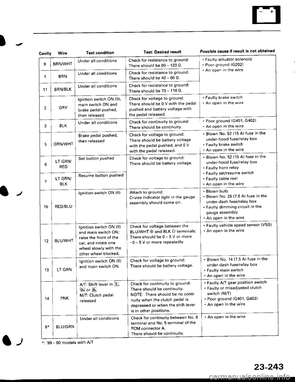
CavityWireTest conditionTest: Desired resultPossible cause if result is not obtained
BRNA/VHTUnder all conditionsCheck for resistance to ground:
There should be 80 - 120 O.
Fau lty actuator solenoid
Poor ground (G202)
An open in the wire
1BRNUnder all conditionsCheck for resistance to ground:
There should be 40 - 60 0.
11BRN/BLKUnder all conditionsCheck for resistance to ground:
There should be 70 - 110 0.
2GRY
lgn jtion switch ON (ll),
main switch ON and
brake pedal pushed,
then released
Check for voltage to ground:
There should be 0 V with the Pedal
pushed and battery voltage with
the pedal released.
'Faulty brake switch
. An open In the wlre
3BLKU nderall conditionsCheck for continuitY to groundl
There should be continuity
' Poor ground (G401, G402)
. An open in the wire
5GRNA,A/HT
Brake pedal pushed,
then released
Check for voltage to groundl
There should be batterY voltage
with the Pedal Pushed. and 0 V
with the pedal released
. Blown No. 52 (15 A) fuse in the
under-hood fuse/relaY box
. Faulty brake switch. An open in the wire
LT GRN/
RED
Set button pushedCheck for voltage to ground:
There should be batterY voltage.
Blown No. 52 (15 A) fuse in the
under-hood fuse/relaY box
Faulty horn relay
Faulty sevresume switch
Faulty cable reel
An open in the wire7LT GRN/
BLK
Resume button Pushed
10RED/BLU
lgnition switch ON (ll)Attach to ground:
Cruise indicator light in the gauge
assembly should come on.
Blown bulb
Blown No. 25 (7.5 A) fuse in the
under dash fuse/relay box
Faulty dimming circuit in the
gauge assemDly
An open in the wire
BLU,A/VHT
lgnition switch ON (ll)
and main swilch ON;
raise the front of the
car, and rotate one
wheel slowly with the
other wheel blocked.
Check for voltage between the
BLUMHT @ and BLK O terminals:
There should be 0- 5 V or more
-0- 5 V or more repeatedlY
. Faulty vehicle speed sensor {VSS)
. An open in the wire
LT GRN
lgnition switch ON (ll)
and main switch ON
Check for voltage to ground:
There should be batterY voltage.
Blown No. 14 (7.5 A)fuse in the
under-dash luse/relaY box
Faulty main switch
An open in the wire
14PNK
A,T: Shift lever in E,
ojorE
M/T: Clutch pedal
released
Check for continuity to ground:
There should be continuity.
NOTE: There should be no conti-
nuity when the clutch Pedal is
depressed or when the shift lever
is in other positions.
Faulty A/f gear position switch
Faulty or misadjusted clutch
switch (M/T)
Poor ground (G401, G402)
An open in the wire
BLU/GRN
Under all conditionsCheck for continuity between No. I
terminal and No. 5 terminal of the
PCM connector A.
There should be continuity
. An open in the wire
*: '99 - 00 models with A,/Tl-,
23-243
Page 1714 of 2189

Cruise Gontrol
3.
1.
2.
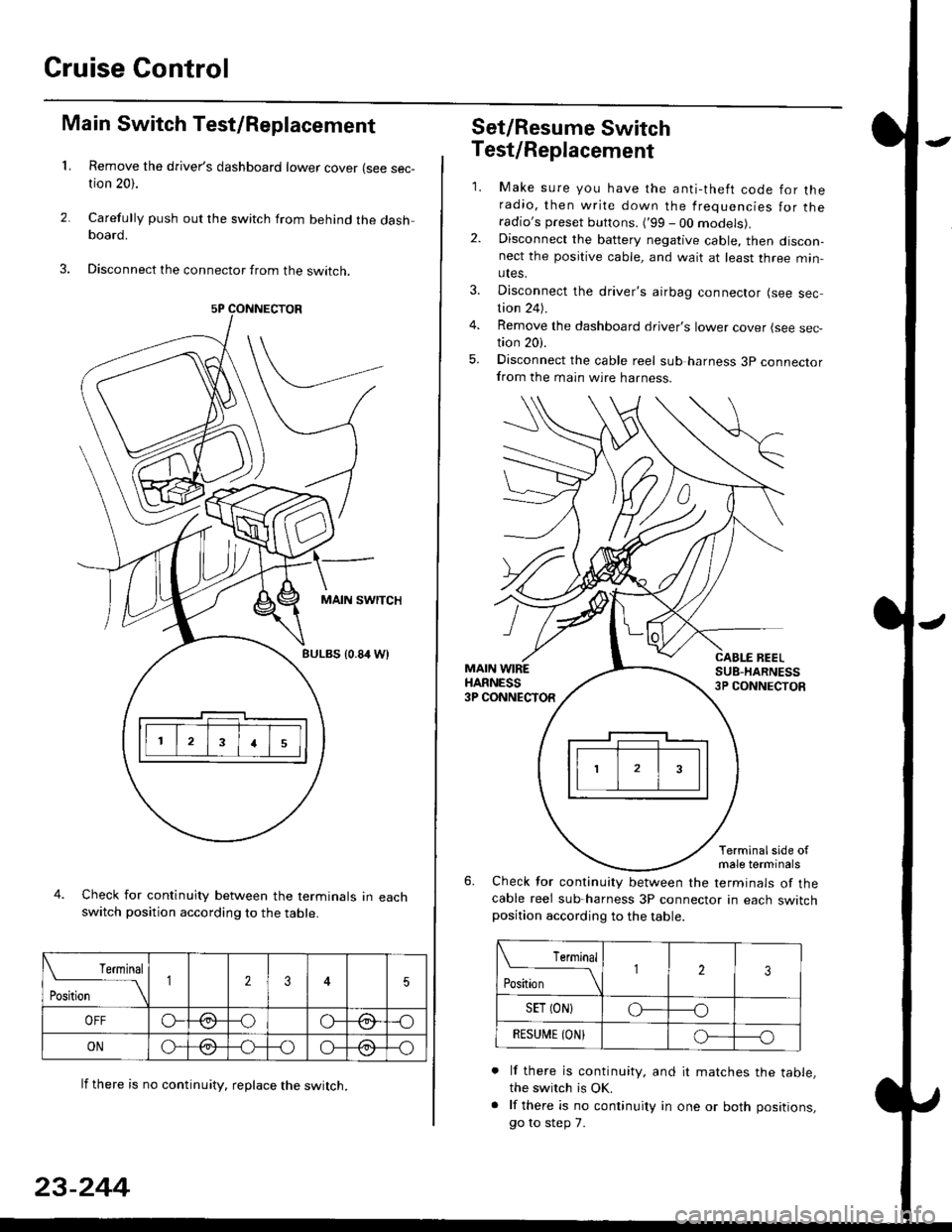
Main Switch Test/Replacement
Remove the driver's dashboard lower cover (see sec-tion 20).
Carefully push out the switch from behind the dashboard.
Disconnect the connector from the swtrcn.
MAIN SWITCH
BULBS {0.84 Wt
Check for continuity between the terminals in eachswitch position according to the table.
lf there is no continuity. reDlace the switch.
4.
Terminal
r**
--\235
OFFo--oGa\-o\:./\a/
ONo-/a-oo--o\:/\:/
23-244
Set/Resume Switch
5.
Test/Replacement
2.
1.
MAIN WIREHARNESS3P CONNECTOR
Make sure you have the anti-theft code for theradio, then write down the frequencies for theradio's preset buttons. ('99 - 00 models).Disconnect the battery negative cable, then discon-nect the positive cable, and wait at least three min-utes.
Disconnect the driver's airbag connector (see sec-tion 24).
Remove the dashboard driver's lower cover (see sec,tion 20).
Disconnect the cable reel sub harness 3p connectorfrom the main wire harness.
CABLE BEELSUB-HARNESS3P CONNECTOS
Terminalside ofmale terminals
Check for continuity between the terminals of thecable reel sub-harness 3P connector in each switchposition according to the table.
L Terminal
Position123
SET (ON}o----o
BESUi,|E IONIo-----o
lf there is continuity, and it matches the table,the switch is OK.
lf there is no continuity in one or both positions,
go to step 7.
Page 1715 of 2189
7. Remove th€ two screws, then remove the switch'
Check for continuity between the terminals in switch
position according to the table.
Terminal
t"-"t*
-\23
SET (ON)o--o
RESUI\4E {ON}o----o
lf there is continuity, and it matches the table,
replace the cable reel.
lf there is no continuity in one or both positions,
reDlace the switch.
8.
SET/NESUME
l-l
23-245
11.
q
10.
12.
lf all tests prove OK, reconnect the cable reel and
cable reel sub-harness connector, then reinstall the
steering column covers
Reconnect the driver's airbag connector. and rein-
stall the access panel on the steering wheel.
Reconnect the battery positive cable, then the nega-
tive cable.
After connecting the airbag connectors, confirm
proper system operation; Turn the ignition switch ON
(ll); the SRS indicator light should come on for about
six seconds and then go off.
Enter the anti-theft code for the radio, then enter the
customer's radio station presels {'99 -00 models)'
Page 1716 of 2189
Cruise Control
Brake Switch Test
1. Disconnect the 4P connector from the switch.
4P CONNECTOR
BRAKEPEDAL
Check for continuity between the terminals accord-
ing to the table.
Terminal
t"r. ** \
123
RELEASEDo---o
DEPRESSEDoo
3. lf necessary. replace the switch or adjust pedal
height (see sectionl9).
23-246
clutch switch Test (M/Tl
1. Disconnect the 2P connector from the switch.
swtTcH
2. Check for continuity between the terminals accord-
ing to the table.
Terminal
.***aal
-\I2
RELEASED
DEPRESSEDo--o
3. lf necessary, replace the switch or adiust pedal
height (see section '12).
Page 1717 of 2189

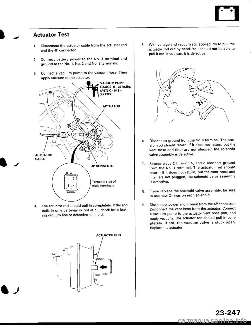
)Actuator Test
't.Disconnect the actuator cable from the actuator rod
and the 4P connector.
Connect battery power to the No 4 terminal and
ground to the No. 1, No. 2 and No. 3 terminals.
Connect a vacuum pump to the vacuum hose Then
apply vacuum to the actuator.
2.
VACUUM PUMPGAUGE,0 - 30 in.Hg.
{A973X - 041 -
xxxxxl
ACTUATOR
,lP CONNEcToR
Terminalside o{male termrnals
4. The actuator rod should pull in completely. lf the rod
pulls in only pan-way or not at all' check for a leak-
ing vacuum line or defective solenoid.
ACTUATOF ROD
l-t
23-247
5. With voltage and vacuum still applied, try to pull the
actuator rod out by hand. You should not be able to
oull it out. ll you can, it is defective
1.
Disconnect ground from the No.3 terminal. The actu-
ator rod should return lf it does not return, but the
vent hose and filter are not plugged, the solenoid
valve assembly is defective.
Repeat steps 2 through 5, and disconnect ground
from the No. 1 terminal. The actuator rod should
return. lI it does not return, but the vent hose and
filter are not plugged. the solenoid valve assembly
is defective.
It you replace the solenoid valve assembly, be sure
to use new O-rings on each solenoid.
Disconnect power and ground from the 4P connector.
Disconnect the vent hose from the actuator. Connect
a vacuum pump to the actuator vent hose port, and
apply vacuum. The actuator rod should pull in com-
pletely. lf not, the vacuum valve is stuck open.
Replace the actuator'
8.