1996 HONDA CIVIC Rear main
[x] Cancel search: Rear mainPage 2121 of 2189
Gonnector Views (conrd)
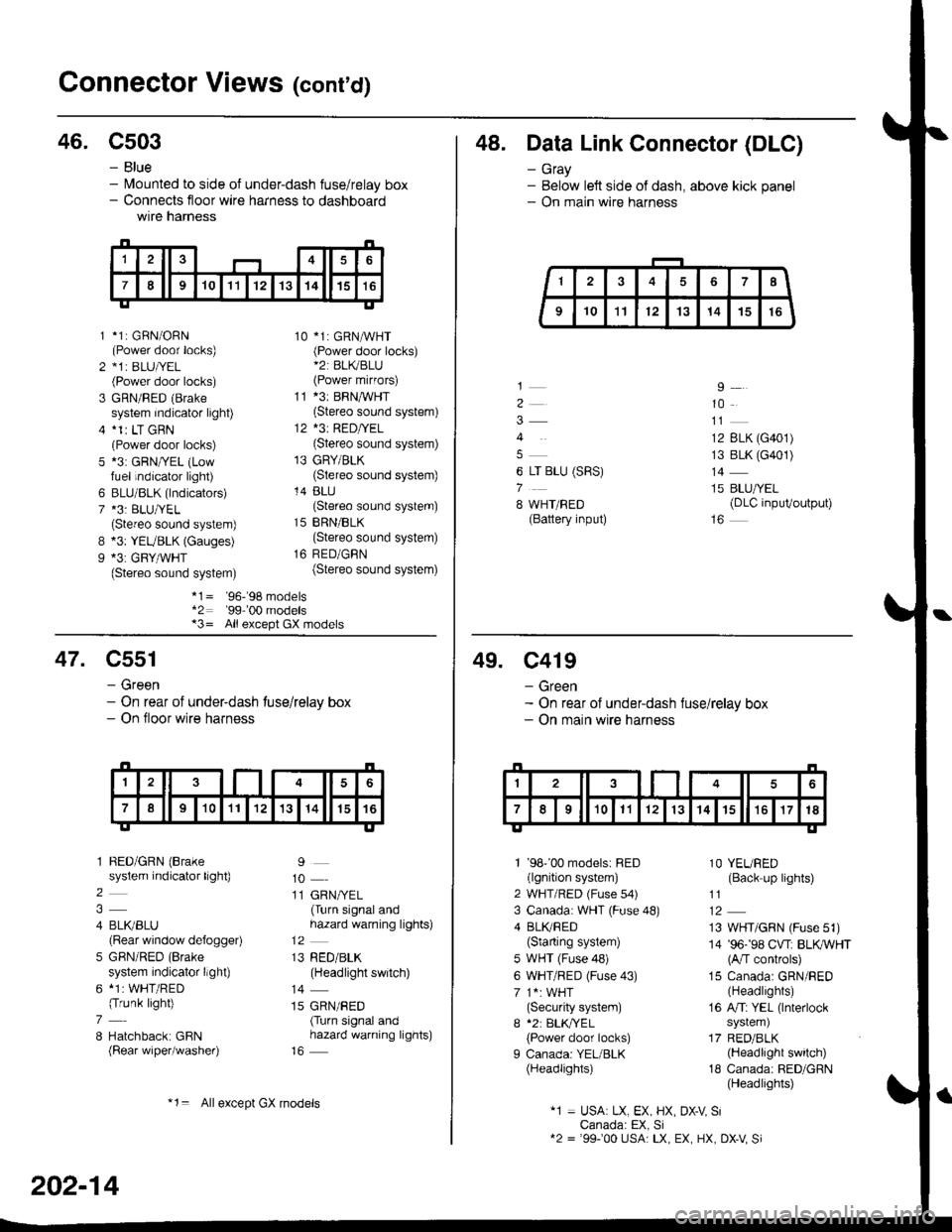
46. C503
B
9
*1: GBN/ORN(Power door locks)*1r BLU|/EL(Power door locks)
GRN/RED (Brake
system indicator light)*1r LT GRN(Power door locks)*3: GRN/YEL (Lowfuel indicator light)
BLU/BLK (lndicators)*3: BLU/YEL(Stereo sound system)*3: YEUBLK (Gauges)*3: GRY/WHT(Stereo sound system)
10 *1: GRNAVHT(Power door locks)*2: BL(BLU(Power mirfors)
11 *3: BRNMHT(Stereo sound system)
12 *3: RED/YEL(Stereo sound system)
13 GRY/BLK(Stereo sound system)
14 BLU(Stereo sound system)
15 BRN/BLK(Stereo sound system)
16 RED/GBN(Stereo sound system)
- Blue- lvlounted to side of under-dash fuse/relay box- Connects floor wire harness to dashboardwtre narness
1
2
3
5
6
7
*1= '96-'98 models*2: '99-'00 models*3= All except GX models
48. Data Link Connector (DLC)
- Gray- Below left side of dash, above kick panel- On main wire harness
4
6 LT BLU (SRS)
7
8 WHT/BED(Battery input)
9
10
12 BLK (G401)
13 BLK (G401)
14
15 BLU/YEL(DLC inpuVoutput)
47. C551
- Green- On rear of under-dash tuse/relay box- On floor wire harness
1 BED/GRN (Brake
system indicator light)
2
4 BLI(BLU(Rear window defogger)
5 GBN/RED (Brake
system indicator llght)
6 *1: WHT/RED(Trunk light)
7
8 Hatchback: GBN(Rear wiper/washer)
9
10
11 GRN/YEL(Turn signal andhazard warning lights)
13 RED/BLK(Headlight switch)
14
15 GRN/RED(Turn signal andhazard warning lights)
202-14
*1= Allexcept GX models
49. C419
- Green- On rear of under-dash fuse/relay box- On main wire harness
1 '98''00 models: RED(lgnition system)
2 WHT/RED (Fuse s4)
3 Canada: WHT (Fuse 48)
4 BLI(RED(Starting system)
5 WHT (Fuse 48)
6 WHT/RED (Fuse 43)
7 1*: WHT(Security system)
I *2: BLK,TYEL
{Power door locks)
I Canada: YEL/BLK(Headlights)
1O YEURED(Back up lights)
11
13 WHT/GRN (Fuse 51)
14 '96-'98 CVT: BLKWHT(A/T controls)
15 Canada: GRN/RED(Headlights)
16 A/Ti YEL (lnterlock
system)
17 RED/BLK(Headlight switch)
18 Canada: RED/GRN(Headlights)
"1 = USA: LX, EX, HX, DX-V SiCanada: EX, Si12 = '99100 USA: LX, EX, HX, DX-V Si
Page 2122 of 2189
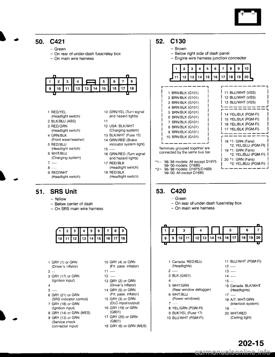
-50. c421
- Green- On rear of under-dash fuse/relay box- On main wire harness
I
l RED/YEL(Headlight switch)
2 BLIVBLU (ABS)
3 RED/GRN(Headlight switch)
4 GFIN/BLK(Front wiper/washer)
5 FED/BLU(Headlight swrtch)
6 WHT/BLU(Charging systern)
7
9 REDAVHT(Headlight switch)
10 GRN/YEL (Turn signaland hazard lights)
11
12 USA: BLKAVHT(Charging system)
13 BLKryVHT (Fuse 15)
14 GRN/RED (Brake
indicator system light)
16 GRN/RED (Turn signaland hazard lights)
17 BED/BLK(Headlight switch)
18 RED/BLK(Headlight switch)
52. C130
- Brown- Below right side ot dash panel- Engine wire harness junction connector
T---------"1
1 8RN/BLK (G101)
2 BRN/BLK (G101)
3 BRN/BLK (G101)
4 BRN/BLK (G101)
5 BRN/BLK (G101)
6 BRN/BLK (G101)
7 BRN/BLK (G101)
I BRN/BLK (G101)
9 BRN/BLK (G101)
10 BBN/BLK (G101)
L---------J
Terminals grouped together areconnected by the sarre bus bar.
*1= 96- 98 models: All except D16Y5'99-'00 models: D1685*2= 96-98 models: D16Y5/D1685'99- 00r All except D1685
11 BLUMHT (VSS)
12 BLU,ryVHT (VSS)
13 BLU,^/VHT (VSS)L_-_____--Jr---------'1
14 YEL/BLK (PGl\4-Fl)
15 YEL/BLK (PGr\4'Fr)
16 YEUBLK (PGI\4,FI)
17 YEUBLK (PGr\4,Fr)L______---JT----------118 *1: GRN (Fans)*2: YEUBLU (PGM-Fl)
19 *1: GRN (Fans).2: YEUBLU (PGM-Fl)
20 *1: GRN (Fans).2: YEUBLU (PGM-Fl)_______--J
51. SRS Unit
- Yellow- Below center oJ dash- On SRS marn wire harness
1 GFY (1) or GRN(Drivefs nflator)
2
3 GRY (17) or GRN(lgn tion input)
6 GRY (21) or GRN(SRS indicalor control)
7 GRY (18) or GRN(lgnition nput)
8 GBY (14) or GRN (MES)
9 GBY (13) of GRN(Service checkconnector input)
10 GRY (4) or GRN(Frt. pass. inflato4
11
13 GBY (2) or GRN(Drivefs nflator)
14 GBY (5) or GRN(Frt. pass. inflator)
15 GRY (3) or GRN(DLC input/output)
16 GRY (19) or GRN(G801)
17 GRY (20) or GRN(G801)
1B GRY (6) or GRN (MES)
13678
10Il12131415't7't8
53. C420
- Green- On rear of under-dash fuse/relay box- On main wire harness
1 Canadar RED/BLU(Headlights)
2
3 8LK (G401)
5 WHT/GRN(Rear window defogger)
6 WHT/BLU(Power windows)
7
8 YEL/GRN (PGM-FD
I BLK//EL (Fuse 17)
1O BLUAVHT (PGM,FI)
1 1 BLUMHT (PGI,4-FI)
14
16 Canada: BLKAVHT(Headlights)
18 A/Tr WHT/GRN(lnterlock system)
19
20 WHT/RED(Ceiling light)
202-15
Page 2127 of 2189
Connector Views (cont'd)
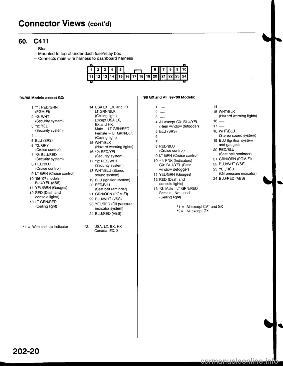
60. c411
- Blue- Mounted to top ol under-dash fuse/relay box- Connects main wire harness to dashboard harness
'95198 Models excepl GXI
1 *1: RED/GRN(PGrvr-FD
2 A2: WHT(Security system)
(Security system)
4
5 BLU (SRS)
6 *2r GRY(Cruise control)
7 *2: BLU/RED(Security system)
8 RED/BLU(Cruise control)
9 LT GRN (Cruise control)
10 '96-�97 models:BLU/YEL (ABS)
11 YEUGRN (Gauges)
12 RED (Dash andconsole lights)'13 LT GRN/RED(Ceiling light)
*1 = With shitt-up indicator
14 USA LX, EX, and HX:LT GRN/BLK
{Ceiling light)Except USA LX,EX and HX:ftrale - LT GRN/REDFemale - LT GRN/BLK(Ceiling light)
15 WHT/BLK(Hazard warning lights)
16 *2: RED|YEL(Security system)
17 *2: REDA/VHT(Security system)
18 WHT/BLU (Stereo
sound system)
19 BLU (lgnition system)
20 RED/BLU(Seat bett reminder)
21 GRN/OBN (PGN4 FD
22 BLUAVHT (VSS)
23 YEURED (Oil pressure
indicator system)
24 BLU/RED (ABS)
USA: LX: EX, HXCanadar EX, Si
202-20
'98 GX and All '99-'00 Models:
1
2
4 All except GX: BLU/YEL(Rear window defogger)
5 BLU (SRS)
7
B RED/BLU(Cruise control)
9 LT GRN {Cruise control)
10 *1: PNK (lnd cators)GX: BLU/YEL (Bear
window defo9ger)
1l YEL/GBN (Gauges)
12 RED (Dash andconsole lights)
13 *2: Male - LT GRN/REDFemale - Not used(Ceiling light)
14
15 WHT/BLK(Hazard warning lights)
18 WHT/BLU(Stereo sound system)
19 BLU (lgnition systemano gaugesl
20 RED/BLU(Seat bell reminder)
21 GRN/ORN (PG[,4-Fl)
22 BLU,ryVHT O/SS)23 YEURED(Oil pressure indicator)
24 BLU/RED (ABS)
*1 = Allexcept CW and GX*2= All except GX
Page 2130 of 2189
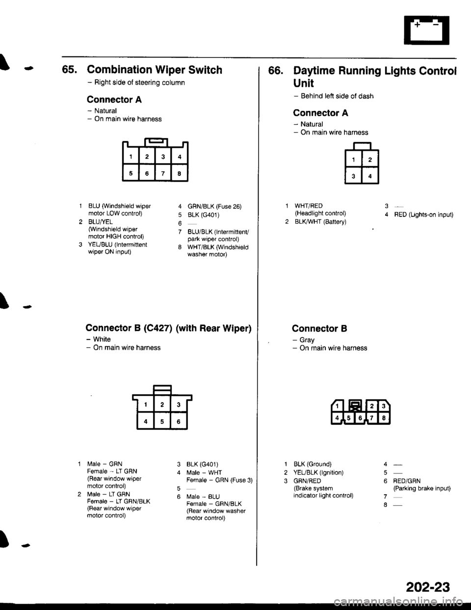
65. Combination Wiper Switch
- Right side ot steering column
Connector A
- Natural- On main wire harness
1BLU (Windshield wipermotor LOW conkol)
BLU/YEL(Windshield wipermotor HIGH control)
YEUBLU (lntermittentwiper ON input)
lilale - GRNFemale - LT GRN(Rear window wipermotor conkol)
lrale - LT GRNFema|e _ LT GRN/BLK(Rear window wipermotor control)
4 GnN/BLK (Fuse 26)
5 BLK (G401)
7 BLU/BLK(lntermittenvpark wiper control)
8 WHT/BLK (Windshieldwasher motor)
BLK (G401)
Male - WHTFemale - GRN (Fuse 3)
Male - BLUF€male _ GRN/BLK(Rear window washermotor control)
\
Connector B (C4271 (with Rear Wiper)
- White- On main wire harness
3
5
6
)
I3
68
13
4
66. Daytime Running Lights Control
Unit
- Behind left side ol dash
Connector A
- Natural- On main wire
WHT/RED(H€adlight control)
BLKAVHT (Battery)RED (Lights-on input)
Connector B
- Gray- On main wire harness
narness
ffi
31
2
1
2
3
BLK (Ground)
YEUBLK (lgnition)
GRN/RED(Brake systemindicator light conkol)
RED/GRN(Parking brake input)
4
5
6
7
8
202-23
Page 2139 of 2189
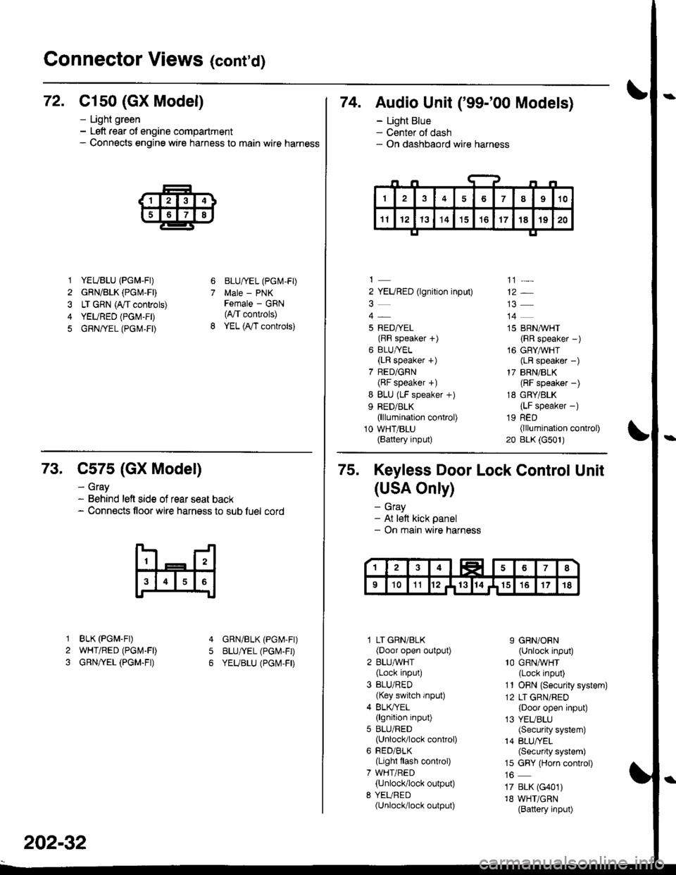
Connector Views (cont'd)
72. C1s0 (GX Model)
1 YEUBLU (PGM-FI)
2 GRN/BLK (PGM.FD
3 LT GRN (A/t controls)
4 YEURED (PGM-FD
5 GRN/rEL (PG|\,1-FD
- Light green- Left rear of engine compartment- Connects engine wire harness to main wire harness
6
7
BLU/IEL (PGM-FD
Male - PNKFemale - GRN(4,/T convols)
YEL (A,/T controls)
74. Audio Unit ('99-'00 Models)
- Light Blue- Center ol dash- On dashbaord wire harness
2 YEURED (lgnition input)
5 RED/YEL(RF speaker f)
6 BLU/YEL(LR speaker +)
7 RED/GRN(BF speaker +)
I BLU (LF speaker +)
9 RED/BLK(lllumination control)
10 WHT/BLU(Battery input)
']]]-
12*
14
15 BRN,^/VHT
{RR speaker -)
16 GRYAVHT(LR speaker -)
17 BRN/BLK(RF speaker -)
18 GRY/BLK
{LF speaker -)
19 RED(lllumination control)
20 BLK (G501)
73. C575 (GX Model)
BLK (PGM.FD
WHT/RED (PGI\4-FD
GRN/YEL (PGM.FI)
- Gray- Behind left side of rear seat back- Connects floor wire harness to sub luel cord
5
1
2
3
GRN/BLK (PGr\4-Fr)
BLU/YEL (PGI\'-FD
YEUBLU (PGI\,4,FD
202-32
75. Keyless Door Lock Control Unit
(USA Only)
- Gray- At lett kick panel- On main wire harness
l LT GRN/BLK(Door open output)
2 BLU,ryVHT(Lock input)
3 BLU/RED(Key switch input)
4 BLK/YEL(lgnition input)
5 BLU/RED(Unlock/lock control)
6 FED/BLK(Light flash control)
7 WHT/RED(Unlock/lock output)
8 YEURED(Unlock/lock output)
9 GRN/ORN(Unlock input)'10 GRNA/VHT(Lock input)
11 ORN {Securiiy system)
12 LT GRN/RED
{Door open input)
13 YEUBLU(Security system)
14 BLU/YEL(Security system)
15 GRY (Horn control)
17 BLK (G401)
18 WHT/GRN(Battery input)
Page 2140 of 2189
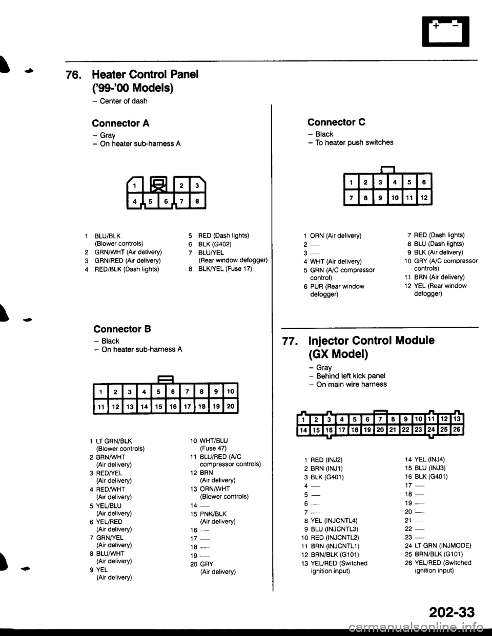
76. Heater Control Panel
('99100 Models)
- Center of dash
Conneclor A
- Gray- On heater sub-harness A
BLUi BLK(Blower controls)
GRNAVHT (Air delivery)
GRN/RED (Air delivery)
RED/BLK (Dash lights)
Connector B
- Black- On heater sub-harness A
7
8
1
4
RED (Dash lights)
BLK (G402)
BLUfYEL(Rear window defogg€0
BLK,TYEL (Fuse 17)
\
)
1 LT GRN/BLK(Blower controls)
2 BRN,A/VHT(Air delivery)
(Air delivery)
4 REDA/VHT(Air delivery)
5 YEUBLU(Air delivery)
6 YEURED(Air delivery)
7 GRN/YEL(Air delivery)
8 BLU,ryVHT(Air delivery)
9 YEL
{Air delivery)
1O WHT/BLU(Fuse 47)
11 BLU/RED WCcompressor controls)
12 BRN(Air delivery)
13 ORNAVHT(Blower controls)
14 -
15 PN(BLK(Air delivery)
16 _
19 _
20 GRY(Air delivery)
Connector C
- Black- To heater push switches
1 ORN (Air delivery)
2
4 WHT (Air delivery)
5 GRN (ry'C compressorcontrol)
6 PUR (Roar windowdelogge4
7 RED (Dash lights)
8 BLU (Dash lights)
I BLK (Air delivery)
10 GRY (Ay'C compressorcontrols)
1'1 BRN (Air delivery)
12 YEL (Rear window
defogge0
77. Injector control Module
(GX Model)
- Gray- Behind left kick panel- On main wire harness
1 RED (rNJ2)
2 BRN (rNJl )3 BLK (G401)
4_
8 YEL (TNJCNTL4)
9 BLU (TNJCNTL3)
1o RED (tNJCNTL2)
11 BRN 0NJCNTL1)12 BRN/BLK (G101)
13 YEURED (Switched
ignition input)
14 YEL (tNJ4)
15 BLU (rNJ3)
16 BLK (G401)
19 -
20-
21
24 LI GRN (INJMODE)
25 BRN/BLK (Gr 01)
26 YEURED (Switched
ignition input)
202-33
Page 2157 of 2189
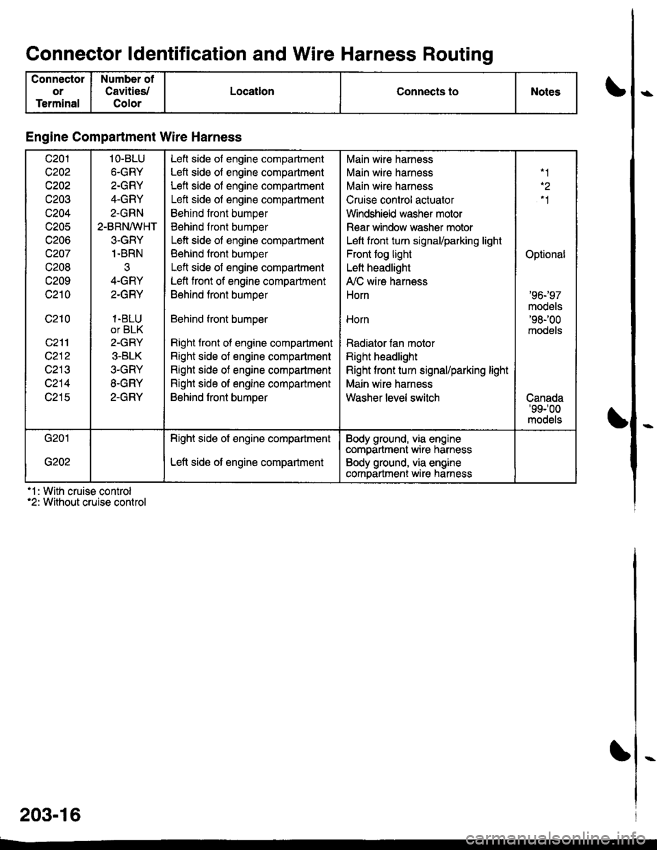
Connector ldentification and Wire Harness Routino
Connector
or
Terminal
Number of
Cavities/
Color
LocatlonConnects toNotes
Engine Compartment Wire Harness
c201
c202
c202
UZUJ
c204
c205
c206
c207
c208
c209
c210
c210
c212
c213
c214
c215
1O-BLU
6.GRY
2.GRY
4-GRY
2-GRN
2-BRN/VVHT
3-GRY
1.BRN
q-u11 r
2.GRY
1-BLU
or BLK
2-GRY
3-BLK
3-GRY
8.GRY
2-GRY
Lefl side of engine compartment
Left side of engine compartment
Left side ol engine compartment
Left side of engine compartment
Behrnd front bumper
Behind front bumper
Left side of engine compartment
Behind front bumper
Left side of engine compartment
Left front of engine compartment
Behind front bumoer
Behind front bumoer
Right front of engine compartment
Right side ot engine compartment
Right side of engine compartmont
Right side of engine compartment
Behind front bumoer
Main wire harness
Main wire harness
Main wire harness
Cruise control actuator
Windshield washer motor
Rear window washer motor
Left front turn signal/parking light
Front tog light
Left headlight
A,/C wire harness
Horn
Horn
Radiator fan motor
Right headlight
Right tront turn signal/parking light
Main wire harness
Washer level switch
'1
"1
Optional
'96-'97
models'98-'�00
models
Canada'99r00
models
G201
G202
Right side of engine compartment
Left side ot engine compartment
Body ground, via enginecompartment wire harness
Body ground, via engine
comDartment wire harness
'1 : With cruise control'2: Without cruise control
203-16
Page 2168 of 2189
)\
) -,
.'
'1: With shift-up indicator or cruise control system ('96-'97 models)
With cruise control system ('98-'00 models)
.2: '96198 models.3: '99-'00 models
c5o9 csrr c510 c515
13 1c517
DISHAOABD w|REIIARNESS
Connector
or
Terminal
Number of
Cavities/
Color
LocationConnects toNotes
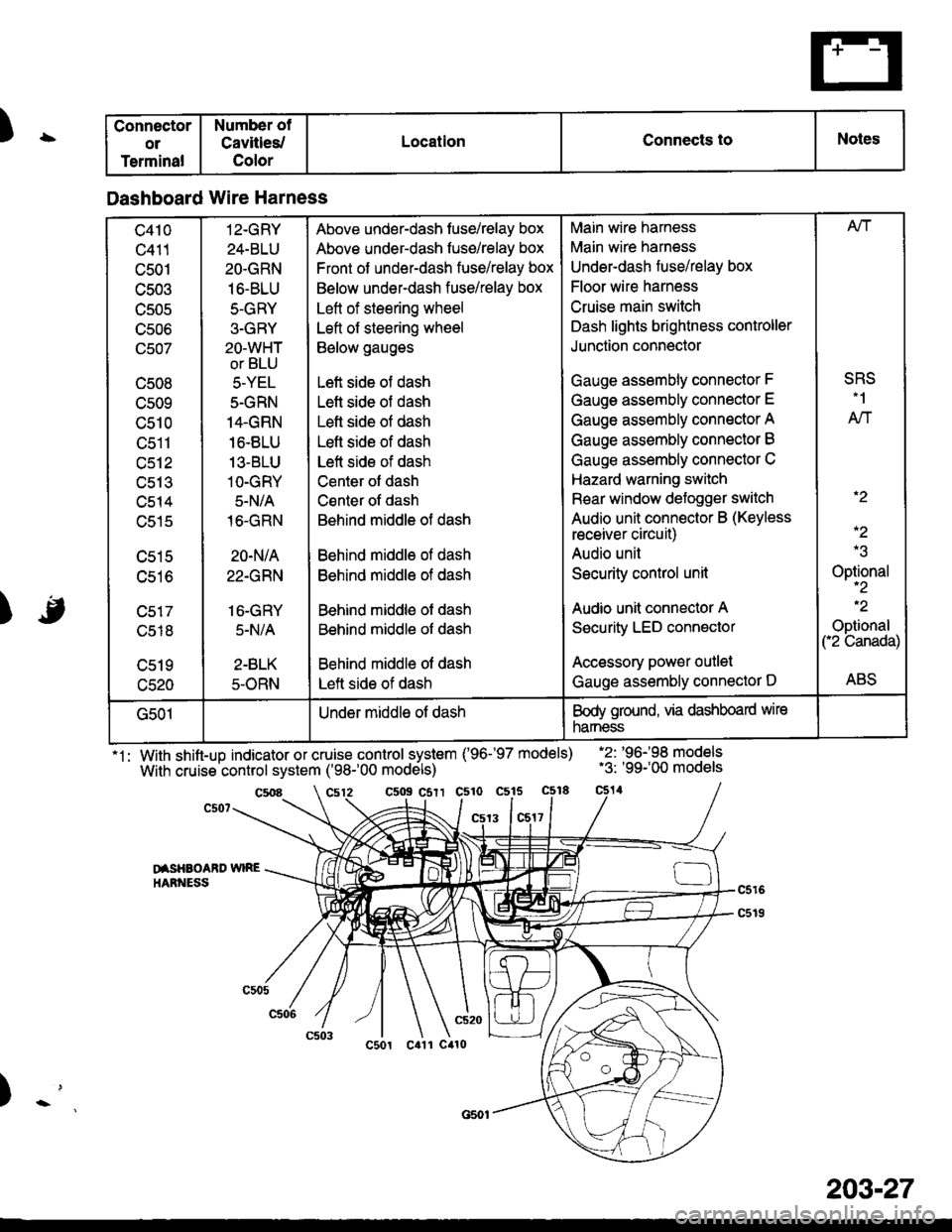
Dashboard Wire Harness
c410
c411
c501
c503
TJJUC
UCUO
(Jcu/
c508
cs09
c510
tJctl
c512
uc t.t
c514
c515
c516
c518
c520
12-GRY
24-BLU
2O.GRN
16-BLU
5-GRY
3-GRY
2O-WHT
or BLU
5-YEL
5-GRN
14.GRN
16.8LU
13-BLU
1O-GRY
5-N/A
16-GRN
20-N/A
22.GRN
16-GRY
5.N/A
2-BLK
5-ORN
Above under-dash fuse/relay box
Above under-dash fuse/relay box
Front of under-dash fuse/relay box
Below under-dash fuse/relay box
Left of steering wheel
Left of steering wheel
Below gauges
Left side of dash
Lett side of dash
Left side of dash
Lefl side of dash
Left side of dash
Center ot dash
Csnter of dash
Behind middle of dash
Behind middle ol dash
Behind middle of dash
Behind middle of dash
Behind middle of dash
Behind middle of dash
Left side of dash
Main wire harness
Main wire harness
Underdash fuse/relay box
Floor wire harness
Cruise main switch
Dash lights brightness controller
Junction connector
Gauge assembly connector F
Gauge assembly connector E
Gauge assembly connector A
Gauge assembly connector B
Gauge assembly connector C
Hazard warning switch
Rear window defogger switch
Audio unit connector B (Keyless
receiver circuit)
Audio unil
Security control unit
Audio unit connector A
Security LED connector
Accessory power outlet
Gauge assembly connector D
Afi
SRS.1
AN
.2
-2
Optional-2
.2
Optional("2 Canada)
ABS
G501Under middle of dashBody ground, via dashboard wire
narness
203-27