1996 HONDA CIVIC Park switch
[x] Cancel search: Park switchPage 1512 of 2189
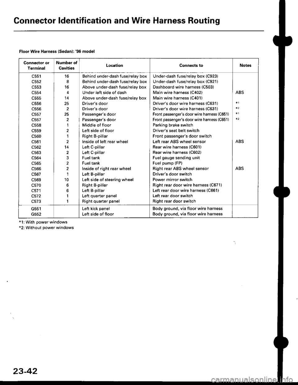
Gonnector ldentification and Wire Harness Routing
Connector ol
Terminal
Number of
CavitiesLocationConnects toNotes
c553
c554
c556
c557
c557
c558
c559
c560
c561
c562
c563
c564
c565
c566
c567
L5bY
c570
c511
c572
c513
6
14
25
2
25
'|
1
2't4
1'10
6
6
I
1
Behind underdash fuse/relay box
Behind under-dash fuse/relay box
Above under-dash fuse/relay box
Under left side of dash
Above under-dash fuse/relay box
Drlver's door
Driver's door
Passenger's door
Passenger's door
Middle of floor
Left side of floor
Right B-pillar
lnside of left rear wheel
Left C-pillar
Left C-pillar
Fuel tank
Fuel tank
Inside of right rear wheel
Left B-pillar
Left side of steering wheel
Right B-pillar
Left B-pillar
Left quarter panel
Right quarter panel
Under-dash fuse/relay box {C923)
Under-dash fuse/relay box (C921)
Dashboard wire harness (C503)
Main wire harness (C402)
Main wire harness (C401)
Driver's door wire harness (C631)
Driver's door wire harness (C631)
Front passenger's doorwire harness (C651)
Front passenge/s doorwire harness (C651)
Parking brake switch
Driver's seat belt switch
Front passenger's door switch
Left rear ABS wheel sensor
Rear wire harness (C601)
Rear wire harness (C602)
Fuel gauge sending unit
Fuel pump {FP)
Right rear ABS wheel sensor
Driver's door switch
Power mirror switch
Right rear door wire harness (C671)
Left rear door wire harness (C661)
Left rear door switch
Right rear door switch
ABS
ABS
ABS
G552
Left kick panel
Left side of floor
Body ground, via floor wire harness
Body ground, via floor wire harness
Floor Wire Harness lSedanl: '96 model
*l:With power windows*2; Without power windows
23-42
Page 1514 of 2189
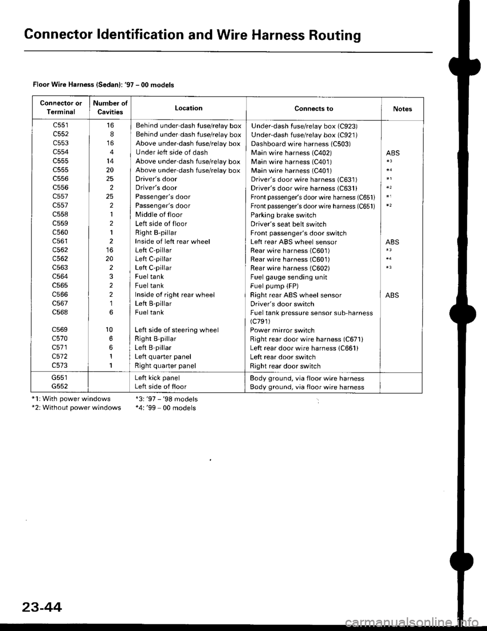
Gonnector ldentification and Wire Harness Routing
Floor Wire Harness (Sedanl: '97 - 00 models
Connector or
Terminal
Number of
CavitiesLocationConnects toNotes
c552
c553
c554
c555
c556
c557
c557
c558
c559
c560
c56'l
c562
c563
c564
c566
c568
c569
c570
c571
c572
16
8
14
20
25
2
2
1
2
1
20
2
2
2
1
l0
1
1
Behind under-dash fuse/relay box
Behind under dash fuse/relay box
Above under-dash fuse/relay box
Under left side of dash
Above under-dash fuse/relay box
Above under-dash fuse/relay box
Driver's door
Driver's door
Passenger's door
Passenger's door
Middle of floor
Left side of floor
Right B-pillar
Inside of left rear wheel
Left C-pillar
Left C-pillar
Left C-pillar
Fuel tank
Fuel tank
Inside of righr rear wheel
Left B-pillar
Fuel tank
Left side of steering wheel
Righr B,pillar
Left B pillar
I ofr ^,,.riar ^.^al
Right quarter panel
Under-dash fuse/relay box (C923)
Under-dash fuse/relay box (C921)
Dashboard wire harness (C503)
Main wire harness (C402)
Main wire harness (C401)
Main wire harness (C401)
Driver's door wire harness (C631)
Driver's door wire harness {C631}
Front passenger's door wire harness (C651)
Front passenger's door wire harness (C651)
Parking brake switch
Driver's seat belt switch
Front passenger's door switch
Left rear ABS wheel sensor
Rear wire harness (C601)
Rear wire harness (C601)
Rear wire harness (C602)
Fuel gauge sending unit
Fuel pump (FP)
Right rear ABS wheel sensor
Driver's door switch
Fuel tank pressure sensor sub-harness(c791)
Power mirror switch
Right rear door wire harness (C671)
Left rear door wire harness (C661)
Left rear door switch
Right rear door switch
ABS
ABS
ABS
G551Left kick panel
Left side of floor
Body ground, via floor wire harness
Body ground, via floor wire harness
"1r With power windows*2: Without power windows
*3:'97 - '98 models*4: '99 - 00 models
23-44
Page 1535 of 2189
lr-
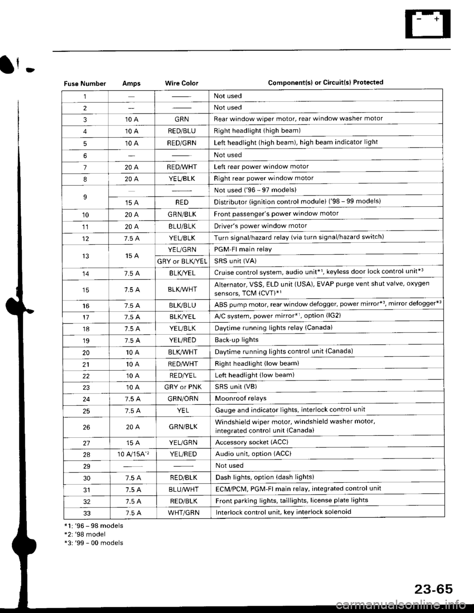
Fuse NumberAmpswire ColorComponent{sl or Circuit(sl Protected
*1r '96 - 98 models*2r '98 model*3: '99 - 00 models
,lNot used
2Not used
310 AGRNRear window wioer motor, rear window washer motor
410 ARED/BLURight headlighr thigh beam)
510 ARED/GRNLeft headlight (high beam), high beam indicator light
6Not used
7204R E D/VVHTLeft rear power window motor
820A.YEUBLKRight rear power window motor
9Not used ('96 - 97 models)
't5 AREDDistributor (ignition control module) ('98 - 99 models)
10204G RN/BLKFront passenger's power window motor
1120ABLU/BLKDriver's power window motor
127.5 AYEUBLKTurn signal/hazard relay (via turn signal/hazard switch)
t515 AYEL/GRNPGM-Fl main relay
GRY or BLK,^/ELSRS u nit (VA)
141.54B LK/YE LCruise control system, audio unit*1, keyless door lock control unit*3
BLK/lr'r'HTAlternator, VSS, ELD unit (USA), EVAP purge vent shut valve, oxygen
sensors, TCM (CVT)*'
t6BLI(,/BLUABS pump motor, rear window defogger. power mirror*3, mirror delogger*3
177.5 ABLK,/YE LA,/C system, power mirror*r. option (lG2)
18YEUBTKDaytime running lights relay (Canada)
197.5 AYEUREDBack'up lights
2010ABLK/VVHTDaytime running lights control unit (Canada)
2110 AREDA/VHTRight headlight (low beam)
2210 ARE DI/E LLeft headlight (low beam)
10 AGRY or PNKSRS UNit (VB)
247.5 AGRN/ORNMoonroof relays
257.5 AYELGauge and indicator lights. interlock control unit
204GRN/BLKWindshield wiper motor, windshield washer motor,
integrated control unit {Canada)
15 AYEL/GRNAccessory socket (ACC)
2a10 A,/'�]5A''YE L/R EDAudio unit, option (ACC)
29Not used
307.5 AR ED/BLKDash lights, option (dash lights)
1.5 ABLUA/VHTECM/PCl\4, PGM-Fl majn relay, integrated control unit
RED/BLKFront parking lights, taillights, license plate lights
337.5 AWHT/GRNlnterlock control unit. key interlock solenoid
23-65
Page 1544 of 2189
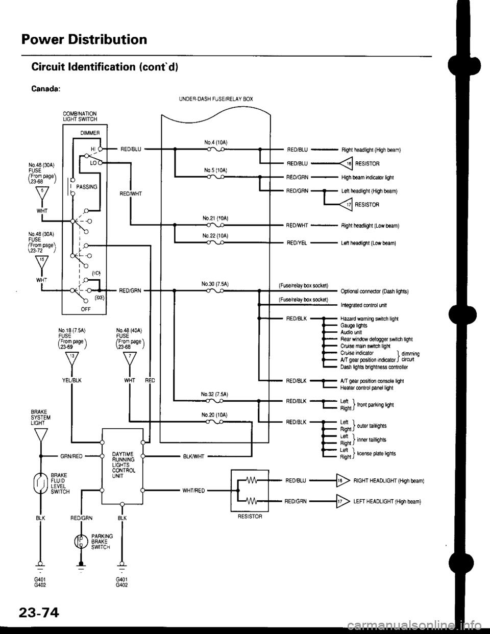
Power Distribution
Circuit ldentification (cont'd)
Canada:
COMBINATIONLIGHT SWITCH
N0.48 {30A)
RED/BLU - Right headlighl (High boam)
FEDiBLU ----< REstsTOR
REo/GRN - HiJh beam indicator lighl
BEo/GRN - Left headlighl iH,gh beam)
L
FEo/YEL - L€ll headlight (Low beam)
(Fuse/lelay box sockel)Optional conneclor (oash lighs)
Inleg6led conlrcl unil
- Hazard wanirE swilch lighl
i- Gauge lEhts
l- Audio unil
l- Re& Yrindow delogg8r swili
t- Ctuise main swrdr ligh
l- C/uise indEator l
E g"ffiry:'l,:1':::1
Refi window delog$r swildr light
Ctuise indicalor 1 dimming,T geal posilion indicator J circu(Dasn lghls brignmess co oller
BRAKESYSTEMLIGHT
V
I
l- GFf
,,4,,0*,lf tIFLUDII ,j I LEVEL
Y
SWTCH
I8LKI
I
I
I:
G401G402
REo/BLK - l/T ged position console lqhl- Hqalor codrot panel tighl
REO/BLK -F- Lefi ) .l- g;n1J lron 9arrn! qm
FEDiBLK + Letl I
F Rqn J ouer larrqns
- I Al, I
{- i'-;*; inne' raittiotts
E fifi]t'"nt"o't't'sn"
*ro,rru -$ RcHT HEADLIGHT (Hrgh beam)
BEDiGRN -+ LEFI H EADLIGHT (High beam)
I BLK
IIPARKING IEFAKE IswrrcH I
I:
G401G402
UNDER,DASH FUSE/RELAY 8OX
lo| | PASSTNGto
/Fforn page\\a-68 l
N0.48 {304)FUSE/From page\\23-72 )
N0.18 (7.54)FUSE/From page \\?3-69 J
v
YIYEUBLK
N0.48 (40A)FUSE/From paqe \\23-68 - ,/
RED6RN
23-74
Page 1598 of 2189
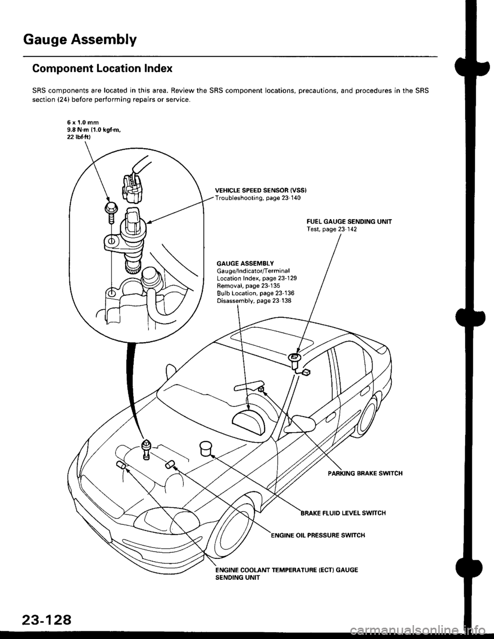
Gauge Assembly
Component Location Index
SRS components are located in this area. Review the SRS component locations, precautions, and procedures in the SRS
section (24) before performing repairs or service.
6x1.0mm9.8 N.m 11.0 kgf.m,22lbt.lrl
VEHICLE SPEED SENSOR {VSS)Troubleshooting, page 23-1 40
GAUGE ASSEMBLYGau ge/lndicator/TerminalLocation Index, page 23-129Removal, page 23-135Bulb Location, page 23-136Disassembly, page 23 138
PARKING BRAKE SWITCH
FLUIO LEVEL SW]TCH
23-128
ENGINE OIL PR€SSURE SWITCH
Page 1613 of 2189
J
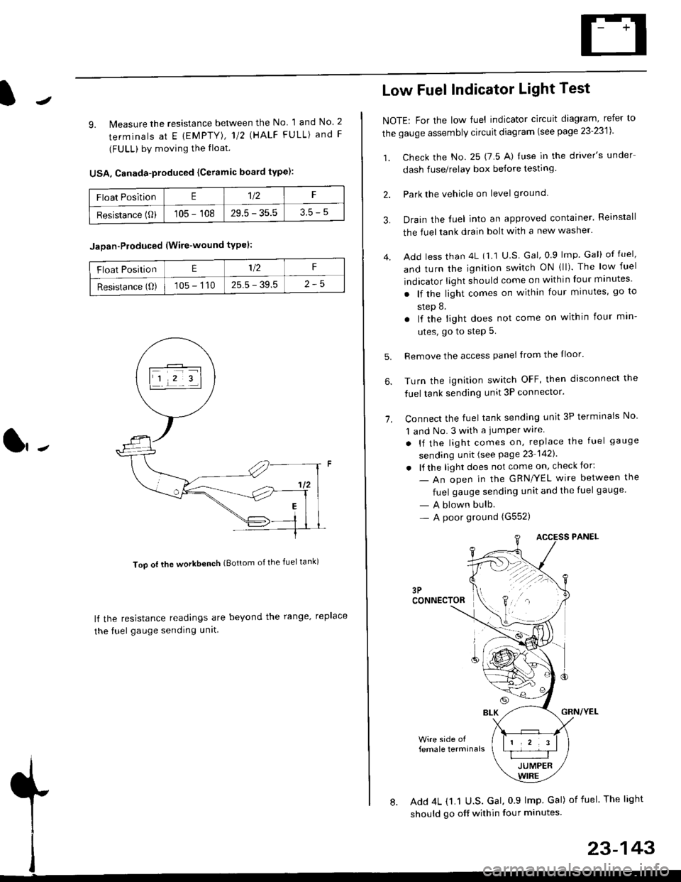
9. lMeasure the resistance between the No 1 and No. 2
terminals at E {EMPTY), 112 \HALF FULL) and F
(FULL) by moving the lloat.
USA, Canada-produced {Ceramic board type):
Too ot lhe workbench (Bottom of the fuel tank)
ll the resistance readings are beyond the range. replace
the fuel gauge sending unit
Float PositionE1t2F
Resistance (0)105 - 10829.5 - 35.53.5-5
Jaoan-Ploduced (Wire-wound typel:
Float PositionE1/2F
Resistance (O)105 - 11025.5 - 39.5
Low Fuel Indicator Light Test
NOTE: For the low fuel indicator circuit diagram, refer to
the gauge assembly circuit diagram (see page 23'2311.
1. Check the No. 25 (7 5 A) luse in the driver's under
dash fuse/relay box before testing
2. Park the vehicle on level ground.
3.
4.
Drain the luel into an approved container. Reinstall
the fueltank drain bolt with a new washer.
Add less than 4L (1 1 U.S Gal, 0.9 lmp Gal) of fuel,
and turn the ignition switch ON (ll). The low fuel
indicator light should come on within four minutes'
. lf the light comes on within four minutes, go to
step 8.
. lf the light does not come on within four min-
utes, go to step 5.
Remove the access panel lrom the Iloor'
Turn the ignition switch OFF, then disconnect the
fuel tank sending unit 3P connector.
Connect the fuel tank sending unit 3P terminals No'
1 and No. 3 with a jumPer wire
. lf the light comes on, replace the fuel gauge
sending unit (see Page 23 1421
. lf the light does not come on, check for:
- An open in the GRN/YEL wire between the
fuel gauge sending unit and the fuel gauge
- A blown bulb.- A poor ground (G552)
6.
1.
female terminals
8. Add 4L {1.1 U.S. Gal, 0 9 lmp Gal) of fuel The light
should go off within four minutes.
23-143
Page 1614 of 2189
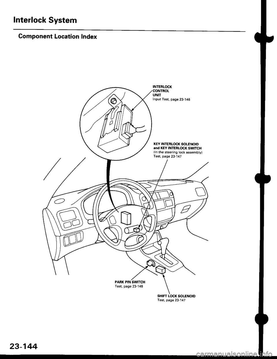
Interlock System
Component Location Index
INTERI.OCK
UNITInput Test, page 23-'146
KEY INTEBLOCK SOLENOIDrnd KEY INTERLOCK SWITCH(ln the steering lock assemblylTest, page 23-147
PARK PIN SWITCHTest, page 23-148
SHIFT LOCK SOLENOIDTest, page 23-147
23-144
Page 1616 of 2189
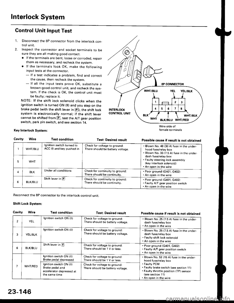
Interlock System
Control Unit Input Test
1. Disconnect the 8P connector from the interlock con-trol unit.
2. Inspect the connector and socket terminals to besure they are all making good contact.. lf the terminals are bent, loose or corroded, repairthem as necessary, and recheck the system.. lf the terminals look OK, make the followinginput tests at the connector.- lf a test indicates a problem, find and correctthe cause, then recheck the system.- lf all the input tests prove OK, substitute aknown-good control unit, and recheck the sys-tem. lf the check is OK, the control unit mustbe faulty; replace it.
NOTE: lf the shift lock solenoid clicks when theignition switch is turned ON {ll) and you step on thebrake pedal (with the shift lever in E), the shift locksystem is electronically normal; if the shift leve.cannot be shifted from E], test the Aff gear position
switch, park pin switch, and see section 14.
Key Interlock System:
CavityWireTest condition
Reconnect the 8P connector to the interlock control unit.
Shift Lock System:
Cavity WifsTest condition
INTERLOCKCONTROL UNIT
Test: Desired result
Test: Dgsired result
Wire side offemale terminals
Possible cause if result is not obtained
Possible cause if result is not obtained
WHT/BLU
lgnition switch turned toACC (lland key pushed inCheck for voltage to groundiThere should be baftery voltage.Blown No. 48 (30 A) fuse in the underhood fuse/relay boxBlown No. 33 (7.5 A) fuse in the underdash fuse/relay boxFaulty steering lock assemblylkey interlock solenoid)An open in the wire
5WHT
BLKUnder all conditionsCheck for continuity to ground:There should be continuity.
' Poor ground (G401, G402). An open in the wire
6BLK./BLUShift lever in ElCheck for continu;ty to ground:There should be continuity.Poor ground (G401, G402)Faulty Ay'T gear position switchAn open in the wire
2YELlgnition switch ON lll)Check for voltage to ground:There should be banery voltage.
. Blown No. 25 (7.5 A) fuse in the under,dash fuse/relay box. An open in the wire
3YEUBLK
lgnition swirch ON (ll)Check for voltage to ground:There should be baftery voltage.Blown No. 25 (7.5 A) fuse in the under-dash fuse/relay boxFaulty shift lock solenoidAn open in the wire
6BLI(BLUShift lever in ICheck for voltage to ground:There should be 1 V or less.Poor ground (G401, G402)Faulty A,/T gear position switchAn open in the wire
7WHT/RED
lgnition switch ON lll)Brake pedaldepressedCheck for voltage to ground:There should be 1 V or less.Blown No. 52 (15 A) Iuse in the underhood fuse/relay boxFaulty PCMFaulty brake switch (see section 1l)Faulty throttle position {TP) sensor(see section 1'l )An open in the wire
lgnition switch ON (ll)Brake pedalandaccelerator depressed atthe same time
Check for voltage to ground:There sho(Jld be battery voltage.
23-146