1996 HONDA CIVIC Engine harnes
[x] Cancel search: Engine harnesPage 1753 of 2189
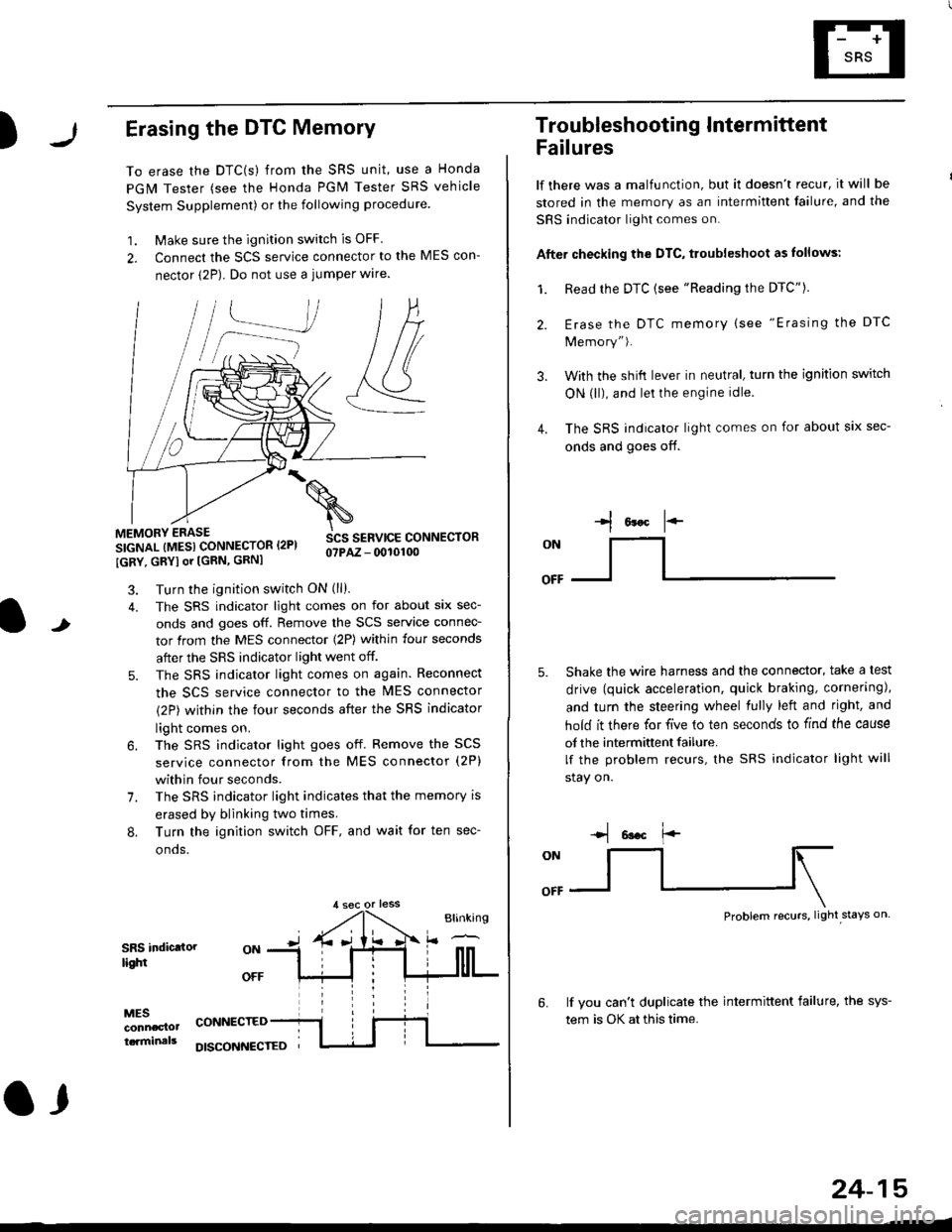
)Erasing the DTC Memory
To erase the DTC(s) from the SRS unit, use a Honda
PGM Tester (see the Honda PGM Tester SRS vehicle
System Supplement) or the following procedure
1. Make sure the ignition switch is OFF
2. Connect the SCS service connector to the MES con-
nector (2P). Do not use a jumper wlre.
]P,
&
.!--J
MEMORY ERASE
SIGNAL (MESI CONNECTOR I2PI
IGRY, GRYI or [GRN, GRNI
SCS SERVICE CONNECTORo?PAZ - 0010100
t
7.
Turn the ignition switch ON (ll).
The SRS indicator light comes on for about six sec-
onds and goes off. Remove the SCS service connec-
tor from the MES connector (2P) within four seconds
after the SRS indicator light went off.
The SRS indicator light comes on again. Reconnect
the SCS service connector to the lvlES connector
(2P) within the four seconds after the SRS indicator
light comes on.
The SRS indicator light goes off. Remove the SCS
service connector from the MES connector (2P)
within four seconds.
The SRS indicator light indicates that the memory is
erased by blinking two times.
Turn the ignition switch OFF, and wait for ten sec-
onos.
8.
SRS indictlorlighi
MESconncclottcaminals
CONNECTED
O,
DISCONI{ECTED
24-15
Troubleshooting Intermittent
Failures
lf there was a malfunction, but it doesn't recur, it will be
stored in the memory as an intermittent failure, and the
SRS indicator light comes on.
Afte. checking the DTC, troubleshoot as lollows:
1. Read rhe DTC {see "Reading the DTC"}.
Erase the DTC memory (see "Erasing the DTC
Memory").
With the shifi lever in neutral, turn the ignition switch
ON (ll), and lei the engine idle.
The SRS indicator light comes on for about six sec-
onds and goes off.
l*F
ON
tl-- -l
Shake the wire harness and the connector, take a test
drive (quick acceleration, quick braking, cornering),
and turn the steering wheel fully left and right, and
hold it there for five lo ten seconds to find the cause
of the intermittent failure.
lf the problem recurs, the SRS indicator light will
stay on.
-q 6a.c f'-
:q
Problem recurs, light stays on
3.
4.
6.lf vou can't duplicate the intermittent failure, the sys-
tem is OK at this time.
Page 1824 of 2189
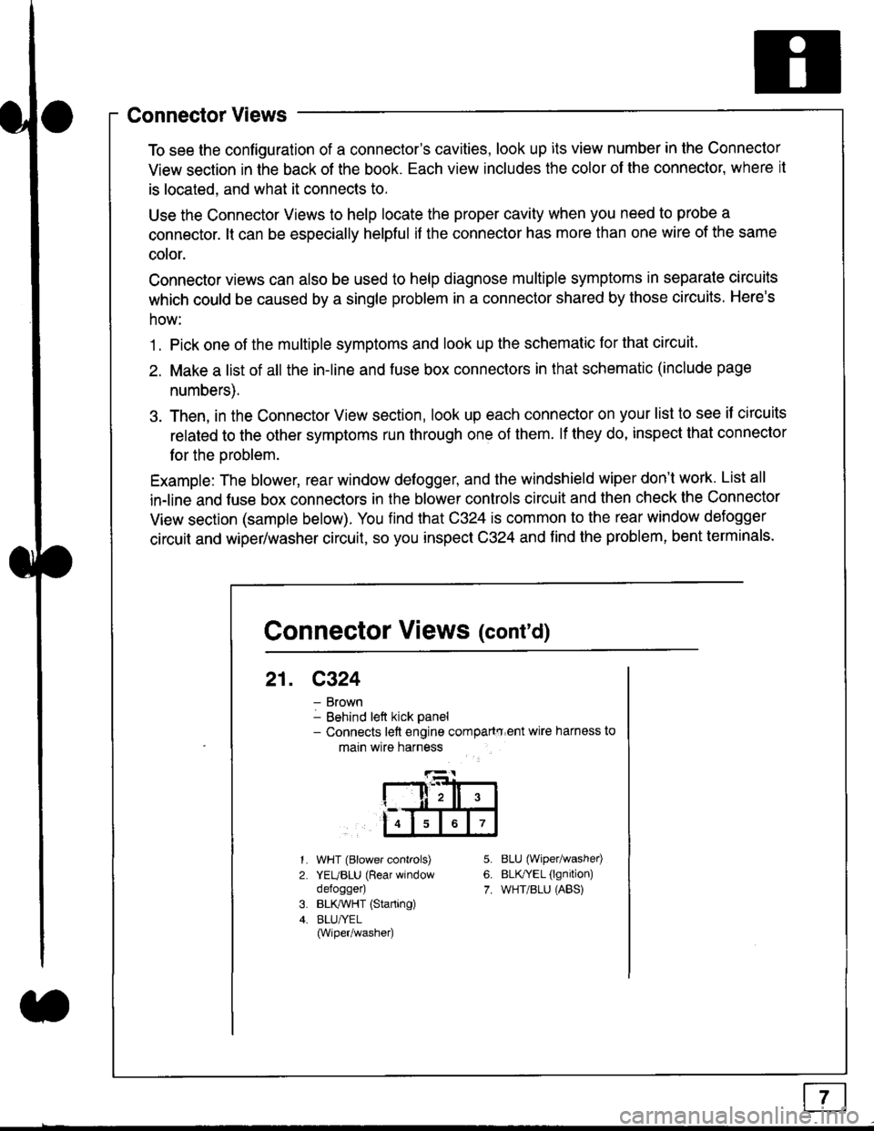
Connector Views
To see the configuration of a connector's cavities, look up its view number in the Connector
View section in the back of the book. Each view includes the color of the connector, where it
is located, and what it connects to.
Use the Connector Views to help locate the proper cavity when you need to probe a
connector. lt can be especially helpful if the connector has more than one wire of the same
cotor.
Connector views can also be used to help diagnose multiple symptoms in separate circuits
which could be caused by a single problem in a connector shared by those circuits. Here's
how:
1. Pick one of the multiple symptoms and look up the schematic for that circuit.
2. Make a list of all the in-line and fuse box connectors in that schematic (include page
numbers).
3. Then, in the Connector View section, look up each connector on your list to see il circuits
related to the other symptoms run through one of them. lf they do, inspect that connector
for the oroblem.
Example: The blower, rear window defogger, and the windshield wiper don't work. List all
in-line and fuse box connectors in the blower controls circuit and then check the Connector
View section (sample below). You find that C324 is common to the rear window defogger
circuit and wiper/washer circuit, so you inspect C324 and find the problem, bent terminals.
5.
6.
7.
1.
2.
WHT (Blower controls)
YEUBLU (Rear window
defogger)
BLK,ryVHT (Starting)
BLU/YEL(Wiper/washe0
8LU (Wiper/washed
BLfiEL (lgnition)
WHT/BLU (ABS)
Connector Views (cont'd)
21. C324
Brown
Behind left kick panel- Connects left engine compartry'ent wire harness to
main wire harness
ll,ll,
567
Page 1838 of 2189
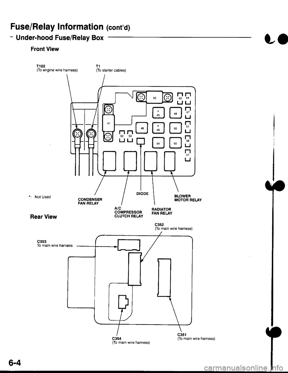
Fuse/Relay Information lcont'd)
- Under-hood Fuse/Relay Box
Front View
T'102(To engine wire harness)
LO
T1Oo starter cables)
*: Not Used
Rear View
c353To main wire harness
DE
tr
tr
tr
t-l
IJ
n
tJ
t-l51
IJ
n
IJ
n5T
IJ
[[o main wire harness)
6-4
ffo main wire harness)fto main wire harness)
Page 2109 of 2189
Connector Views (cont'd)
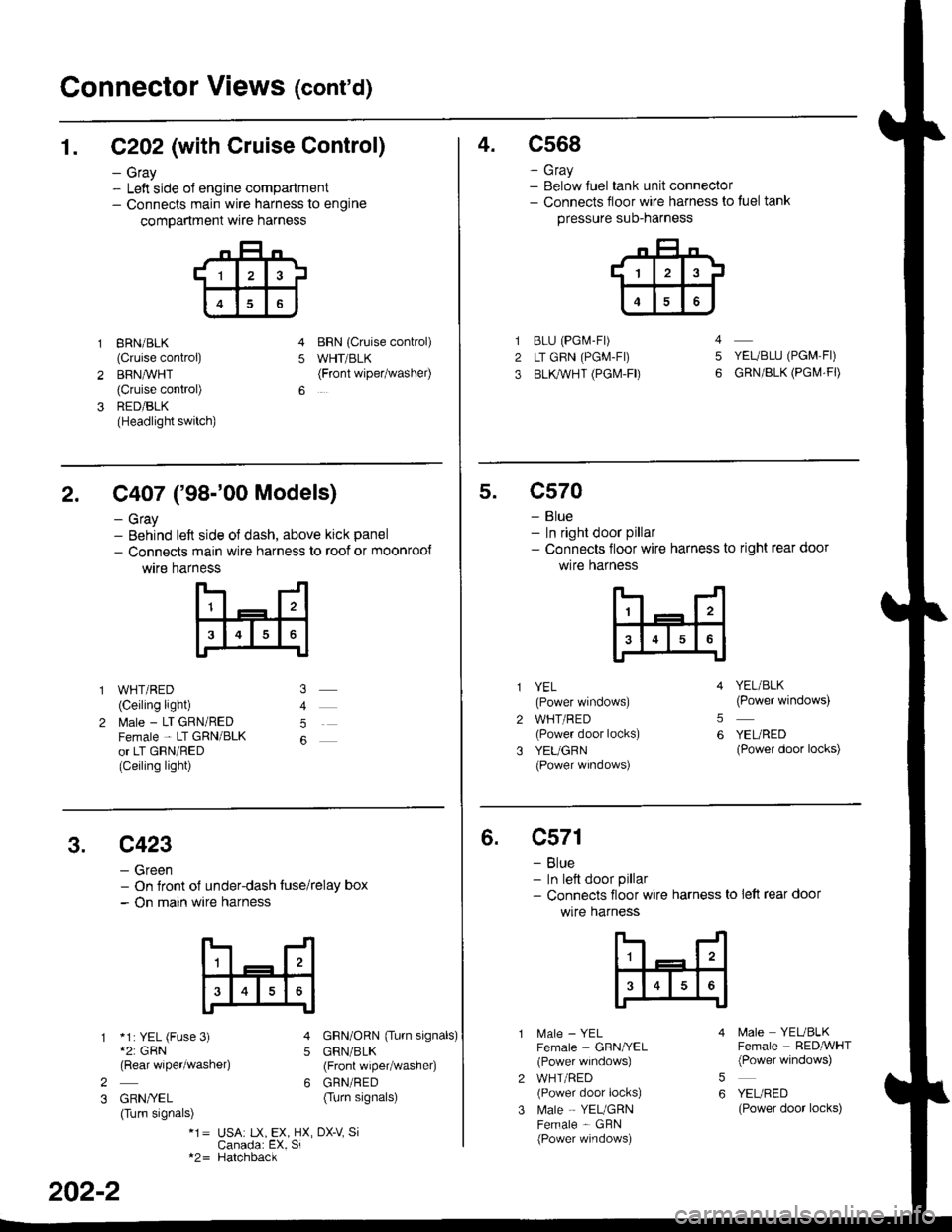
1. C202 (with Cruise Control)
- Gray- Left side ol engine compartment- Connects main wire harness to engine
compartment wre harness
gRN/BLK
(Cruise control)
BRN,ryVHT(Cruise control)
RED/BLK(Headlight switch)
BRN {Cruise conkol)
WHT/BLK(Front wipetwashel)5
4.c568
- Gray- Below Juel tank unit connector- Connects floor wire harness to tuel tank
pressure suo-narness
BLU (PGi.4-Fr)
LT GRN (PGM-FI)
BLl(WHT (PGI\4-FD
YEUBLU (PGM,FI)
GRN/BLK (PGI\,4.FD
4
5
2. C407 ('98-'00 Models)
- Gray- Behind left side ol dash, above kick panel
- Connects main wire harness to roof or moonroo{
wtre harness
WHT/RED(Ceiling light)
l\4ale - LT GRN/REDFemale - LT GRN/BLKor LT GRN/RED(Ceiling light)
5
5.c570
- Blue- In right door pillar- Connects floor wire harness to right rear door
wlre hafness
2
3
YEL(Power windows)
WHT/RED(Power door locks)
YEUGRN(Power wrndows)
YEL/BLK(Power windows)
YEURED(Power door locks)
5
6
3.c423
- Green- On Jront of under-dash tuse/relay box- On main wire harness
*1: YEL (Fuse 3)*2: GRN(Rear wiper/washe4
GRN/YEL(Turn signals)
GRN/ORN {Tu.n signals)
GRN/BLK(Front wiper/washer)
GRN/RED(Turn signals)
5
62
3
*1= USA: tX, EX, HX, DX-V SiCanada: EX, Si*2= Hatchback
202-2
6.c571
- Blue- In lett door pillar- Connects floor wire harness to lett rear door
wlre harness
MaIe _ YELFemale - GBN/YEL(Power windows)
WHT/RED(Power door locks)
Male - YEUGRNFemale - GBN(Power windows)
5
6
N4ale YEUBLKFemale - RED,ryVHT(Power windows)
YEURED(Power door locks)
Page 2110 of 2189
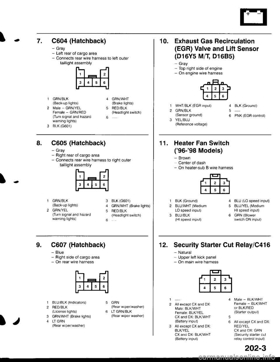
\7. C604 (Hatchback)
GRN/BLK(Back-up lights)
l\4ale GRNIYELFemale - GRN/RED(Turn signaland hazardwarning lights)
BLK (G601)
- Gray- Left rear ol cargo area- Connects rear wire harness to left outer
taillight assembly
4
5
6
1
2
GRNAVHT(Brake lights)
FED/BLK(Headllght switch)
10. Exhaust Gas Recirculation
(EGR) Valve and Lift Sensor
1
2
3
(D16Y5 MfI D1685)
- Gray- Top right side of engine- On engine wire harness
WHT/BLK (EGR input)
GRN/BLK(Sensor ground)
YEUBLU(Reference voltage)
4
5
6
BLK (Ground)
PNK (EGR control)
of cargo area
rear wire harness to right outer
assembly
n- -n
a t | _ a2a
l3I4t5tttl
IJ
I
8. C605 (Hatchback)
- Gray- Right rear- Connects
taillight
GRN/BLK(Back-up lights)
GRNTYEL(Turn signaland hazardwarning lights)
3
4
5
6
1
2
BLK (G601)
GFNAVHT (Brake lights)
RED/BLK(Headlight switch)
11. Heater Fan Switch
('96-'98 Models)
- Brown
Center of dash- On heater-sub B wire harness
BLK (Ground)
BLUAVHT (L4edium
LO speed input)
BLU/BLK(Hl speed input)
4
5
6
1
2
3
BLU (LO speed input)
BLU/YEL (Medium
Hlspeed input)
GFIN (Blowerswitch ON input)
9. C607 (Hatchback)
- Blue- Right side o{ cargo area- On rear wire harness
BLU/BLK (lndicators)
RED/BLK(License lights)
GBN,ryVHT (8rake lights)
LT GBN(Rear wiper/washe0
5
6
1
2
3
4
GRN(Rear wiper/washer)
LT GRN/BLK(Rear \/iper washer)
)/
202-3
12. Security Starter Cut Relay/C416
- Natural* Upper left kick panel- On main wire harness
1
2Allexcept CX and DXI[,4ale: BLK,^r'r'HTFemale: BLKI/ELCX and DXi BLI(WHT(Battery input)
All except CX and DX:BLK^/ELCX and DX: BLK/WHT(Baftery input)
[.4ale - BLK/WHTFemale - BLKAVHTor BLKRED(Starter output)
All excepi CX and DX:RED/YELCX and DX: GRN(Security starter c!1relay control inpul)
5
6
tl3'
Page 2112 of 2189
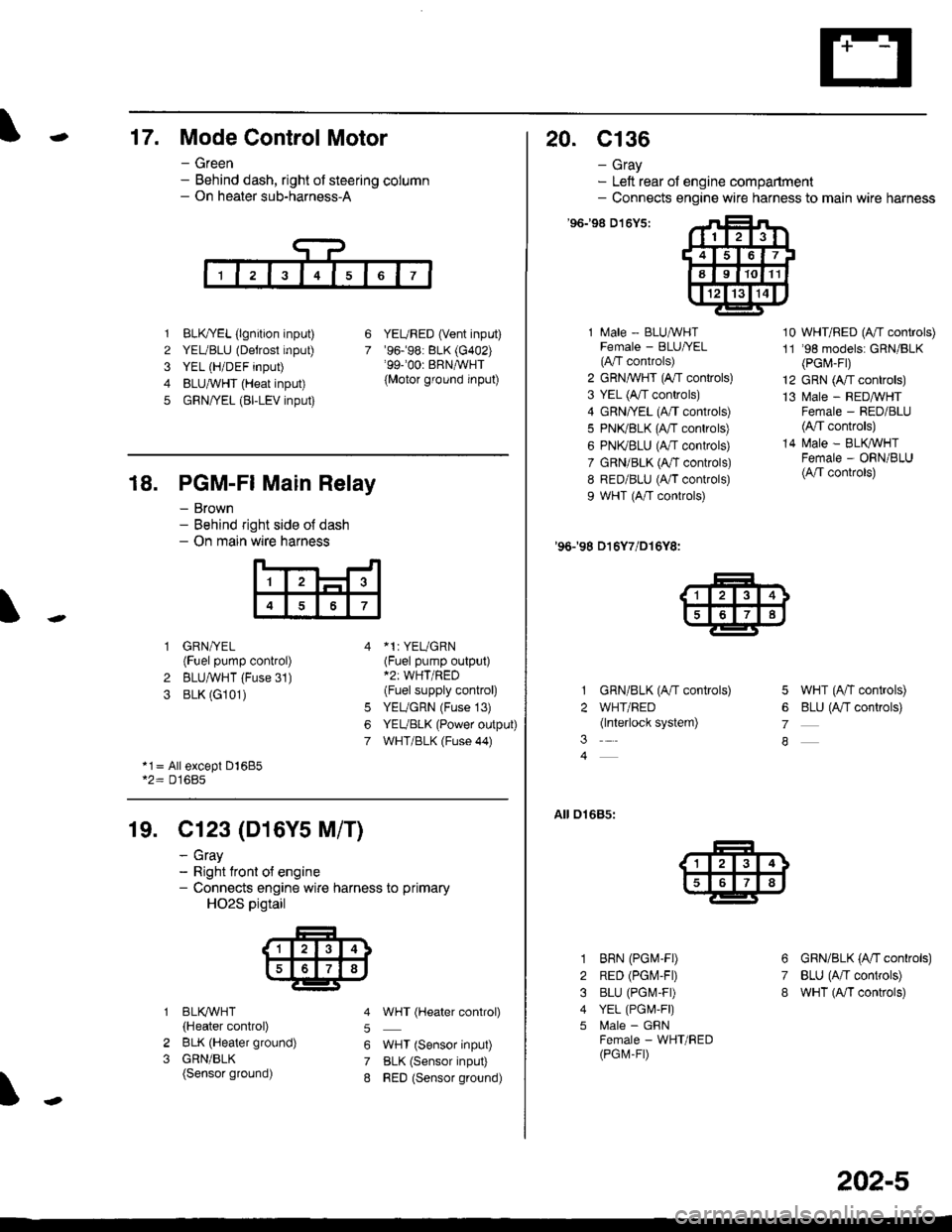
-17. Mode Control Motor
- Green- Behind dash, right of steering column- On heater sub-harness-A
1 BLK,TYEL (lgnition input)
2 YEUBLU (Detrost input)
3 YEL (H/DEF input)
4 BLUA/VHT (Heat input)
5 GRN/YEL (BI-LEV input)
YEURED (Vent input)'96.�98: BLK (G402)'99-'00r BRNAVHT
{Motor ground input)
6
7
18. PGM-FI Main Relay
- Brown- Behind right side o{ dash- On main wire harness
'l
4
1 GRN/YEL(Fuel pump control)
2 BLUAVHT (Fuse 31)
3 BLK (G101)
*1: YEUGRN(Fuel pump output)*2: WHT/RED(Fuel supply control)
YEUGRN (Fuse 13)
YEUBLK (Power output)
WHT/BLK (Fuse 44)
6
7
*1= All except Dl685*2= D16Bs
19. Cl23 (D16Y5 M/T)
2
3
BLI(WHT
{Heater control)
BLK (Heater ground)
GRN/BLK(Sensor ground)
- cray- Right tront o{ engine- Connects engine wire harness to primary
HO2S pigtail
5
6
7
8
WHT (Hgater control)
WHT (Sensor input)
BLK (Sensor input)
RED (Sensor ground)
20. c136
- Gray- Left rear of engine compartment- Connects engine wire harness to main wire harness
'96198 D't6Y5:
1 Male - BLUAVHTFemale - BLU|/EL(A"/T controls)
2 GRN,^WHT (A,/T controls)
3 YEL (A/T controls)
4 GRN/YEL (A/T controls)
5 PN(BLK (fff gs6lrq;s;
6 PNI(BLU (A/T controls)
7 GRN/BLK (Ar/T controls)
8 RED/BLU (A/T controls)
9 WHT (A/T controls)
'96198 D16Y7/D16Y8:
GRN/BLK (A/T controls)
WHT/RED(lnterlock system)
10 WHT/RED (A"/T controls)
11 '98 models: GRN/BLK(PGr,4-Fr)
12 GRN (A/T controls)
13 l\4ale - REDMHTFemale - RED/BLU(4,/T controls)
14 N4ale - BLIVWHTFemale - ORN/BLU(A/T controls)
5 WHT (A/T controls)
6 BLU (Antf se11re;s;
7
A
01685:
3
1
2
3
4
5
6
7
8
BRN (PGM-FD
RED (PGIV-FD
BLU (PGI\4-FD
YEL (PGI,4,F|)
l\4ale - GFNFemale - WHT/RED(PGM-FD
GRN/BLK (A'tl gs6trels;
BLU (A/T controls)
wHT (A/I controls)
202-5
Page 2113 of 2189
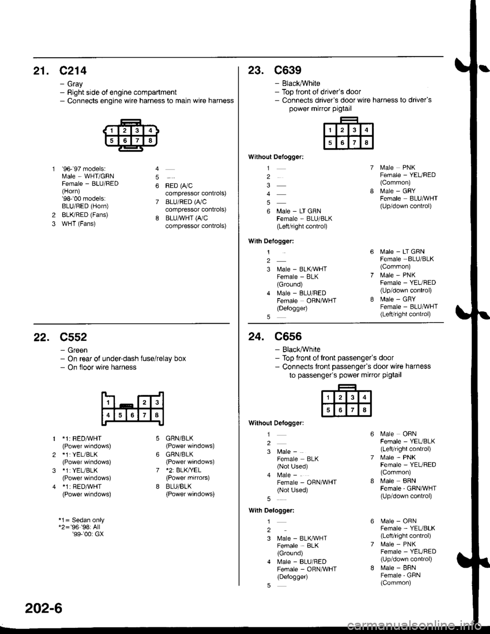
21. C214
- Gray- Right side of engine compartment- Connects engine wire harness to main wire harness
'96- 97 models:Male - WHT/GRNFemale - BLU/FED(Horn)'98-'00 models:BLU/RED (Horn)
BLKRED (Fans)
WHT (Fans)
4
5
6
7
*io t0,,"compressor controls)
BLU/RED (A,/C
compressor controls)
BLU,ryVHT (I'/C
compressor controls)
2
3
23. C639
- Black,ryVhite- Top front ot driver's door- Connects driver's door wire harness to driver's
power mirror pigtail
Without Defogger:
1
2
4
6 Male - LT GRNFema|e - BLU/BLK(Left/right control)
With Oelogger:
1
2
3 l\,lale - BLKAVHTFemale - BLK(Ground)
4 lvlale - BLU/REDFemale ORNAVHT(Delogge4
lvlale PNKFemale - YEURED(Common)
MaIe _ GRYFemale BLUA/VHT(Up/down control)
lvlale - LT GRNFemale BLU/BLK(Corrmon)
i.4ale - PNKFemale - YEURED(Up/down conkol)
Male - GRYFemale - BLU,ryVHT(Lett/right control)
22. C552
- Green- On rear of under-dash fuse/relay box- On tloor wire harness
1 *1: FEDA/VHT(Power windows)
2 *1: YEL/BLK(Power windows)
3 *1:YEL/BLK
(Power windows)
4 *1 | RED/WHT(Power windows)
*1= Sedan only*2='96''98:All'99-'00r GX
6
7
GRN/BLK(Power windows)
GRN/BLK(Power windows)*2: BLK/YEL(Power mifiors)
BLU/BLK
{Power windows)
202-6
24. C556
- Black,ryVhite- Top front of front passenger's door- Connects tront passengefs door wire harness
to passenger's power mirror pigtail
Without Defogger:
l
2
3 l\4ale -
Female BLK(Not Used)
4 l\4ale -
Female - ORN/WHT(Not Used)
With Delogger:
1
2
3 Male - BLK^VHTFemale - BLK(Ground)
4 l\.4ale - BLU/REDFemale - ORNAVHT(Defogger)
Male OBNFemale - YEUBLK(LefVright control)
l\4ale - PNKFemale - YEL/RED(Common)
Male BRNFemale - GRNA/VHT(Up/down conkol)
[.4ale - ORNFemale - YEL/BLK(Left/right control)
lrale - PNKFemale - YEURED(Up/down conkol)
l\,lale - BFNFemale'GFiN(Common)
Page 2114 of 2189
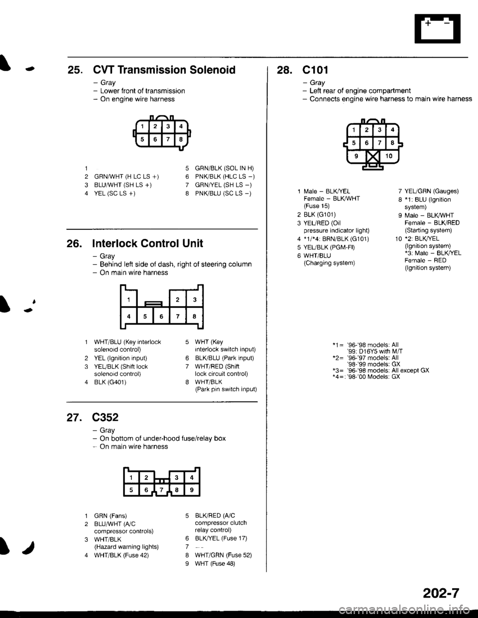
-25. CW Transmission Solenoid
- Gray- Lower front of transmission- On engine wire harness
1
2 GRNAVHT (H LC LS +)
3 BLUAVHT (SH LS +)
4 YEL (SC LS +)
5
6
7
8
GRN/BLK (SOL IN H)
PNK/BLK (HLC LS _)
GRN|VEL (SH LS -)
PNK/BLU (SC LS _)
26. Interlock Control Unit
- Gray- Behind left side oJ dash, right of steering column- On main wire harness
1
7
2
3
4
WHT/BLU (Key interlocksolenoid control)
YEL (lgnition input)
YEUBLK (Shift locksolenoid control)
BLK (G401)
WHT (Key
interlock switch input)
BLKBLU (Park lnput)
WHT/RED (Shinlock circuit control)
WHI/BLK(Park pln switch input)
6
7
27. C352
- Gray- On bottom of under-hood {use/relay box- On main wire harness
1
789
I
1
2
3
4
GRN (Fans)
BLUAVHT (fuC
compressor controlS)
WHT/BLK(Hazard warning lights)
WHT/BLK (Fuse 42)
BLKRED (A/Ccompressor clutchrelay control)
BLK,/YEL (Fuse 17)
WHT/GRN (Fuse 52)
WHT (Fuse 48)
6
7
8
I
28. C101
- Gtay- Left rear of engine compartment- Connecls engine wire harness to main wire harness
1 l\,4ale - BLK/YELFemale - BLK,ryVHT(Fuse 15)
2 BLK (G101)
3 YEURED (Oilpressure indicator light)
4 *1/*4: BRN/BLK (G101)
5 YEUBLK (PGI\4,FD
6 WHT/BLU(Charging system)
7 YEL/GRN (Gauges)
I *1: BLU (lgnition
sYstem)
9 Male - BLK VHTFemale - BLKRED(Slarting system)
10 *2: BLKryEL(lgnition system)*3: Male - BLK/YELFemale - RED(lgnition system)
*1= 96-'98 models: All'99: D16Y5 with M,iT*2= '96-'97 models: All'98-'99 modelsr GX*3= '96-'98 models: All except GX*4=: '98''00 Models: GX
202-7