Page 1531 of 2189
rt
SRS Main Harness
Conneclor or
Terminal
Number of
CavitiesLocationConnects toNotes
c801
c802
c803
c804
c805
c806
c807
2?
2
2
2
18
Under left side of dash
Above under-dash fuse/relaY
DOX
Right side of under-dash fuse/
relay Dox
Under left side of dash
Under right side of dash
Middle of floor
Middle of floor
Under-dash fuse/relay box (C911)
N4ain wire harness (C412)
Memory erase signal {MES) connector
Cable reel
Passenger's airbag assemblY
Dummy resastor connector
SRS unit
USA
Canada
G801Middle of floorBody ground, via SRS main harness
SRS MAIN HARNESS
23-61
Page 1533 of 2189
(l'-
Fuse NumberAmpswire ColorComponent(s) or Circuitlsl Protect€d
4180APower distribution
4240AWHT/BLKTo ignition switch (BAT)
437.5 AWHT/REDCeiling light, data link connector, trunk light
4415 AWHT/BLKPGM-Fl main relay
Not used
4640AWHT/BLUPower window motors (via power window relay)
477.5 AWHT/BLUAudio unit, clock, TCM (CVT), ECM/PCM (VBU)
4830AWHTNo.33 (7.5 A) fuse, To combination light switch (headlight)
49Not used
5030AWHT/GRNRear window defogger (via rear window defogger relay)
cl20AWHT/GRNPower door lock control unit, moonroof motor
15 AWHT/GRNHorn system, brake lights, brake signal
10 AWHT/BLKHazard warning light, turn signal/hazard rclay
54404WHT/REDOption {+B)
5540ABLU,A/VHTBlower motor (via blower motor relay)
204WHTCondenser fan motor (via condenser fan relay)
REDl'lc compressor clutch (via IVC compressor clutch relay)
204BLVBEDRadiator fan motor (via radiator fan relay)
23-6
Page 1552 of 2189
Ground Distribution
Circuit ldentification (cont'dl
'99-00 models:(Wilholl ABS)
r'1BL( -< 6 | c40. tFror oaoe 23-BC. II
L
E
UNDEF.H@DFUSF]RELAY BOX
_::I
A,/I gefi posilion swilchELD unil
Servi@ check connector
BL-_14BL- rl--{ry--Browe,mororreray
L4 ,r^ -.;--a-r,* -11-51 BLK - Hearer conrror o6nt n"*-fi-+aLx-lfuBLK- Hearer conrror panel
eLx -iff BLK - ff;?,m",:[:' "n'
or*
ABS glmp motor
_trl
G501
Pos€r door lock cortaol unitDivers door lock aclualorDriver's door lock switchLefl miror delogger
BLK --.+t _
F J Power wndos man swdch
-. Dive/s Fo*gr window motor
TBLK -.1 F--{ BLK - Fighr.niror detogger
tr
tr
E : Healer sub-haness A
El : Healer sub'harress B
: Floor wire hamess
: Drve/sdoorwife haness
-
|,-"*T-"^tl I
vl-L"."
G551
ort,
El ' Main *it" hanes
E : Dashboafd wirc harness
23-82
@ Passenger's doof w're hamess
Page 1555 of 2189

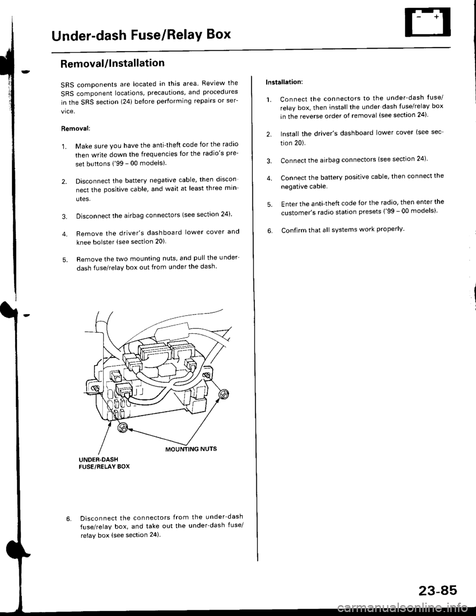
Under-dash Fuse/RelaY Box
Removal/lnstallation
SRS components are located in this area. Review lhe
SRS component locations, precautions, and procedures
in the SRS section (24) before performing repairs or ser-
vice.
Removal:
1. Make sure you have the anti-lheft code for the radio
then write down the frequencies lor the radio's pre-
set buttons ('99 - 00 modelsl.
2. Disconnect the battery negative cable. then discon
nect the positive cable, and wait at least three min
utes,
3. Disconnect the airbag connectors (see section 24)'
4. Remove the driver's dashboard lower cover and
knee bolster (see section 20)
5. Remove the two mounting nuts, and pull the under
dash fuse/relay box out from under the dash'
6. Disconnect the connectors from the under-dash
fuse/relay box, and take out the under-dash fuse/
relay box (see section 24).
lnstallation:
1. Connect the connectors to the under-dash tuse/
relay box, then install the under dash fuse/relay box
in the reverse order of removal (see section 24)'
2. Install the driver's dashboard lower cover (see sec
tion 20).
3. Connect the airbag connectors {see section 24)
4. Connect the battery positive cable, then connect the
negative cable.
5. Enter the anti-theft code lor the radio, then enter the
customer's radio station presets ('99 - 00 models)'
6. Confirm that all sYstems work properly'
23-45
Page 1559 of 2189

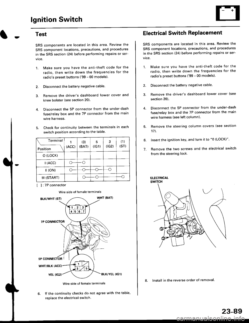
lgnition Switch
4.
Test
SRS components are located in this area Review the
SRS component locations. precautions. and procedures
in the SRS section {24} before performing repairs or ser-
1. i/ake sure you have the anti-theft code for the
radio, then write down the frequencies for the
radio's preset buttons ('99 - 00 models).
2. Disconnect the battery negative cable.
3. Remove the driver's dashboard lower cover and
knee bolster (see section 20).
Disconnect the 5P connector from the under dash
fuse/relay box and the 7P connector from the main
wire harness.
Check for continuity between the terminals in each
switch position according to the table.
I I :7P connector
Wire side ot female terminals
BLK/WHT {STIWHT IBAT}
7P CONNECTOR
WHT/BLK
YEL (IG2}BLK/YEL {IG1)
Wire side of female terminals
6. lf the continuity checks do not agree with the table,
replace the electrical switch.
Terminal
Position
1
(ACC)
(3)
(BAT)
5
{tG1) G2)
(1)
(sr)
o (LocK)
| (ACC)o--o
l (oN)o-o
III (START)o--o
1.
Electrical Switch RePlacement
SRS components are located in this area. Review the
SRS component locations, precautions, and procedures
in the SRS section \24) belore performing repairs or ser-
vtce.
1. Make sure you have the anti-theft code for the
radio, then write down the frequencies for the
radio's preset buttons {'99 - 00 modelsl.
2. Disconnect the battery negatlve cable.
3. Remove the driver's dashboard lower cover {see
section 20).
Disconnect the 5P connector from the under-dash
fuse/relay box and the 7P connector from the main
wire harness (see left column).
Remove the steering column covers {see section
11t.
lnsert the ignition key, and turn it to "0 {LOCK)".
Remove the two screws and the electrical switch
from the steering lock.
ELECTRICALswtTcH
8. Install in the reverse order of removal.
23-a9
Page 1560 of 2189

lgnition Switch
Steering Lock Replacement
SRS components are located in this area. Review theSRS component locations. precautions, and procedures
in the SRS section (24) before performing repairs or ser-vtce.
Remove:
LMake sure you have the anti-theft code for theradio, then wire down the frequencies for theradio's preset buttons ('99 - 00 models).
Disconnect the battery negative cable.
Remove the driver's dashboard lower cover andknee bolster (see section 20).
Disconnect the 5P connector from the under-dash
fuse/relay box and the 7P connector from the mainwire harness (see previous page).
Remove the steering column covers, then removethe mounting bolts and nuts from the steering col-umn (see section l7).
Lower the steering column assembly,
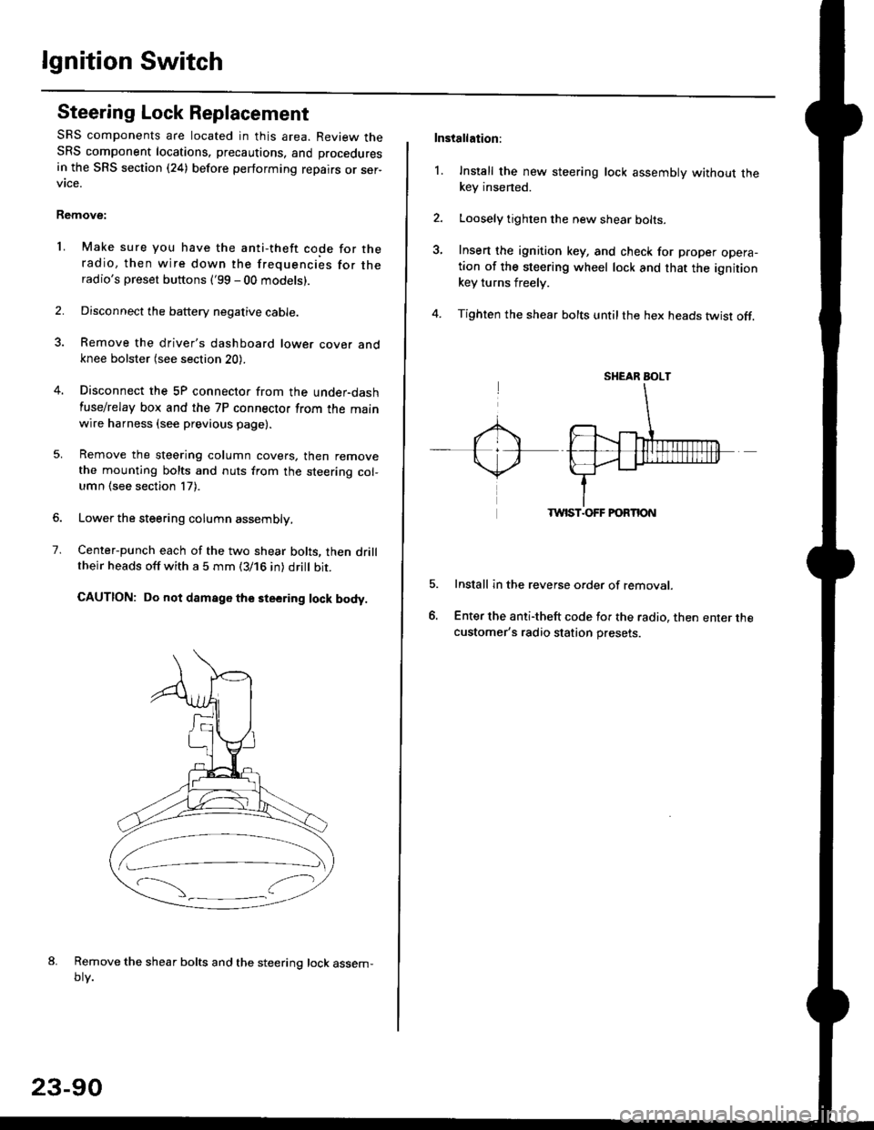
Center-punch each of the two shear bolts, then drilltheir heads off with a 5 mm (3/16 in) dritt bit.
CAUTION: Do not damago the steering lock body.
Remove the shear bolts and the steering lock assem,oty.
2.
1.
23-90
Installation:
l. Install the new steering lock assembly without thekey insened.
Loosely tighten the new shear bolts-
Insert the ignition key, and check for proper opera-tion of the steering wheel lock and that the ignitionkey turns freely.
Tighten the shear bolts untilthe hex heads twist off.
TWIST.OFF FORTION
Install in the reverse order of removar.
Enter the anti-theft code for the radio, then enter thecustomer's radio station presets.
sr{€aR SroLT
Page 1565 of 2189

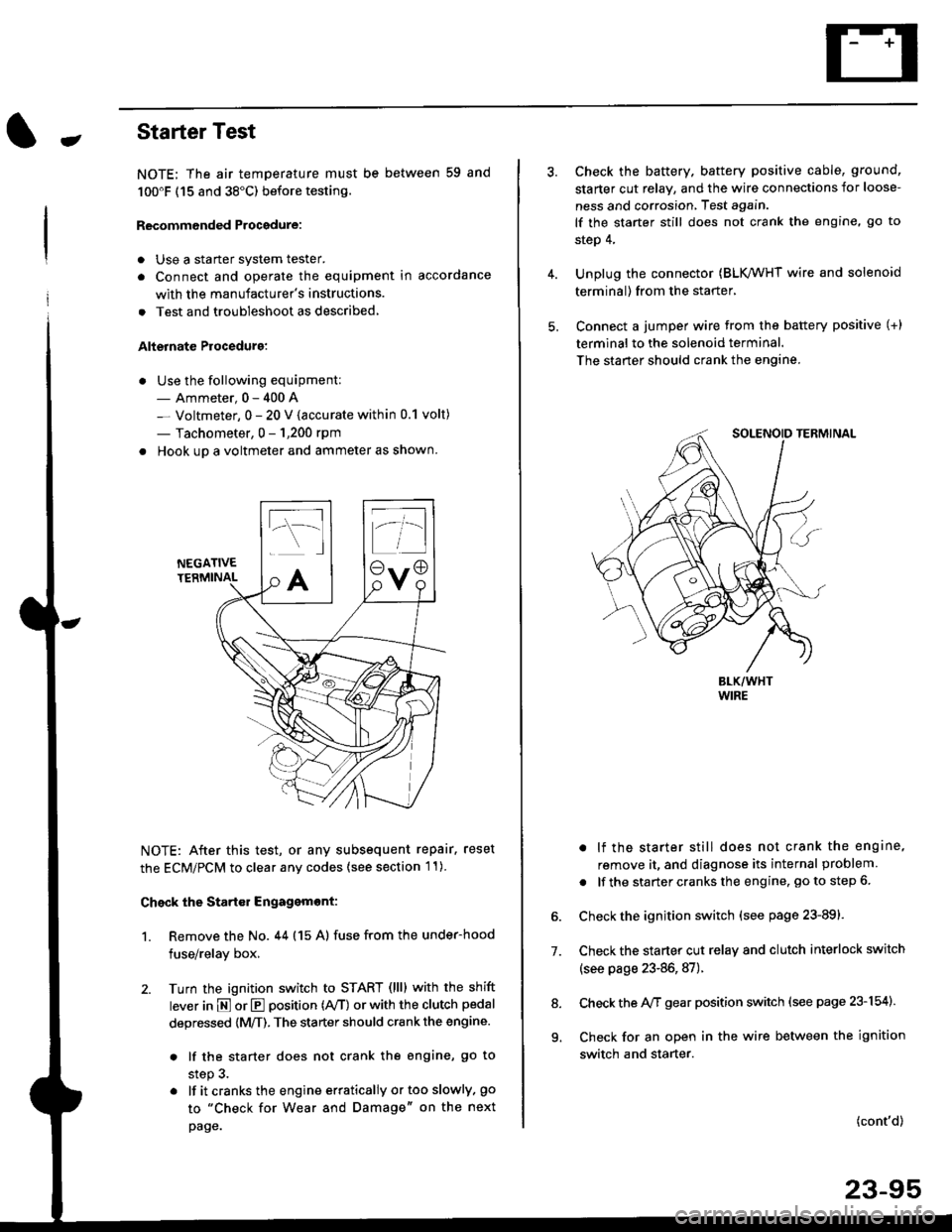
-Starter Test
NOTE; The air temoerature must be between 59 and
100'F (15 and 38"C) before testing.
Recommended Procedure:
. Use a staner system tester.
. Connect and operate the equipment in accordance
with the manufacturer's instructions.
. Test and troubleshoot as described,
Alternate Procedurg:
. Use the following equipment:- Ammeter, 0 - 400 A
- Voltmeter, 0 - 20 V (accurate within 0.1 volt)
- Tachometer, 0 - 1,200 rpm
. Hook up a voltmeter and ammeter as shown.
NEGATIVETERMINAL
NOTE: After this test, or any subsequent repair. reset
the ECM/PCM to clear any codes (see section l1)
Check the Start€r Engagemont:
1. Remove the No. 44 (15 A) fuse from the under-hood
fuse/relay box,
2. Turn the ignition switch to START (llll with the shift
lever in E or E position (rVT) or with the clutch pedal
depressed {M/T). The starter should crank the engine.
. lf the starter does not crank the engine, go to
step 3.
. lf itcranksthe engineerraticallyortooslowly, go
to "Check for Wear and Damage" on the next
page.
Check the battery. battery positive cable, ground,
starter cut relay, and the wire connections for loose-
ness and corrosion, Test again.
lf the starter still does not crank the engine, go to
step 4,
Unplug the connector (BLK,/WHT wire and solenoid
terminal) from the starter,
Connect a jumper wire from the battery positive (+)
terminal to the solenoid terminal.
The starter should crank the engine.
. lf the starter still does not crank the engine,
remove it, and diagnose its internal problem
. lf the startercranksthe engine, goto step 6.
Check the ignition switch (see page 23-891.
Check the starter cut relay and clutch interlock switch
(see page 23-86,87).
Check the A/f gear position switch (see page 23-154).
Check for an open in the wire between the ignition
switch and starter.
7.
(cont'd)
23-95
9.
Page 1572 of 2189
lgnition System
Component Location Index
IGNITION TIMING CONTROL SYSTEM
. Troubleshooting, section 11
. ldle speed Inspection/Adjustment. section 11
. Inspection and Setting, page 23-105
SERVICE CHECK CONNECTOR {2P}Iwiie colors: 8RN and BLKI
TEST TACI{OMETER CONNECTOB
IGNITION WIRESlnspection and Test, page 23-110
PLUGSInspection, page 23 1 11
Replacement, page 23'106Overhaul, page 23-107lgnition Coil Test, page 23'110lgnition Control Module llCM)Input Test, page 23-109
23-102