Page 1287 of 2189

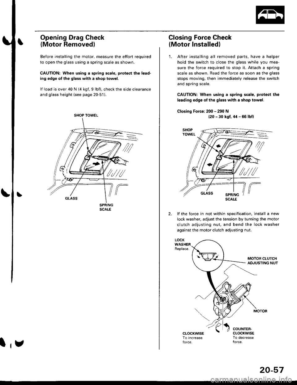
Opening Drag Check
{Motor Removed)
Before installing the motor, measure lhe effort required
to open the glass using a spring scale as shown.
CAUTION: When using a spring scale, pfotest the lead-
ing edge ol the glass with a shop towel.
lf load is over 40 N (4 kgf,9 lbf), check the side clearance
and glass height (see page 20-51).
SHOP TOWEL
l,e
20-57
Closing Force Check
(Motor Installedl
'1. After installing all removed parts, have a helper
hold the switch to close the glass while you mea-
sure the force required to stop it. Attach a spring
scale as shown. Read the force as soon as the glass
stops moving, then immediately release the switch
and spring scale.
CAUTION: When using a spring scale, protect the
lerding edge ol the glass with a shop towel.
Closing Force: 200 - 290 N(20 - 30 kst, 44 - 66 lbfl
lf the torce in not within specification, install a new
lock washer, adjust the tension by turnang the motor
clutch adjusting nut, and bend the lock washer
against the motor clutch adjusting nut.
LOCKWASHERReplace.
COUNTER.cLocKwrsETo decrease
SCALE
Page 1288 of 2189

Interior
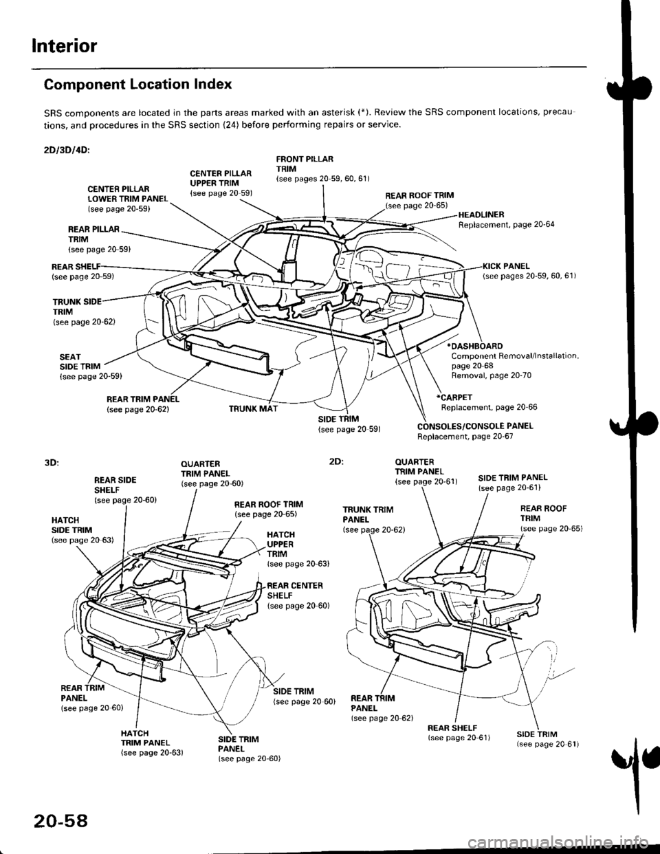
Component Location Index
SRS comDonents are located jn the parts areas marked with an asterisk (*). Review the SRS component locations, precau
tions, and procedures in the SRS section {24) before performing repairs or service.
2Dl3Dl4Dl
CENTER PILLARUPPER TRIM{see page 20 591
FRONT PILLARTRIM{see pages 20 59,60,61)
REAR PILLARTRIM
TRUNKTRIM(see page 20-62)
SEATSIDE TRIM{see page 20-59)
{see page 20 59}
CENTER PILLARLOWER TRIM PANEL(see page 20-59)
REAR ROOF TRIM(see page 20-65)
:
OUARTERTRIM PANEL
{see page 20'61)
HEADLINERReplacement, Page 20'64
*OASHBOARO
Component Removal/lnstallation,page 20 68
REARlsee page 20 59)
REAR TRIM PANEL
lsee page 20-62)
Removal, page 20-70
*CARPET
Replacement, page 20 66
PANELReplacement, page 20-67
3D:
REAR SIDESHEI-F(see page 20-60)
OUARTERTRIM PANEL(see page 20-60)SIDE TRIM PANEL(see page 20-6'l)
2Dl
HATCHSIDE TRIM(see pase 20 63)
REAR ROOF TRIM(see page 20 65)REAR ROOFTFIM(see page 20'65)HATCHUPPERTRIMlsee page 20 63)
CENTERSHELFlsee page 20 60)
REARPANELlsee page 20 60)
SIDE TRIM{see page 20 60)REARPANEL(see page 20 62)
1
HATCHTRIM PANEL(see page 20-63)
SIDE TRIMPANEL(see page 20-60)
20-54
Page 1289 of 2189
Interior Trim
tReplacement
CAUTION:
. Put on gloves to protect your hands.
o When prying with a flat-tip screwdriver, wrap it with protective tape to prevent damage.
NOTE: Take care not to bend or scratch the trim and panels.
4D:
>: Clip locationsa>,2c >,2'lo >,2E >,2
r*'" n t-lt't
\wi, i
' l ll/
_tr* @,
CENTER PILLARUPPER TRIMREAR PILLARTRIM
LOCK CYLINDER TRIM
tl'
I
E'vBELT UPPERANCHOR(see page 20-85)
Disconnect thehigh mount brakelrght connector.
T SIDE TRIMRemove the rear seat cushion and rearseat side bolster lsee page 20-19]'.
)
lnstallation is the reverse of the removal procedure.
NOTE:
. lf necessary, replace any damaged clips.. Before installing the front seat belt upper anchor
and rear shelf. make sure there are no twists or
kinks in the seat belts.(cont'd)
B>,6
REAR SHELF
k"si
fEFT KICKPANEL
20-59
Page 1290 of 2189
lnterior Trim
Replacement (cont'dl
3D:
>: Clip locationsA>,2CLIP
N;
nt-.l I'"'\R
I
")!
F >, lil
TRIM
B>,3
G >,2H>,2
t
FRONT SEATBELT UPPEBANCHORlsee page 20 86)
SIDE TRIM PANELPROTECTOR
LEFT KICKPANEL
c >,8o>,3
PIVOT BRACKET
{see page 20-80)
lnstallation is the reverse of the removal procedure
NOTE:
. lf necessary, replace any damaged clips'
. Before installing the anchor bolts, make sure there
are no tlvists or kinks in the seat belts'
E >,8
>: Screw, bolt locationsA>,3 8>,6
^l l-lEF\
#, A@ Y
*"0
c>, 1
I "4"
\s
o >,2
l@@
\---
s,4, ffi;T
FRONT PILLARB
eV
REAR SIDESHELF
SIDE TRIMPANELRemove the rear seat-back and
rear seat cushion (see Page 20_80)
Disconnect the rear speaker
connector (both sides,
for some models).
REAR TRIMPANEL
q
RIGHT KICKPANEL
"x-
20-60
Page 1291 of 2189
Il
2Di
>: Clip locationsa>,28>,3
CLIP
G>,4H >,2
D >,3>i Screw location3.4
REAR SHELF
SIOE TRIM PANELRemove the rear seat-back andrear seat cushaon (see page20-a1l.
,
Disconnect the highmount brake light
SEAT BELT
€'
/>"RIGHT KICKPANEL
)
TRIM
nJ'.'rI\ZI
1\f-
F>,8
N 4'dr
SIDE TRIM
LOWER ANCHOR(see page 20-86)
c>, 14E>,2
Installation is the reverse of the removal procedure.
NOTE:
. lf necessary, replace any damaged clips.
. Before installing the anchor bolts and rear shelf,
make sure there are no twists or kinks in the seat
belts.
FRONT PILLAR
FRONT SEATBELT UPPERANCHOR
v
.h,'t6d
\
LEFT KICKPANEL
20-61
Page 1292 of 2189
Trunk Trim
Replacement
CAUTION:
. Put on gloves to proteci your hands.
. When prying with a flat-tip screwdriver, wrap it with protestive tap€ lo prevent damage.
NOTE:
. Take care not to bend or scratch the trim and panels.
. When removing the trunk side trim or trunk trim panel, fold the seat-back forward.
Japan-produced:
4D: RIGHT TRUNKSIDE TRIM
TRUNK MAT
1B
REAR TRIMPANEL
>: Clip locationsa>,6
a:-) ,2
I g cLlP ^
l#srq-'
| ' |NNER\- crLP
B >,6
NOTE: Do not push
the inner clip in too far.
IJ
LTro
i ) :Hook locations
A i--) , r
' 2D:
TRUNK TRIM
Installation is the reverse of the removal procedure.
NOTE:
. lf necessary. replace any damaged clips.
. To install the A clips. pull the inner clip up. install
the clip, then push the inner clip until it's flush.
(
,- --
/'/ \--
/ --
20-62
Page 1293 of 2189
Hatch Trim
>:Clip locationsa>,2NOTE: Do not push thlnner clip in too far.
& ct-tp.
54d-g+-\
2. INNF
Ijy. "
\
.V ft -s---
- k-"i-t-;-a-
Replacement
CAUTION:
. Put on gloves to protect your hands.
. When prying with a flat-tip screwdrivel, wrap it with protestive tape to prevent damage.
NOTE: Take care not to bend or scratch the trim and panel.
LEFT HATCHSIDE TRIM
HATCHUPPER TRIM
Installation is the reverse of the removal procedure.
NOTE:
. lf necessary, replace any damaged clips.
. ToinstalltheAclips,pulltheinnerclipup.installtheclip,thenpushtheinnerclipuntil it'sflush
a
I
20-63
Page 1294 of 2189

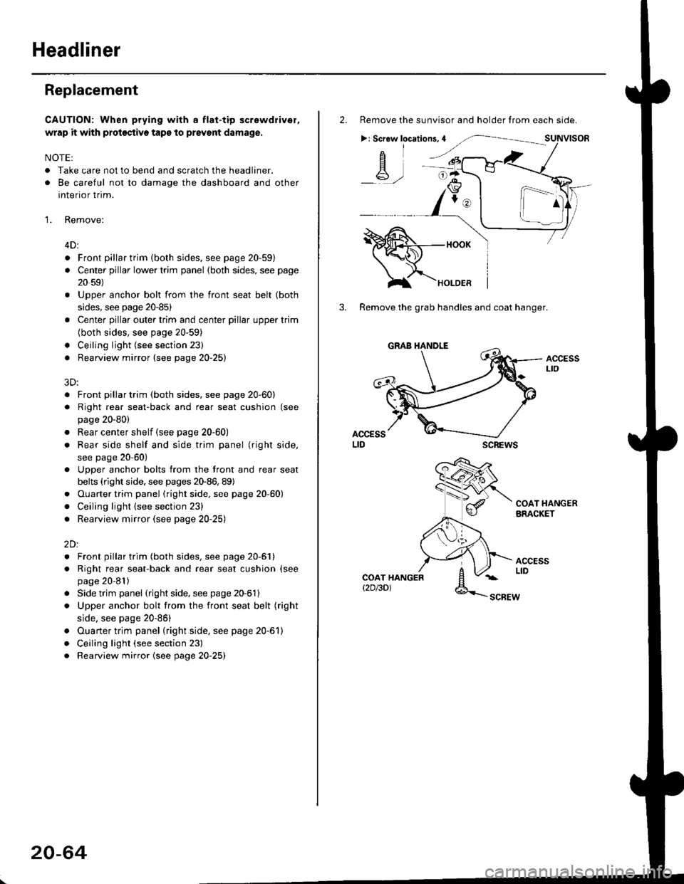
Headliner
Replacement
CAUTION: When prying with a flat-tip screwdriver,
wrap it with proioctiva tap€ to prevsnt damage.
NOTE:
. Take care not to bend and scratch the headliner.
. Be careful not to damage the dashboard and other
interior trim.
'1. Remove:
4D:
. Front pillar trim (both sides. see page 20-59)
. Center pillar lower trim panel (both sides, see page
20 59)
Upper anchor bolt from the front seat belt (both
sides, see page 20-85)
Center pillar outer trim and center pillar upper trim
(both sides, see page 20-59)
Ceiling light (see section 23)
Rearview mirror (see page 20-25)
a
a
a
a
a
3D:
. Front pillar trim (both sides, see page 20-60)
. Right rear seat-back and rear seat cushion (see
page 20-80)
. Rear center shelf (see page 20-60)
. Rear side shelf and side trim panel (right side,
see page 20-60)
. Upper anchor bolts from the front and rear seat
belts (right side. see pages 20-86, 89)
. Ouarter trim panel (right side, see page 20-60)
. Ceiling light (see section 23)
. Rearview mirror (see page 20-25)
2Dl
. Front pillar trim (both sides, see page 20-51)
. Right rear seat-back and rear seat cushion (see
page 20-81)
Side trim panel (right side, see page 20-61)
Upper anchor bolt from the front seat belt (right
side, see page 20-86)
Ouarter trim panel (right side, see page 20-6'l)
Ceiling light (see section 23)
Rearview mirror (see page 20-25)
20-64
2. Remove the sunvisor and holder from each side.
>: Screw locations,4
-A-,-
3. Remove the grab handles and coat hanger.
scREws
ACCESSLto
COAT HANGERBRACKET
ACCESSLIDCOAT HANGERt2D/3DlSCBEW
1^