Page 154 of 2189

Valves
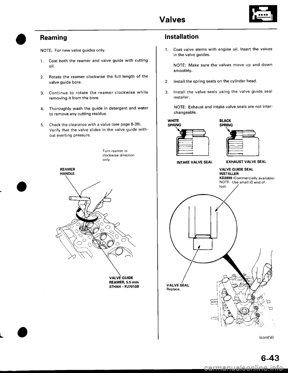
Reaming
NOTE: For new valve guides only.
1. Coat both the reamer and valve guide with cufting
orl.
2. Rotate the reamer clockwise the full length of the
valve guide bore.
3. Continue to rotate the reamer clockwise while
removing it from the bore.
4. Thoroughly wash the guide in detergent and water
to remove any cutting residue.
5. Check the clearance with a valve (see page 6-391.
Verify that the valve slides in the valve guide with-
out exerting Pressure.
Turn reamer inclockwise direclionon ly.
REAMER, 5.5 mmO7HAH. PJ'O'IOB
I
REAMER
oa)o,
o
o
1.
lnstallation
Coat valve stems with engine oil. Insert the valves
in the valve guides.
NOTE: Make sure lhe valves move up and clown
smoothly.
lnstallthe spring seats on the cylinder head.
Install the valve seals using the valve guide seal
installer.
NOTE: Exhaust and intake valve seals are not inter-
changeable.
2.
3.
WHITESPRINGBLACKSPRING
INTAKE VALVE SEALEXHAUST VALVE SEAL
VALVE GUIDE SEALINSTALLERKD2899 (Commercially available)NOTE: Use small lD end of
P
(cont'd)
6-43
Page 157 of 2189

Cylinder Head
Installation (cont'dl
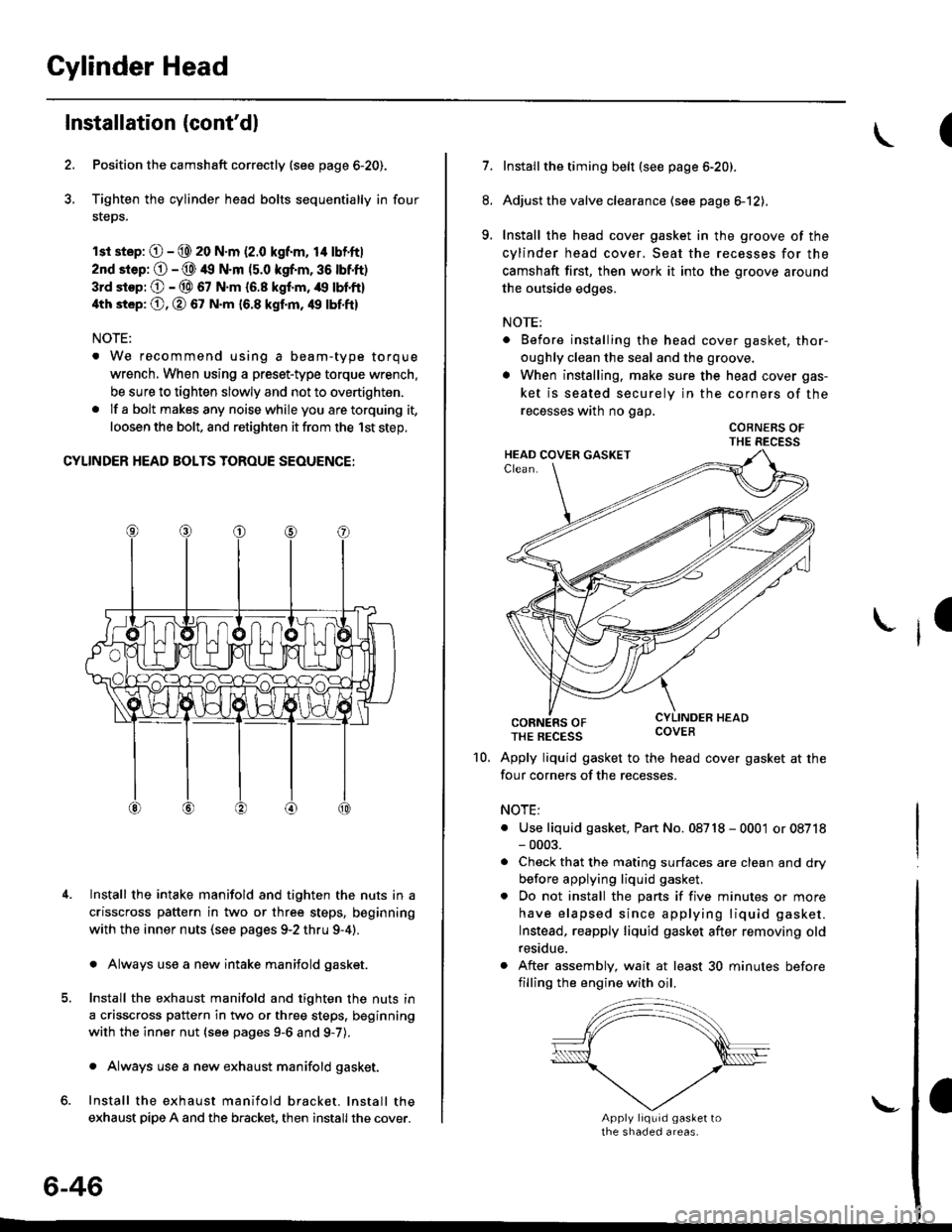
Position the camshaft correctly (see page 6-20).
Tighten the cylinder head bolts sequentially in four
steps.
rsr st.p: O - @ 20 N.m (2.0 kgf.m, 14 lbf'ft|
2nd srep: O - @ 49 N.m (5.0 kgf.m, 36 tbtft)
3rd stop; O - @ 67 N.m {6.8 kgf.m, /r9 lbl'ft}
4th st6p: O, O 67 N.m 16.8 kgf.m, 49 tbf.ftl
NOTE:
. We recommend using a beam-type torque
wrench, When using a preset-type torque wrench.
be sure to tighten slowly and not to overtighten.
. If a bolt makesany noisewhileyou aretorquing it,
loosen the bolt, and retighten it from the 1st step,
CYLINDER HEAD BOLTS TOROUE SEOUENCE:
Install the intake manifold and tighten the nuts in a
crisscross pattern in two or three steps, beginning
with the inner nuts (see pages 9-2 thru 9-4).
. Always use a new intake manifold gasket.
Install the exhaust manifold and tighten the nuts in
a crisscross pattern in two or three steps, beginning
with the inner nut {see pages 9-6 and g-7).
. Always use a new exhaust manifold gasket.
Install the exhaust manifold bracket. lnstall the
exhaust pipe A and the bracket, then install the cover.
4.
6-46
\-
(
7.Installthe timing belt (see page 6-20).
Adjust the valve clearance (see page el2),
Install the head cover gasket in the groove of the
cylinder head cover, Seat the recesses for the
camshaft first, then work it into the groove around
the outside edges.
NOTE:
. Before installing the head cover gasket, thor-
oughly clean the seal and the groove.
. When installing, make sure the head cover gas-
ket is seated securely in the corners of the
recesses wath no gap.
COBNERS OFTHE RECESS
CORNERS OFTHE REcEss covEB
Apply liquid gasket to the head cover gasket at the
four corners of the recesses.
NOTE:
. Use liquid gasket, Pan No. 08718 - 0001 or 08718- 0003.
. Check that the mating surfaces are clean and dry
before applying liquid gasket.
. Do not install the parts if five minutes or more
have elapsed since applying liquid gasket.
Instead, reapply liquid gasket after removing old
residue.
. After assembly, wait at least 30 minutes before
filling the engine with oil.
8.
9.
I
10.
Page 170 of 2189

Timing Belt
lllustrated Index
NOTE:
. Refer to page 6-59 for positioning crankshaft and pulley before installing belt.. Mark the direction of rotation on the belt before removino.a Do not use the middle cover and lower cover for storing r'emoved items.. Clean the middle cover and lower cover before installation.
WASHER
I
Replace when damagedor deteriorated.CAP NUTx 1,0 mm9.8 N.m lr.0 kgf.m, 7.2lbtftl
CYLINDERHEAD COVERRefer to page 6-86when installing.
HEAD COVER GASKETReplace when leaking,damaged or deteriorated.Apply liquid gasket atthe four corners ol therecesses,
TIMING BELTInspection, page 6-61Adjustment, page 6-61Replacement, page 6-62
I
6 x '1.0 mm9.8 N.m {1.0 kgf.m, 7.2 lbt.ftl
l0 x 1.25 mm5a N.m {5.5 kgl.m,40 tbt ftt
MIDDTE COVER
6 x 1.0 mrn9.8 N.m {1.0 kgf.m,7.2 tbt-ltl
8 x 1.25 mmN.m {5.7 kgt.m,41 tbt fr)
6x1.0mmN.m 11.0 kgf.m,7.2 tbt.ft'l
PULLEY BOLT14 x 1.25 mm177 N.m {18.0 kgf.m. 130 tbt.ft}Beplacement, page 6-59Do not use an impactwrench when installing.
TIMING BELTDRIVE PULLEY
Installwith concavesurtace facing out.Remove any oil and clean.
LOWERCOVER
CRANKSHAFT PULLEYReplacement, page 6-59
- -o
6-60
Replacement, page 6-59
Page 174 of 2189

Timing Belt
lnstallation (cont'dl
3. Install the timing belt tightly in the sequence shown.
@ Timing belt drive pulley (crankshaft) + @Adjusting pulley * @ Water pump pu ey + @ Intakecamshaft pulley + @ Exhaust camshaft pulley,
NOTE: Make sure the timing belt drive pulley andcamshaft pullevs are at TDC,
Loosen and retighten the adjusting bolt to tensionthe timing belt.
Install the lower cover and middle cover.
NOTE: Clean the middle and lower covers beforeinstalling.
Install the crankshaft pulley, then tighten the pulleybolt (see page 459).
Rotate the crankshaft pulley about five or six turnscounterclockwise so that the timing belt positions onthe pulleys.
Adjust the timing belt tension (see page A611.
7.
6-64
a
9. Check that the crankshaft pulley and camshaft pul-leys are both at TDC.
CRANKSHAFT PULLEY
CAMSHAFT PULLEY:
lf the camshaft and crankshaft pulleys are not posi-tioned at TDC, remove the timing belt, adjust theposition following the procedure on page &63, thenreinstall the timing belt.
After installation, adjust the tension of each belt.
. See section 23 for alternator belt tension adjust-ment.
. See section 22lor NC compressor belt tensionadiustment,
. See section 17 for P/S pump belt tension adjust-ment.
'l
10.
11.
I
"UP" MARKS
Page 176 of 2189
Cylinder Head
lllustrated Index (cont'dl
CYLINDER HEADBOLTS11 x 1.5 mm83 N.m {8.5 kg{.m, 61Apply engine oilto threads.
INTAKE VALVE SPRING INNER
VALVE KEEPERS
SPRING RETAINER
INTAKE VAI.VE SPRING OUTER
valvEKEEPEBS\:""j"*'
SPRING RETAINER
EXHAUST VALVESPRING
VALVE SEALReplace.
VALVE
LOST MOTIONASSEMBLY
EXHAUST VAL
VALVE SEALReplace.
SPRING SEAT
VALVE GUIDE
INTAKE VALVE
ROCKER SHAFT
SEALING AOLTS.20 mm64 N.m (6.5 kgt.m, 47 tbf.ft)
t
il
HEAO OIL CONTROLORIFICEClea n.
a
6-66
Page 178 of 2189

Cylinder Head
Removal (cont'd)
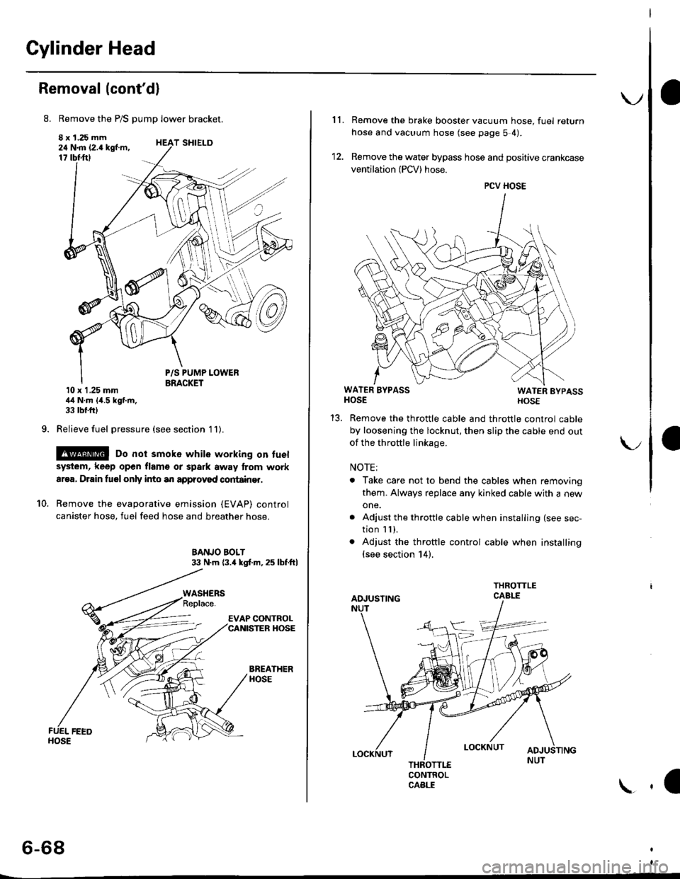
8. Remove the P/S pump lower bracket.
8 x 1.25 mm24 N.m 12.4 kgf.m,17 tbtftl
9.
T SHIELD
10.
P/S PUMP LOWERBRACKET10 x 1.25 mm44 N.m {4.5 kgf.m,33 tbf.frl
Relieve fuel pressure (see section l1).
@ Do not smok6 while working on fuel
system, keep open flam€ or spark away lrom work
ar€a, Drain fuelonly into an approved cortain€r.
Remove the evaporative emission (EVAP) control
canister hose, fuel feed hose and breather hose.
BANJO BOLT33 N.m (3.4 kgl.m.25 lbf.ftl
BREATHERHOSE
WASHERS
6-68
\.
11. Remove the brake booster vacuum hose, fuel return
hose and vacuum hose (see page 5 4).
12. Remove the water bypass hose and positive crankcase
ventilation (PCV) hose.
WATER BYPASSHOSEWATER EYPASSHOSE
Remove the throttle cable and throttle control cable
by loosening the locknut, then slip the cable end out
of the throftle linkage.
NOTE;
. Take care not to bend the cables when removing
them. Always replace any kinked cable with a new
one.
. Adjust the throttle cable when installing (see sec-
tion I I ),. Adjust the throttle control cable when installing(see section 14).
CONTROLCABLE
1a
PCV HOSE
Page 181 of 2189
Rocker Arms
Removal
'1. Hold the rocker arms together with a rubber band to
prevent them from separating.
Remove the intake and exhaust rocker shaft oil con-
trol orifices, then remove the VTEC solenoid valve
and the sealing bolts.
NOTE: The shapes ofthe intake and exhaust oil con-
trol orifices are different, ldentify the parts as they
are removed to ensure reinstallation in the original
locauons.
2.
EXHAUST ROCKERSHAFT ORIFICE
INTAKE ROCKERORIFIGEClean.Clean.
O.RINGO.RINGReplace.
RUEBER BAND
Replace. _ (lX
-dJ'v-l-
\
6-71
3. Screw 12 mm bolts into the rocker arm shafts.
Remove each rocker arm set while slowly pulling
out the intake and exhaust rocker arm shafts.
12 mm BOLTS
ROCKER ARM SHAFTS
Page 184 of 2189
Rocker Arms and Shafts
Clearance Inspection
Measure both the intake rocker shaft and exhaust rocker
shaft.
1. Measure diameter of shaft at the first rocker loca-
tron.
2. Zero gauge to shaft diameter.
Surlace shor/ld be smooth.
MICROMETER
6-74
3. Measure the inside diameter of each rocker arm and
check for out-of-round condition
Rocker Arm-to-Shaft Clearance:
Intake and Exhaust
Standard {Newl: 0.025 - 0.052 mm
{0.0010 - 0.0020 in)
Service Limit: 0.08 mm {0.003 in)
Inspect rocker armface for wear.
Repeat for all rockers.- lf over limit, replace rocker shaft and all overtol-
erance rocker arms.
NOTE: lf any rocker arm needs replacement, replace
all three rocker arms in that set {primary, mid, and
seconoary).