Page 1392 of 2189

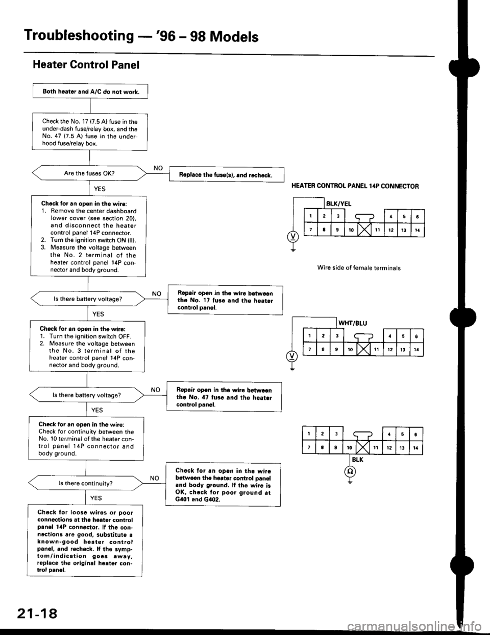
Troubleshooting -'96 - 98 Models
Both heater and A/C do not work.
Check the No. 17 {7.5 A) fuse in theunderdash fuse/relay box, and theNo. 47 (7.5 A) fuse in the underhood fuse/relay box.
R.phce the fuso{s), .nd rccheck.
Chack tor an open in the wi.e:1. Remove the center dashboardlower cover (see section 20),and disconnect the heatercontrol panel 14P connector.2. Torn the ignition switch ON {ll).3. Measure the voltage betweenthe No. 2 terminal of theheater control panel 14P con-nector and body ground.
Rcpair opGn in th€ wiro betwoonthe No. 17 tuse and the hoatclcontrol panel.
ls there baftery voltage?
Check for an opon in the wiro:1. Turn the ignition switch OFF.2. Measure the voitage betweenthe No. 3 terminal of theheater control panel 14P con-nector and body ground.
Rgprii open in th6 wira b€twacnthe No. il7 tui. and the heat.tcont.ol p.nal.
ls there battery voltage?
Check foi an open in the wi.e:Check for continuity between theNo. 10 terminal ot the heater con-trol panel 14P connector andbody ground.
Check lor an opon in tho wireb€{w6on the hoator control oaneland body ground. lI the wirc isOK, check tor poor ground atG401 .nd G4O2.
Check for looae wiaos or ooolconnections at the hoater controlpanol 14P connector. lf the con-nactions dre good. 3ubstitute tknown-9ood heater controlpanel, and rech6ck. It tho symp-tom/indication 9oe3 .wry,replace the original heatel con-trol oanol.
Heater Control Panel
HEATER CONTROL PANEL 1,lP CONNECTOR
Wire side of female terminals
21-18
Page 1393 of 2189

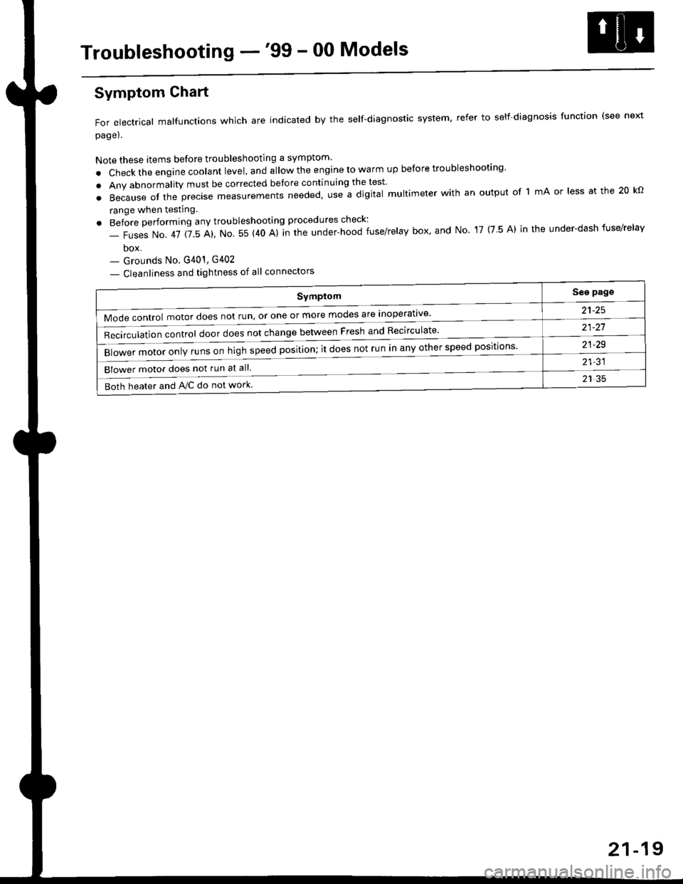
Troubleshooting -'99 - 00 Models
Symptom
Mode control motor does not run, or one or more modes are inoperat've'
Recirculation control door does not change between Fresh and Recirculate'
Blower motor only runs on high speed position; it does not run in any other speed positions
Blower motor does not run at all.
Both heater and Ay'C do not work
See pags
a1_tq
21-21
21-29
21-31
21 35
Symptom Chart
For electrical malfunctions which are indicated by the self-diagnostic system, refer to self-diagnosis function (see next
page).
Note these items before troubleshooting a symptom'
. Check the engine coolant level, and allow the engine to warm up before troubleshooting'
. Any abnormality must be corrected before continuing the test
.Becauseoftheprec|semeasurementsneeded,UseadigitaImu|timeterwithanoutputoflmAor|essatthe20ko
range when testing
. Before performing any troubleshooting procedures check:
- Fuses No. 41 115 Al, No 55 (40 A)]n the under-hood fuse/relay box' and No 17 (7 5 A) in the under-dash fuse/relav
box- Grounds No. G401, G402
- Cleanliness and tightness of all connectors
21-19
Page 1405 of 2189
Blower Motor
BLOWER MOTOR 2P CONNECTOR
Wire side of lemale terminals
JUMPERWIRE
(cont'd)
21-31
Blower motor does not run at all.
Check the No. 55 (40 A) Iuse in
the under-hood fuse/relay box,
and the No. 17 (7.5 A){use in the
undeFdash fuse/relay box.
Boplace th€ fuse(3), and rechock.
Check th€ blow€r motor Powelsupply circuit:1. Disconnect the blower motor
2P connector.2. Turn the ignition switch ON {ll).
3, Measure the voltage between
the No. 1 terminal oI the blow
er motor 2P connector and
body ground.
ls there battery voltage?
Check tha blower motor:
1. Turn the ignition switch OFF
2. Reconnect the blower motor
2P connector.3. Connect the No.2 terminal o{
the blower motor 2P connector to bodv ground with a
tumper wire.4. Turn the ignition switch ON {ll}
Does the blower motor run?
fo page 21-32
To page 21-33
Page 1406 of 2189

Troubleshooting -'99 - 00 Models
From page 21-31
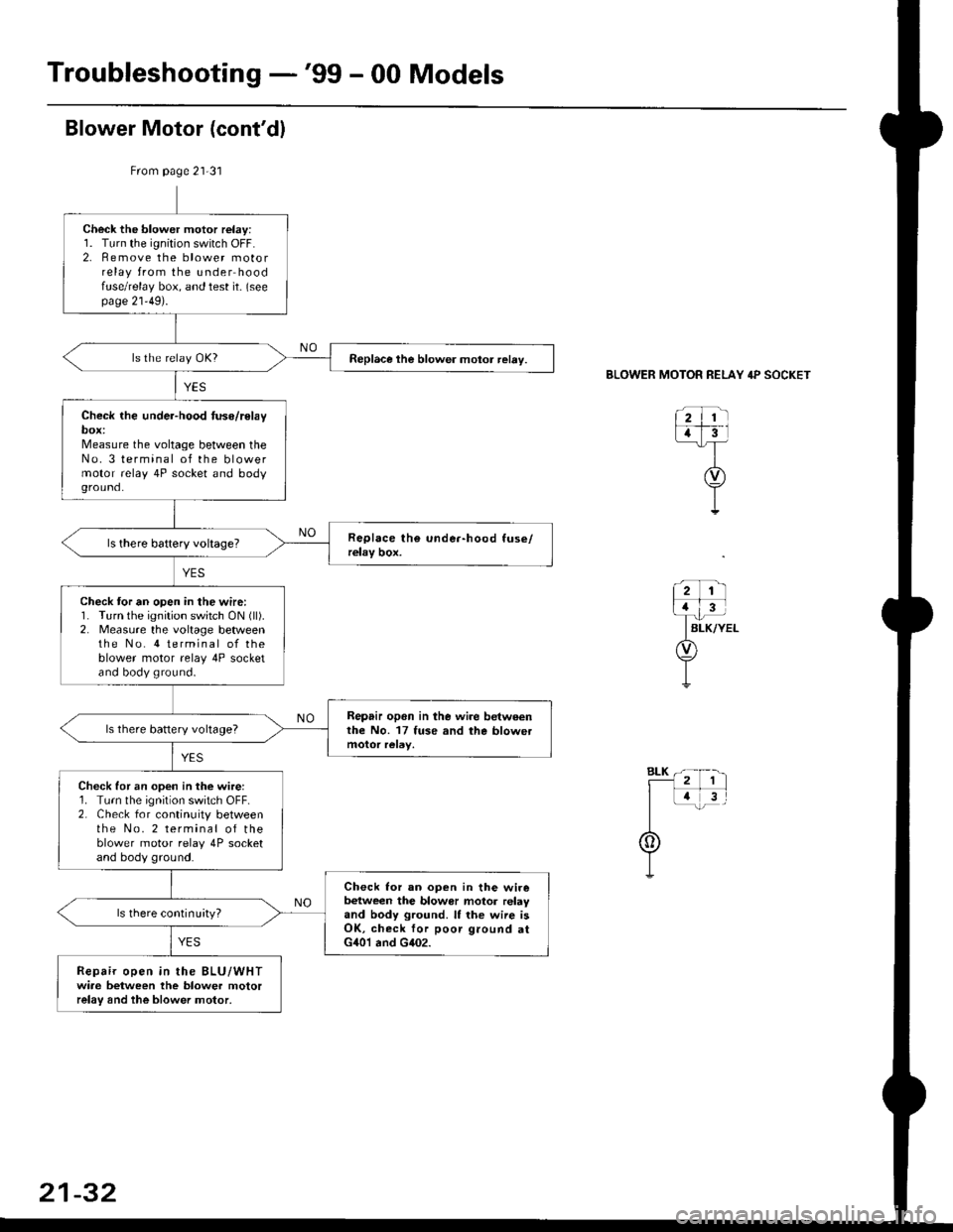
Check the blower motor relay:1. Turn the ignition switch OFF.2. Remove the blower motorrelay from the under hoodfuse/relay box, and test it- (seepage 21'49).
Replace the blower motor relay.
Check the under-hood tuse/relaybox:Measure the voltage between theNo. 3 terminal of the blowermotor relay 4P socket and bodyground.
Check tor an open in the wire:1. Turn the ignition switch ON (ll).
2. Measure the voltage betweenthe No. 4 terminal of theblower motor relay 4P socketand body ground.
Repair opon in lhe wire betweenthe No. 17 fuse and the blowetls there battery voltage?
Check for an open in the wire:1. Turn the ignition switch OFF.2. Check for continuity betweenthe No. 2 terminal of theblower motor relay 4P socketand body ground.
Check lor an ooen in the wirebetween the blowor motor relayand body ground. It the wiie isOK, check for poor ground atG401 and G402.
ls there continuityl
Repair open in the BLU/WHTwiae between the blower motorrelay and the blower motor,
BLOWER MOTOR RELAY 4P SOCKET
21-32
Page 1409 of 2189

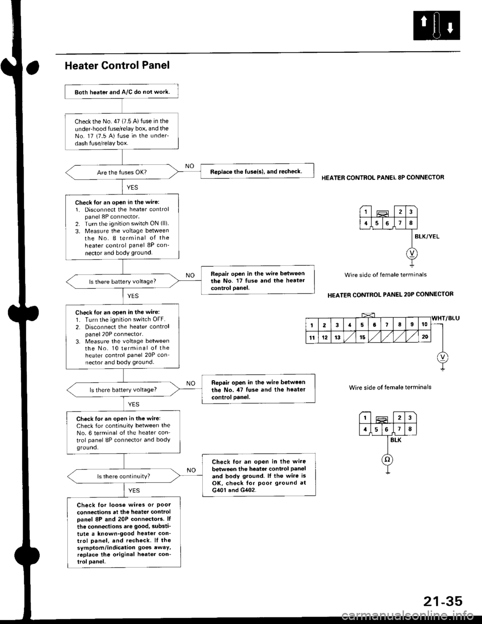
Both heater and A/C do nol work.
checkthe No.47 (7.5 A)fuse in the
under-hood fuse/relay box, and theNo. 17 {7.5 A) fuse in the under-
dash fuse/relay box.
ReDlace the tuse{s), and recheck.
Check lor an open in the wire:
1. Disconnect the heater controlpanel 8P connector,2. Turn the ignition switch ON (ll).
3. Measure the voltage between
the No. I terminal of the
heater control panel 8P con-
nector and body ground.
Repair open in the wire betweenthe No. '17 luse and th6 heatercontrol oanel,ls there battery voltage?
Check for an open in the wire:
1. Turn the ignition switch OFF.
2. Disconnect the heater controlpanel20P connector.3. Measure the voltage lletweenthe No. 10 terminal of theheater control Panel 20P con-nector and body ground.
Repair op6n in the wir€ between
the No. il7 tuse and the heater
controloanel,ls there battery voltage?
Check for an open in the wite:Check for continuity between theNo. 6 terminal of the heater con
trol panel 8P connector and bodyground.
Ch6ck tor an open in lhe wire
betwoen the heator control Paneland bodv ground. lf the wire isOK, check for poor ground atG401 and G402.
ls there continuity?
Check for looso wires or Poolconneciions at the heater controloanel 8P and 20P connectors. lf
the connections are good, substi'
tute a known-good heat€r con-trol Danel, and recheck. lI thesymptom/indication goes awaY,r6place the original h€ater con-troloanel.
HEATER CONTROL PANEL 8P CONNECTOR
BLK/YEL
Wire side of female terminals
HEATER CONTROL PANEL 2OP CONNECTOR
Wire side of temale terminals
I2
1578
BLK
o
1
4I
v
Page 1428 of 2189
Wiring/Gonnector Locations
A/C DIODE.CONDENSER FAN RELAY,COMPRESSOR CLUTCH RELAY(Located in the under,hood fuse/relay box)
COND€NSER FANCONNECTOR
COMPARTMENTWIRE HARNESS
CONNECTOR
22-4
Page 1430 of 2189
Circuit Diagram
UNDER DASHFUSE/RELAY 8OX
N0.17 (7.54)
'96 - 98 Models
UNDER.HOOD FUSEi BELAY BOX
WHT/SLU BLKYEL
BLK
+
G751
3
'o
I8LK
I
G40lG402
GNITON SWITCH
N0.41 (8rA) N0.42 (40A)
COMPBESSORCLUTCHBELAY
BLUMHT
,l
(E) i,T'
BLUi BED
A/c ITHERMOSTAI BLU/REO
CONDENSEFFAN MOTOR
*F,.X,
FAN rl
BLK
{
G401G402
HEATERswrlcH
32
22-6
Page 1431 of 2189
'99 - 00 Models
UNDER DASHFUSE/BELAY BOX
No.l7 (7.54)
BLK
I
G751
$*"
O :8P coNNEcToF
n :20P CONNECToF
E 12P coNNEcroRBLK
d-
G401G402
UNDER HOOD FUSE/RELAY 8OX
N0.41 (P,0A) N0.42 (404)
COMPRESSORCLUTCHFELAY
GNITON SWTCH
HEATER CONTROL PANEL
22-7