1996 HONDA CIVIC Remove dashboard
[x] Cancel search: Remove dashboardPage 1679 of 2189
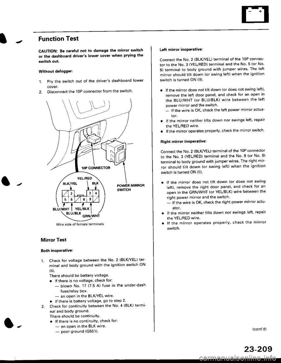
Function Test
CAUTION: Be careful not to damage the mirror switch
or the dashboard drivel's lower covel when prying the
swhch out.
Withoui defogger:
1. Pry the switch out of the driver's dashboard lower
cover.
2. Disconnect the 10P connector from the switch.
lOP CONNECTOR
BLU/WHT
YEL/RED
BLK/YELBLK
4
568
YEL/BLK
POWER MIRRORswtTcH
\:/"*jgil*-(
Wire side of female termanals
Mirror Test
Both inoperative:
1. check for voltage between the No. 2 (BLVYEL) ter
minal and body ground with the ignition switch ON
0 r).
There should be batterY voltage
. If there is no voltage, check for:
- blown No. 17 (7 5 A) fuse in the under-dash
tuse/relay box- an open in the BLK'/YEL wire.
o lf there is battery voltage, go to step 2.
2. Check for continuity between the No 4 (BLK) termi-
nal and body ground.
There should be continuity.
. lf there is no continuity, check for:
- an open in the BLK wire.
- poor ground (G551).
Left mirror inoporalive:
connect the No. 2 {BLK/YEL) terminal of the 10P connec-
tor to the No. 3 (YEURED) terminal and the No 5 (or No
6) terminal to body ground with jumper wires The left
mirror should tilt down (or swing left) when the ignition
switch is turned ON (ll)
. lf the mirror does not tilt down (or does not swing left),
remove the left door panel. and check for an open in
the BLU/WHT (or BLU/BLK) wire between the left
power mirror and the switch
- lf the wire is OK. check the left power mirror actua-
tor.
lf the mirror neither tilts down nor swings left. repair
the YEURED wire.
lf the mirror operates properly, check the mirror switch'
Right mirror inoperative:
Connect the No. 2 (BLK /EL) terminal of the 10P connector
to the No. 3 (YEURED) terminal and the No. 9 (or No 8)
terminal to body ground with jumper wires The right mir-
ror should tilt down (or swing left) when the ignition
switch is turned ON (ll).
. lf the mirror does not tilt down (or does not swlng
left), remove the right door panel. and check for an
open in the GRN/WHT (or YEUBLK) wire between the
right power mirror and the switch.
- lf the wire is OK, check the right power marror actu-
ator.
. lf the mirror neither tilts down nor swings left. repair
the YEURED wire
. lf the mirror operates properly, check the mirror
switch.
(cont'd)
23-209
Page 1681 of 2189
I
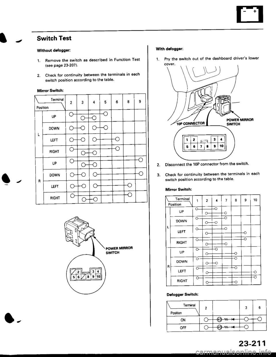
r Switch Test
Without detogg€r:
1. Remove the switch as dsscribed in Function Test
(see page 23-207).
2. Check for continuity betw€en the terminals in each
switch position according to the table.
Mirror Switch:
POWER MIRROB
swlTcH
Terminal
rL*"--_\
23456n9
L
UP-o
o-
DOWNo--oo--o
LEFTo-o--o
RIGHTo--o
o--o
UPo--o
o--o
DOWNo--oo--o
LEFIo--oo--o
RIGHT-o
o--o
l-
23-211
1. Prv the switch out of the dashboard driver's lower
With defogger:
POWER MIRRORswtTcH
Disconnect the 1OP connector from the switch'
Check for continuity between the terminals in each
switch position according to the table
Mirror Switch:
Terminal
Position \l2789't0
L
UPo-o-
-o-o
DOWNo-o--o-a
o-
o-
-o--o
RIGHTo--o
o--O
UPGo-
-o-o
DOWNo--o
G--o
LEFTo--o-oo-
RIGHT
-o
o--o
Dofogger Swhch:
Terminal
Posilion \
2
ONo-/l>\-osv
OFFo---o
Page 1687 of 2189
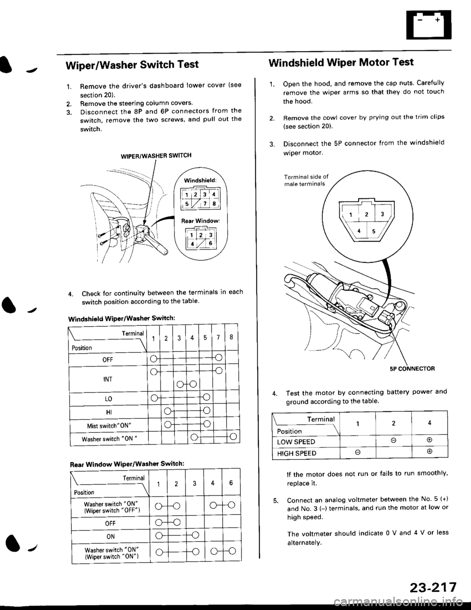
Wiper/Washer Switch Test
Remove the driver's dashboard lower cover {see
section 20).
Remove the steering column covers.
Disconnect the 8P and 6P connectors from the
switch, remove the two screws, and pull out the
switch.
4. Check tor continuity between the terminals in each
switch position according to the table
Windshield Wiper/Washer Switch:
Terminal
Position \
12357I
OFFoo
INTo-o
oo
LOoo
HIoo
l\4ist switch"0N"oo
Washer switch "0N "oo
Rear Window WiPer/Washer Switch:
I Terminal
'i"*
--J2346
Washer switch "0N"
(Wiper switch "OFF"lo--oo--o
OFFo--o
ONo--o
Washer switch "0N"
{Wiper switch "0N")o--oo--o
1.
WIPER/WASHER SWITCH
Windshield:
l1 2 314 |
li.l7a,lil
Rear Window:
11 z 3l
lT-,rtl
Windshield Wiper Motor Test
1.Open the hood, and remove the cap nuts. Carefully
remove the wiper arms so that they do not touch
the hood.
Remove the cowl cover by prying out the trim clips
(see section 20).
Disconnect the 5P connector lrom the windshield
wiper motor.
Test the motor by connecting battery power
ground according to the table.
lf the motor does not run or fails to run smoothiy,
replace it.
5. Connect an analog voltmeter between the No. 5 {+)
and No.3 {-) terminals. and run the motor at low or
high speed.
The voltmeter should indicate 0 V and 4 V or less
alternately.
Terminal
i**l*-
-_\14
LOW SPEEDo@
HIGH SPEEDo@
23-217
Page 1712 of 2189
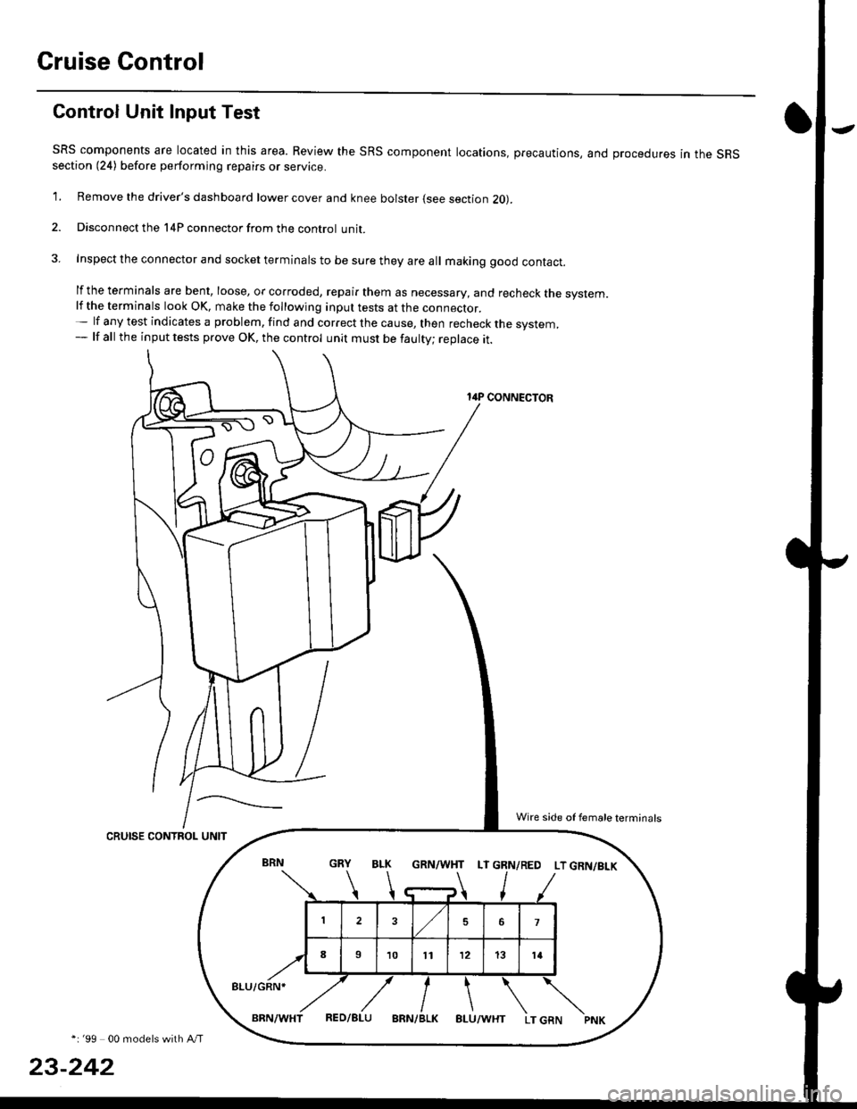
Cruise Control
Gontrol Unit Input Test
SRS components are located in this area. Review the SRS component locations, precautions, and procedures in the SRSsection (24) before performing repairs or service.
1. Remove the driver's dashboard lower cover and knee bolster (see section 20).
2. Disconnect the l4P connector from the control unit.
3. Inspect the connector and socket terminals to be sure they are all making good contact.
lf the terminals are bent, loose, or corroded, repair them as necessary, and recheck the system.lf the terminals look OK, make the following inpul tests at the connecror.- lf any test indicates a problem, find and correct the cause, then recheck the system,- lf all the input tests prove OK, the control unit must be faulty; replace it.
14P CONNECTOR
CRUISE CONTROL UNIT
*i '99 00 models with A/T
23-242
GRN/WHT LT GRN/RED LT GRN/BI-K
8LU/GRN*
Wire side of female terminals
Page 1714 of 2189
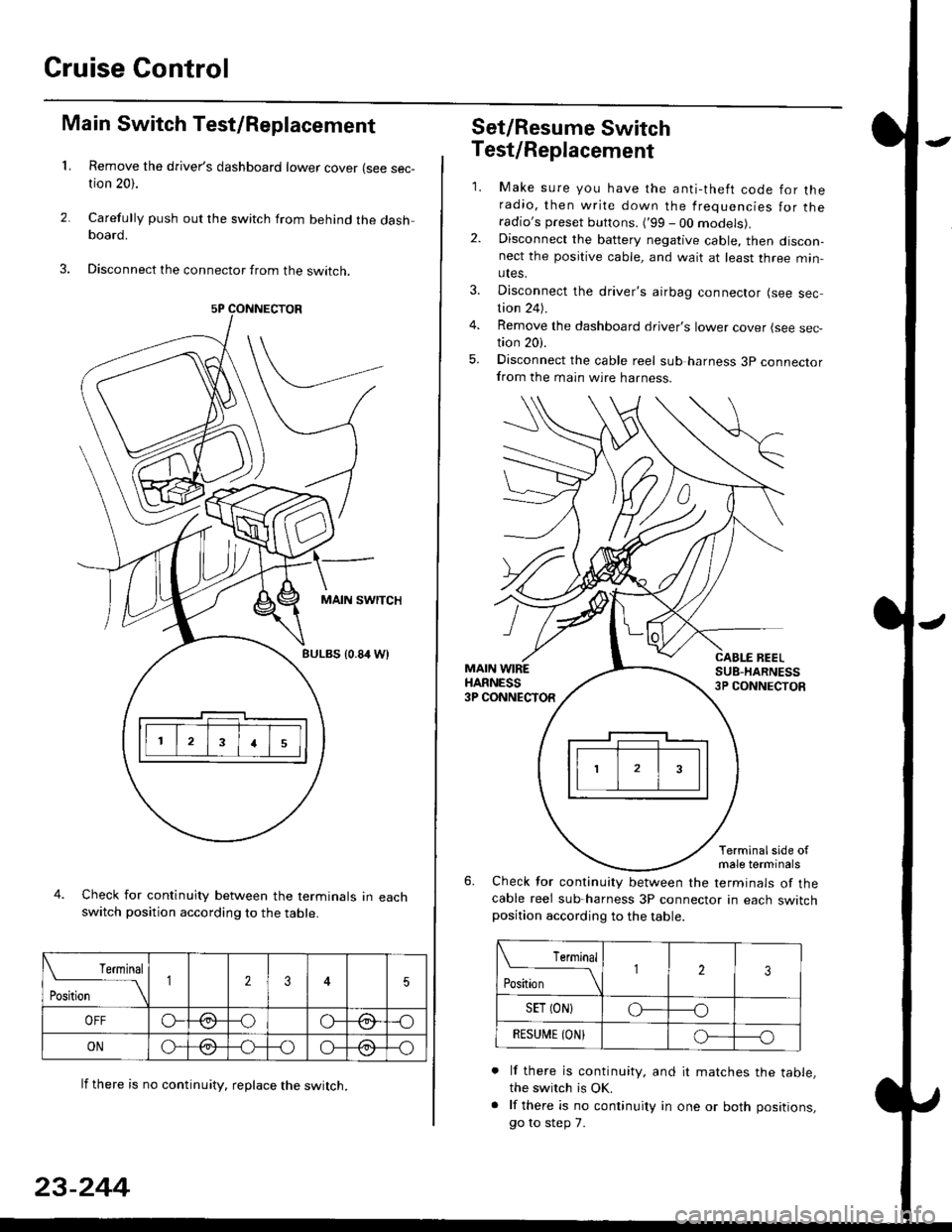
Cruise Gontrol
3.
1.
2.
Main Switch Test/Replacement
Remove the driver's dashboard lower cover (see sec-tion 20).
Carefully push out the switch from behind the dashboard.
Disconnect the connector from the swtrcn.
MAIN SWITCH
BULBS {0.84 Wt
Check for continuity between the terminals in eachswitch position according to the table.
lf there is no continuity. reDlace the switch.
4.
Terminal
r**
--\235
OFFo--oGa\-o\:./\a/
ONo-/a-oo--o\:/\:/
23-244
Set/Resume Switch
5.
Test/Replacement
2.
1.
MAIN WIREHARNESS3P CONNECTOR
Make sure you have the anti-theft code for theradio, then write down the frequencies for theradio's preset buttons. ('99 - 00 models).Disconnect the battery negative cable, then discon-nect the positive cable, and wait at least three min-utes.
Disconnect the driver's airbag connector (see sec-tion 24).
Remove the dashboard driver's lower cover (see sec,tion 20).
Disconnect the cable reel sub harness 3p connectorfrom the main wire harness.
CABLE BEELSUB-HARNESS3P CONNECTOS
Terminalside ofmale terminals
Check for continuity between the terminals of thecable reel sub-harness 3P connector in each switchposition according to the table.
L Terminal
Position123
SET (ON}o----o
BESUi,|E IONIo-----o
lf there is continuity, and it matches the table,the switch is OK.
lf there is no continuity in one or both positions,
go to step 7.
Page 1780 of 2189
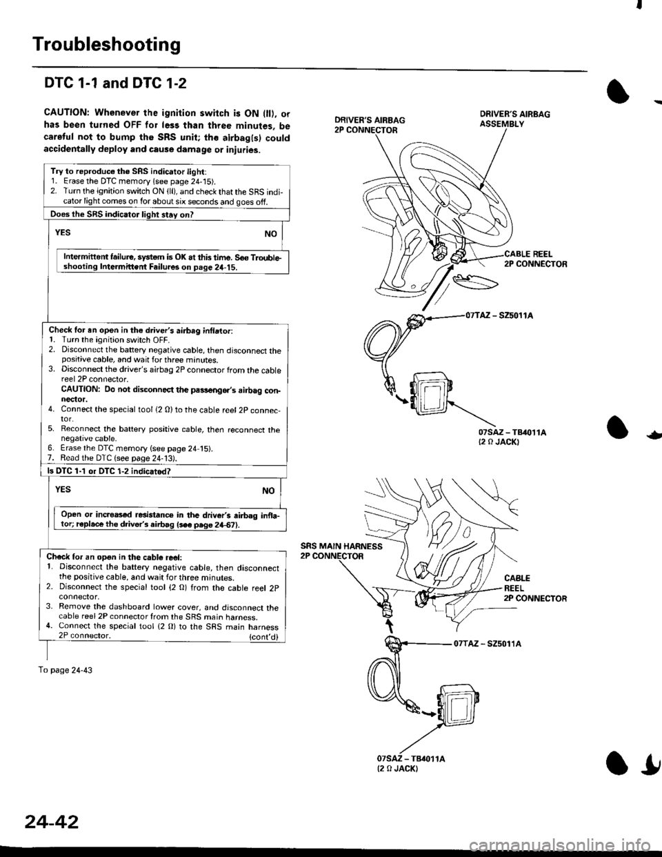
Troubleshooting
DTC 1-1 and DTG 1-2
CAUTION: Whenever the ignition switch is ON 0l), orhas been turned OFF for le33 than three minutes, becareful not to bump the SRS unit; the airbagls) couldaccidentally deploy and cause damage or inluries.
REEL2P CONNECTOR
AZ - SZ5011A
07sAz-TB{0t1At2 0 JACKT-
CABLEREEL2P CONNECTOR
07TAz - SZ5011A
DRIVER'S AIRBAG
SRS MAIN HARNESS
Try to reproduc€ the SRS indicator light:1. Erase the DTC memory lsee page 24,'15).2. Turn the ignition switch ON {ll), and check that the SRS indi-cator light comes on lor about six seconds and goes off.
Does the SRS indicator liqht 3tav on?
Intermittent lailure. system is OK at this time. So€ TloubleIntermittent Failur6 on Deqe 24-15.
Check for en open in th€ driver's airbag inllator:1. Turn the ignition switch OFF.2. Disconnect the battery negative cable, then disconnect thepositive cable, and wait for three minutes.3. Disconnect the driver's airbag 2P connector from the cablereel 2P connector.CAUTION: Do not disconnect the pa9,!eng6.,s ailbag con-nector.4. Connect the special tool {2 0)to the cable reel 2P connec,tor.5. Reconnect the battery positive cable, then reconnect thenegative cable,6. Erase the DTC memory {see page 24 15}.7. Read the DTC {see paqe 24-13).
ls OTC 1-1 or DTC 1-2 indicatod?
Open or incroas€d resistanc€ in the driver's ai.bag inoa-tor; r€place the d ve/s airbag lse6 pege 24€?).
Check for an opgn in the cabl6 reel:1. Disconnect the battery negative cable, then disconnectthe positive cable, and wait for three minutes.2. Disconnect the special tool {2 O) from the cable reel 2pconnector,3. Remove the dashboard lower cover, and disconnect thecable reel 2P connector from the SRS main harness.4. Connect the special tool {2 0} to the SRS main harness2P connector, {cont,
To page 24-43
(2 0 JACK)
24-42
l!
Page 1782 of 2189
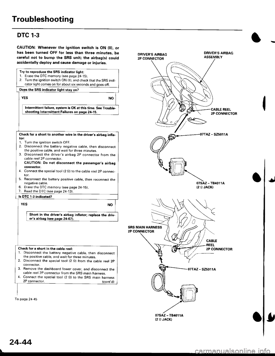
Troubleshooting
DTC 1-3
CAUTION: Whenever the ignition switch is ON {lll, orhas been turned OFF lor less than thrEe minutes, becaroful not to bump the SRS unit; the airbag(s) couldaccidenlally deploy and cause damage 01 iniuries.
DRIVER'S AIRBAGASSEMALY
REEL2P CONNECTOR
AZ - SZ5011A
07saz - TB4011A{2 0 JACK)
CABLEREEL2P CONNECTOR
07TAZ - SZ5011A
TrV to reproduce the SRS indicator light:1. Erase the DTC memory (see page 24-15).2. Turn the ignition switch ON (ll), and check that the SRS indicator light comes on for about six seconds and goes off.
Does the SRS indicalor light stav on?
YESNO
Intermittent lailure. system is OK ai this tim€. Se€ Troubl€-shooting Intermittent Failures on page 24-15.
Check tor a short lo another wire in the drivo.'s eirbrg in{la-
1. Turn the ignition switch OFF.2. Disconnect the battery negative cable, then disconnectthe positive cable, and wait for three minutes.3. Disconnect the driver's airbag 2P connector from thecable reel 2P connector,CAUTION: Do not disconnect the passenger's airb.gconnector,4. Connect the special tool (2 0)to the cable reel 2P connector,5. Reconnect the baftery positive cable, then reconnect thenegative cable,6. Erase the DTC memory (see page 24 15).7. Read the DTC (see page 24-13).
ls DTC 1-3 indicated?
NOYES
Shon in the driver's airbag intlator; replace the driv-er's airbag {see page 24-67}.
Check lor a short in the ceble reel:1. Disconnect the battery negative cable, then disconnectthe positive cable, and wait for three minutes.2. Disconnect the special tool (2 O) from the cable reel 2p
3. Remove the dashboard lower cover, and disconnect thecable reel 2P connector from the SRS marn naroess.4. Connect the special tool (2 O) to the SRS main harness2P coonector. {cont,di
fo page24-45
SRS MAIN HARNESS
24-44
07sAz - TBr011At2 0 JACKI
Page 1786 of 2189
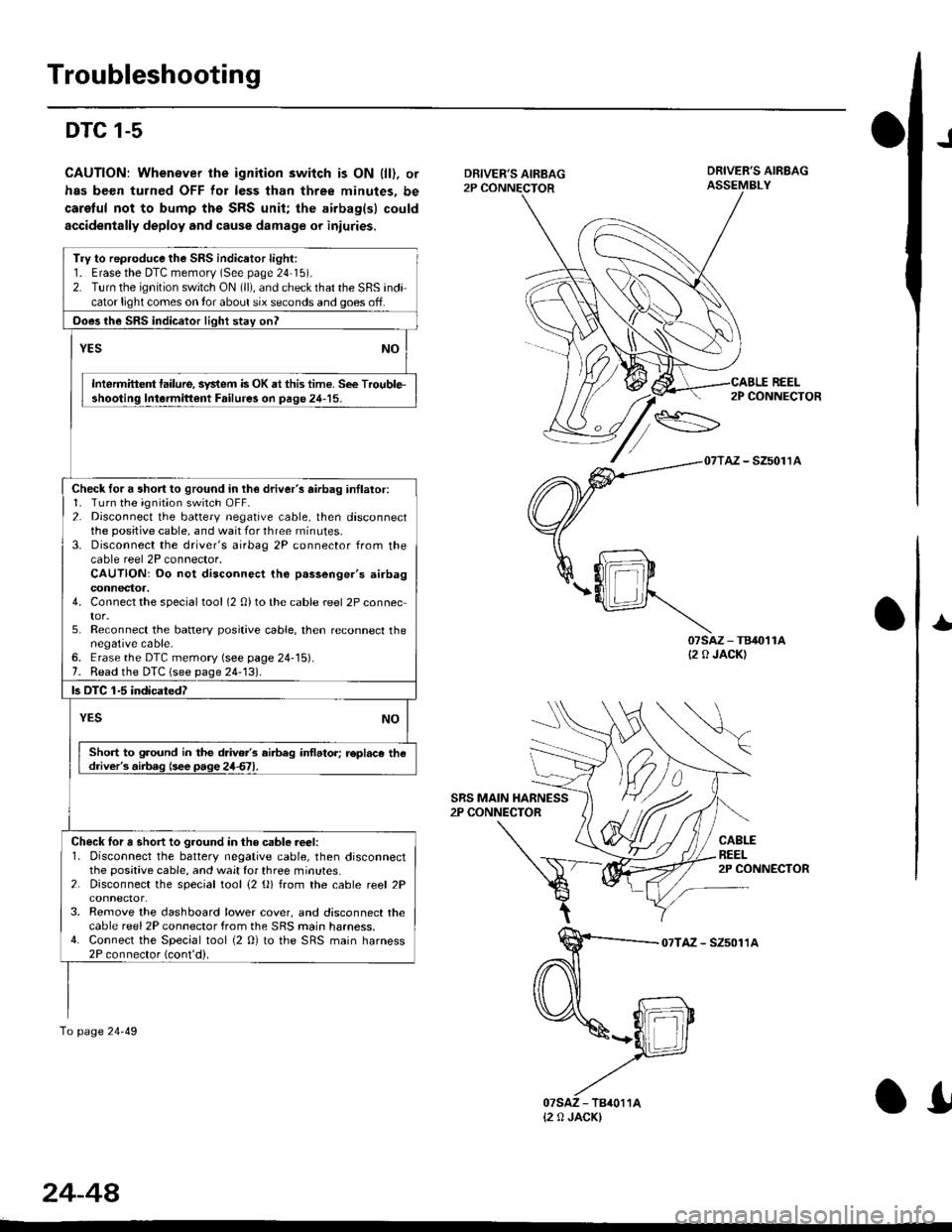
Troubleshooting
DTC 1-5
CAUTION: Whenever the ignition switch is ON {ll). or
has been turned OFF for less than three minutes, be
caretul not to bump ths SRS unit; the airbag(sl could
accidentally deploy and cause damage or iniuries.
J
DRIVER'S AIRBAG2P CONNECTOR
SRS MAIN HARNESS2P CONNECTOR
DRIVER'S AIRBAGASSEMBLY
REEL
07sAz - TB40't1A(2 0 JACK)
2P CONNECTOR
AZ - SZ5011A
CABLEREEL2P CONNECTOR
I
07TAZ - SZ5011A
Try to rep.oduce the SRS indicator light:1. Erasethe DTC memorv (See page 24'15).2. Turn the ignition switch ON (ll), and check that the SRS indicator light comes on tor about six seconds and goes off.
Ooes the SRS indicator light stay onl
YESNO
Intermittent lailure, system is OK at this time. See Trouble-shooting lntormittent Failure3 on page 24-15.
Check for a short to ground in lh€ driver's airbag inllator:1. Turn the ignition switch OFF.2. Disconnect the battery negative cable, then disconnectthe positive cable, and wait for three rninutes.3. Disconnect the driver's airbag 2P connector from thecable reel 2P connector.CAUTION: Do not disconnect tho p.ssenger's airbagconnectoa.4. Connect the specialtool (2 0)to the cable reel 2P connector.5. Reconnect the batlery positive cable, then reconnect thenegative cable-6. Erase the DTC memory (see page 24-15).7. Read the DTC (see page 24-131.
ls OTC 1-5 indicatedT
YESNO
Short to ground in the drive/s airbeg inflator; r€pl.ce thedriver's.iib.g (see page 24d1.
Check lor a short to ground in the csble reer:l. Disconnect the battery negative cable, then disconnectthe positive cable, and wait for three minutes.2. Disconnect the special tool {2 (}) from the cable reel 2P
3. Remove the dashboard lower cover, and disconnect thecable reel 2P connector from the SRS main harness.4. Connect the Special tool {2 0} to the SRS main harness2P connector (cont'd).
To page 24-49
{2 0 JACK)
24-44
.I