Page 1531 of 2189
rt
SRS Main Harness
Conneclor or
Terminal
Number of
CavitiesLocationConnects toNotes
c801
c802
c803
c804
c805
c806
c807
2?
2
2
2
18
Under left side of dash
Above under-dash fuse/relaY
DOX
Right side of under-dash fuse/
relay Dox
Under left side of dash
Under right side of dash
Middle of floor
Middle of floor
Under-dash fuse/relay box (C911)
N4ain wire harness (C412)
Memory erase signal {MES) connector
Cable reel
Passenger's airbag assemblY
Dummy resastor connector
SRS unit
USA
Canada
G801Middle of floorBody ground, via SRS main harness
SRS MAIN HARNESS
23-61
Page 1536 of 2189
Fuses
Under-hood ABS Fuse/Relay Box
lTo under-hood ABS tus€/relay box wire harnossl
c926
lTo main wire harness (C357)l
@27ITo main wir6 harno$ {C356}l
Wire Colol
c92E
[To ABS pump motor relayl
Componont(s) or Circuit(sl ProtsctedFusg Number
6140AWHTABS pump motor (via ABS pump motor relay)
63BRN/YE LABS control unit (motor check)
204WHT/GRNABS control unit (+Bl )
23-66
Page 1546 of 2189
Ground Distribution
Circuit ldentification (conf dl
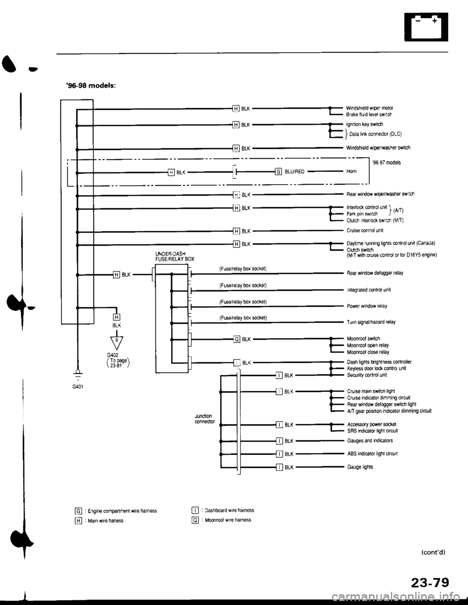
'9&98 models:
(t[oileas6)>{ BRN/BLKLGl II EcM/PcMlcz J
[..........{ BFNaLKCKF sensor jL .-!l 8LU/FED
Knoct s€rlsor (KS)r' ::{ REDtsLU
PimaryH02S*?- wHT
Matnsnafi g]€eo sdnsoa -'1 t I HEL)
Counlersiall speed sensor --={Fl BIU
Ecr#PcM ----Tal WHT/BED
Dive trjiley speed seftsor -1ll FED,ALU
0 ven pulley speed sensor .-lJ WHT
Seconftry gear shalt speed sansor .-!.1 WHT/RED
44:lil
ECIVPCM
)*"Dl6YBengine
Dl6Y5, D16Y7 sngine
vtl
8BM/BLK - IBBi1/BLK _ I^l^1ll'. I rcu rcwr
**' -i IWHT/RED + ]
El , Engln" *lr" h"rn""" - - - - - - : Shietorns
E : Main *re harness
23-76
* 1 :D16Y5,016Y8 engino* 2 : Excepl Dl 6Y5 engine (i//T)+3: D16Y5 engine (Mfi)
Page 1547 of 2189
rt
'99-00 models:
(5i%ease)E>4 BRNiBLK
i.,.,].',,-
ERNi BtK
BRIVBLK
BFN/BLK
BRN/BLK
BRN]BLK
BRIl/8LK
BFN/BLK
r * s r;l ao^r,qt r
CKF s€nsor 1t -1ll ELU/FEU
Knoq( sonsor (r15J '-l !l r{EUl6LU
P maryHo2s*?H wHT
Mainshafl speeo ssnsor -1ll fiEU
Coutershall sp€ed sensor -+F ] BLU) ..",r.u,.0n
016Y7, Dl6Y5 (CW) ongines
;;=-"r,i,-l
Ly"::::::::
I Secondary Ho2s :{ WHT/RED-;'4:v-..1
RED/BLU - I
wHT - f rau,rru (an )
pgTpse- J
*1i016Y5, Dl6Y8engines *4:016Y7, Bl6AzerEines lcont'd)*2: Excepl DI6YSengino ([VT) *5: D16Y5, D16Y7, D16Y8Bngines* 3:Dl6Y5 sngine ([VT) *6:B16M, D16Y8,016Y5 (CW)engines
015Y5 (LVT) sngine
41-.1
Dfiv6 prirEy speeo sonsot -1l l hEL,bLU
Driven gr ley sp€ed sensor -- F I WHT
Secondary gea sian sp€ed sensor .-ll WHT/RED
E : Engine w re harness E : Rear h€al6d orygen sensor sLlb harness
IIJ : Main wire harnsss ------ shielding
816A2, Dl6Ygengiftes
23-77
Page 1549 of 2189

t
'96-98 models:
BLK -..1 |-|d BLIJ/REo - Horn
8LK
J
G402/ To page 23,81
6L^ --...........-- Munn'un' 5.nLi
?_ Moofrootooen retayL MOOnTOOI dose relay
B-(- Dash hghls bfrqrlless co 'oel
l- ftyess door to* mnlror Lnil-llerX + Seorriry @rl'ol Jn :
JUndonconnedor
BLK
BLK
BLK
Cnrise main swilch lighlCruise indicalor dirnming orcuilRed window deloggel swilch lighlA/T gear posilion indicalor dimming cilo./il
Accessory power sockelSRS indicalor lighl circlil
Cauges end indicatols
ABS indicalor lighl cirq)rl
Gauge lights
El : Engine companmenl wire harness
E , M"in *it" h"n"..
E : oashboatd w€ haness
@ : Moonrool w re harness
UNOEB,DASHFUSE/RELAY BOX
EL^ - YY'iisnEo 'F€ "'v'u'- Bfale llJ d levetswlci
qq.-_
E I Dah Inl col"eclot 'D-cl
Windshield w perhvasher swildr
--l ,o ,? '.da.
Rear window wip€r^vasher swtch
'''"_- -- , rA/Tll_ paa pirswilcF t-,l- Clulcf nlel ock sw lcr rVT)
Cruise conlrol unil
8LK - Da,'lm€ runnrng lrghts conltol unil (CanaJa)
(Fuserelay box sockel)
(Flserelay bor sockel)
(Fuse/relay box socke0
(Fuse/relay box sockel)
BLK-
(M/T wilh cruise conlfol or lor D16Y5 erEine)
Bear window delogger relay
Lnlegrated conlrol unil
Turn signal/hazad @lay
(cont'd)
23-79
oot
Page 1550 of 2189

Ground Distribution
Circuit ldentification (conf d)
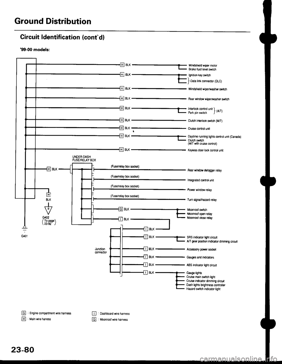
'99-00 models:
EWir'rdshield wipe. nolorBGke lluid level swildl
6L^ -- €nrnon €y sv loa-)l- i oala hnk conn€clol lDlcl
8LK
BLK
Windshigld dper^vash€r switdt
Re windo wiperlflasher ssitch
BLK
J
To 9aqe23.A2-
tr
E
UNOEN.DASHFUSgRELAYSOX
-r^ -..-- tmenoo( @ rotunn l ._.l- pa* oin swhrh l\4tl
ClLrldr inlerlod swildr (M,T)
Cruis€ confol unit
BL( ---- Oay me running tights controtund (Canadal_ Ctuldt sfich(l,t/T vrith ruis€ cor rol)
Key'ess door lock control unit
(Fuserelay box sockst)
(Fus€/relay box sod(8t)
(Fusdrelay bor sockel)
(Fuserelay box sock€l)
8LK
BLK
BLK
BLK
8LK
near windoYr delogger rclay
htograted co.Ird unil
Tum signal/hazard lelay
SRS indicalor lighl cirqtil,y'T goer position indicator dimming cirdlit
Accessory poxer sod@l
Gaug€s and indicators
ABS indicalor light ciro.lil
Gauge lighbCruis€ main swil$ lEhlCruiso indicator dimming ciroritoash lohls brighlness confolbtHazard s$tdl indicator liohl
G401
(
oh --- Moonroot swnm
t- iroonrool open relay- Moonroot dose reiay
t
fil BLK -J
: Engine @mparlrnenl wire hamess
: Main wire haness
,JUncll0n@nfreclol
E : Dashboard wire harness
El , Mo*tool *ite har"..
23-80
Page 1552 of 2189
Ground Distribution
Circuit ldentification (cont'dl
'99-00 models:(Wilholl ABS)
r'1BL( -< 6 | c40. tFror oaoe 23-BC. II
L
E
UNDEF.H@DFUSF]RELAY BOX
_::I
A,/I gefi posilion swilchELD unil
Servi@ check connector
BL-_14BL- rl--{ry--Browe,mororreray
L4 ,r^ -.;--a-r,* -11-51 BLK - Hearer conrror o6nt n"*-fi-+aLx-lfuBLK- Hearer conrror panel
eLx -iff BLK - ff;?,m",:[:' "n'
or*
ABS glmp motor
_trl
G501
Pos€r door lock cortaol unitDivers door lock aclualorDriver's door lock switchLefl miror delogger
BLK --.+t _
F J Power wndos man swdch
-. Dive/s Fo*gr window motor
TBLK -.1 F--{ BLK - Fighr.niror detogger
tr
tr
E : Healer sub-haness A
El : Healer sub'harress B
: Floor wire hamess
: Drve/sdoorwife haness
-
|,-"*T-"^tl I
vl-L"."
G551
ort,
El ' Main *it" hanes
E : Dashboafd wirc harness
23-82
@ Passenger's doof w're hamess
Page 1559 of 2189

lgnition Switch
4.
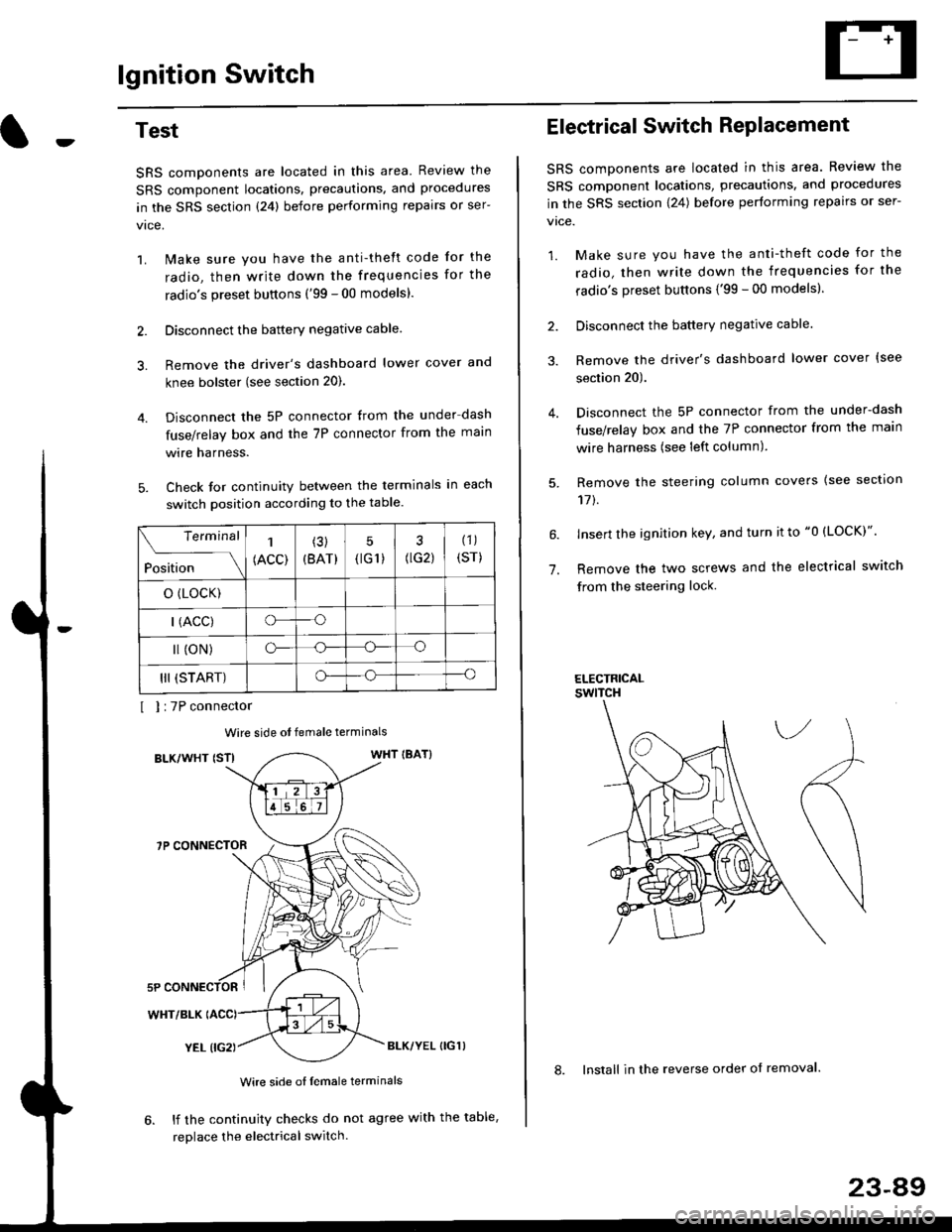
Test
SRS components are located in this area Review the
SRS component locations. precautions. and procedures
in the SRS section {24} before performing repairs or ser-
1. i/ake sure you have the anti-theft code for the
radio, then write down the frequencies for the
radio's preset buttons ('99 - 00 models).
2. Disconnect the battery negative cable.
3. Remove the driver's dashboard lower cover and
knee bolster (see section 20).
Disconnect the 5P connector from the under dash
fuse/relay box and the 7P connector from the main
wire harness.
Check for continuity between the terminals in each
switch position according to the table.
I I :7P connector
Wire side ot female terminals
BLK/WHT {STIWHT IBAT}
7P CONNECTOR
WHT/BLK
YEL (IG2}BLK/YEL {IG1)
Wire side of female terminals
6. lf the continuity checks do not agree with the table,
replace the electrical switch.
Terminal
Position
1
(ACC)
(3)
(BAT)
5
{tG1) G2)
(1)
(sr)
o (LocK)
| (ACC)o--o
l (oN)o-o
III (START)o--o
1.
Electrical Switch RePlacement
SRS components are located in this area. Review the
SRS component locations, precautions, and procedures
in the SRS section \24) belore performing repairs or ser-
vtce.
1. Make sure you have the anti-theft code for the
radio, then write down the frequencies for the
radio's preset buttons {'99 - 00 modelsl.
2. Disconnect the battery negatlve cable.
3. Remove the driver's dashboard lower cover {see
section 20).
Disconnect the 5P connector from the under-dash
fuse/relay box and the 7P connector from the main
wire harness (see left column).
Remove the steering column covers {see section
11t.
lnsert the ignition key, and turn it to "0 {LOCK)".
Remove the two screws and the electrical switch
from the steering lock.
ELECTRICALswtTcH
8. Install in the reverse order of removal.
23-a9