1996 HONDA CIVIC Ckf
[x] Cancel search: CkfPage 1488 of 2189
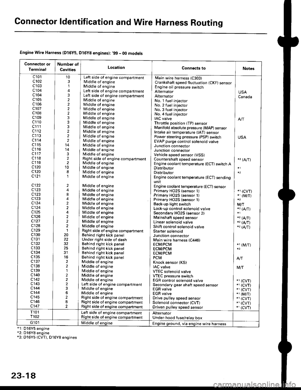
Gonnector ldentification and Wire Harness Routing
Engine Wire Harness (D16Y5, Dl6Yg engines): ,99 - 00 models
Connectot or
Terminal
Number ot
CavitiesLocationConn€cts toNotes
c'101cl02c103c104c 104c10s
c107c 108c'r09c110c111cl12c113cl14c l15c116cl17c118c119c120cl20c121
c122c123c123cl23cl24c124c125
c127c12Ac129c 130c131cl32c133c 134c135c137c138c 139c 140c142c143c144cl44c145c146c147
103,]
322223332221414322'10
8,l
2484224222120
32
2212223
282
No. 1 luel injector INo.2 fuel injectorNo.3 fuel injector ]No. 4 fuel injector iIAC valve I anThrottle position lTP) sensorManifold absolute pressure {MAP) sensor IIntake air temperature (lAT) sensor IPower steering pressure (PSP)switch USAEVAP purge control solenoid valve ]
Main wire harness 1C303)Crankshaft speed fluctuation (CKF) sensorEngine oil pressure switchAlternatorAlternator
Left side ot engine compartmentlvliddle of engineMiddle of engineLeft side ot engine compartmentLeft side of engine compartmentMiddle of engineMiddle ot engineMiddle of engineMiddle of engineMiddle oI engineMiddle of engineMiddle of engineMiddle of engineMiddle of engineNliddle of engineMiddle of engineMiddle of engineMiddle of engineRight side of engine compartmentMiddle of engineMiddle of engineN4iddle of engineMiddle of engine
Middle of engineMiddle ot engineMiddle ot engineMiddlo of engineMiddle of engineMiddle ot enginelrliddle of engineMiddle of engineMiddle oI engineMiddle ot engineRight side of engine compartmenlBehind right kick panelUnder right side of dashBehind right kick panelBehind right kick panelBehind righr kick panelBehind right kick panelMiddle ot engine[,liddle of engineN4iddle of engineMiddle of engineMiddle oI engineLeft side of engine compartmentMiddle of engineMiddle of engineRight side ol engine compartmentRight side of engine companmentRight side of engine compartment
USACanada
Junction connectorJUnct|On COnnectorVehicle speed sensor lVSS)Countershaft speed sensorEngine coolant temperature {ECT} switch ADistributorDistributorEngine coolant temperature (ECT) sendingunitEngine coolant temperature (ECT) sensorPrimary H02S (sensor 1)Primary HO2S (sensor 1)Primary HO2S lsensor 1)Back-up light switchLock'!p control solenoid valveSecondary HO2S (sensor 2)Mainshaft speed sensorLinear solenoid valveShift control solenoid valveStarter solenoidJunction connectorMain wire harness (C446)ECM/PCMECM/PCMECM/PCMPCtvtKnock sensor (KS)IAC valveVTEC solenoid valveVTEC pressure switchEGR control solenoid valveSecondary gear shaft speed sensorEGR valveEGR valveDrive pulley speed sensorSolenoid connector (CVT)Driven pulley speed sensor
*'� (A/TI
*1 (CVT)*, (M/T)
Mfia (A/Tl
" (A,/T)., (4,/r)-'� {AlrJ
*1 (M/T)
tvliT
*1 (CVT)*, (cvT)*' (cw)*1 (MiT)*1 {CVT)*1 {CVT)*, (cvr)
T101T102Left side of engine companmentRight side ot engine companmentAlternatorUnder'hood fuse/relay boxG 101Middle of englne IEngine ground, via engine wire harness*1: 016Y5*2: D16Y8*3: Dl6Y5
engineengine(CW), D16Y8 engines
23-14
Page 1490 of 2189
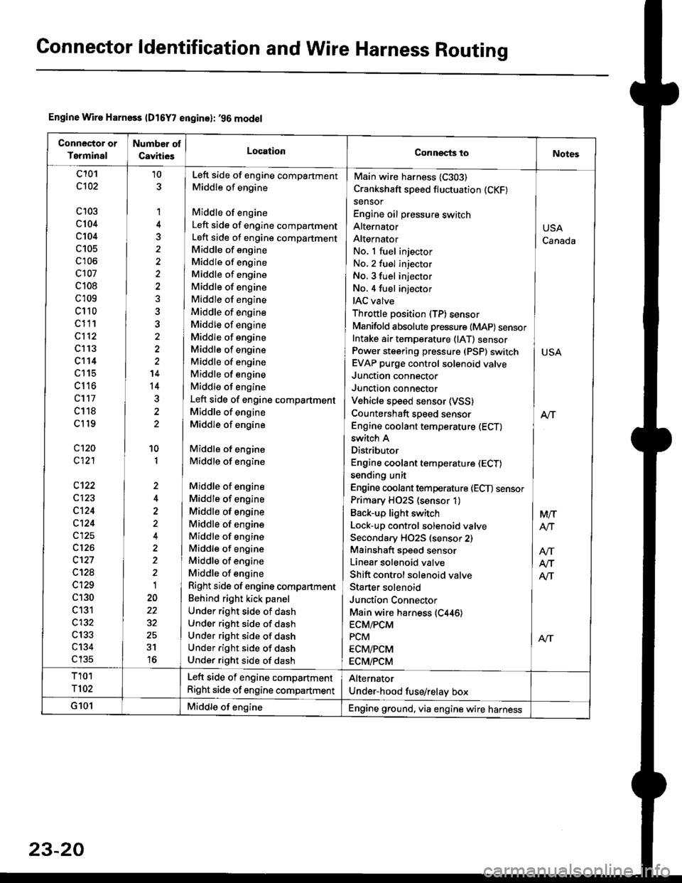
Gonnector ldentification and Wire Harness Routing
Engine Wire Harness {D16Y7 engine}: '96 model
Conneclor or
Terminal
Number ot
CavhiesLocationConnects toNotes
c101
c102
c 103
c104
c104
c105
c'r06
c107
c 108
c 109
c110
c111
c112
c l13
c't14
LttS
cl16
cl17
c118
cl19
c120
c121
c123
c124
c124
c125
c126
c't27
c12a
c129
c130
c131
c132
c133
c134
c135
10
1
4
5
'14
14
10
1
,,
2
2
1
22
31
16
No. 1 fuel injector INo. 2 fuel injector
No. 3 fuel injector INo,4 fuel injector
IAC valve l
Throttle position (TP)sensor IManifold absolute pressure (MAP) sensorIntake ai. temperature (lAT) sensor ]Power steering pressure (PSP) switch I USAEVAP purge control solenoid valve IJunction connector
Junction connector IVehicle speed sensor (VSS) |Countershaft speed sensor AlTEngine coolant temperature (ECT) I
Main wire harness (C303)
Crankshaft speed fluctuation (CKF)
sensor
Engine oil pressure switch
Alternator
Alternator
switch A
Distributor
Engine coolant temperature (ECT)
sending unit
Engine coolant temperature lECT) sensor
Primary H02S (sensor 1)
Back-up light switch
Lock-up control solenoid valve
Secondary HO2S (sensor 2)
Mainshaft speed sensor
Linear solenoid valve
Shift control solenoid valve
Staner solenoid
Junction Connector
Main wire harness {C446)ECM/PCM
PCM
ECM/PCM
ECM/PCM
Left side of engine compartment
Middle of engine
Middle of engine
Left side of engine compartment
Left side of engine compartment
Middle of engine
Middle of engine
Middle of engine
Middle of engine
Middle of engine
Middle of engine
Middle of engine
Middle of engine
Middle of engine
Middle of engine
Middle of engine
Middle of engine
Left side of engine compartment
Middle of engine
Middle of engine
Middle of engine
Middle of engine
Middle of engine
Middle of engine
Middle of engine
Middle of engine
Middle of engine
Middle of engine
Middle of engine
Middle of engine
Right side of engine compartment
Behind right kick panel
Under right side of dash
Under right side of dash
Under right side of dash
Under right side of dash
Under right side of dash
USA
Canada
M/T
AtJ
Afi
T101
T102
Left side of engine compartment
Right side of engine compartment
Alternator
Under-hood fuse/relay box
G101Middle of engineEngine ground, via engine wire harness
23-20
Page 1492 of 2189
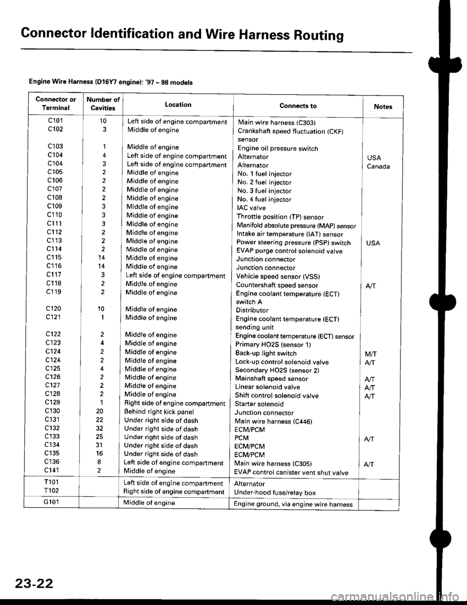
Connector ldentification and Wire Harness Routing
Engine Wire Harness {Dt6Y7 enginel: '97 - 9g models
Connectot or
Terminal
Number of
CsvitiesLocationConnects toNotes
c 101
c102
c103
c104
c104
c105
c106
c107
c 108
c109
cl10
clll
c112
cl13
cl14
c115
c1 l6
c117
c118
cl 19
cl20
c121
c122
c123
cl24
c124
c125
c126
c127
c128
c129
c 130
c 131
c132
c134
c135
cl41
10
1
2
10
I
2
2'>
4
t
20
3r
2
No. l fuel injector
No.2 fuel injector
No. 3 fuel injector INo. 4 fuel injector
IAC valve ]Throttle position (TP) sensor IManifold absolute pressure (MAP) sensorIntake air temperature (lAT) sensor ]Power steering pressure (PSp) switch I USAEVAP purge control solenoid valve
Junction connector IJunction connector IVehicle speed sensor (VSS)
Countershaft speed sensor I enEngine coolant temperature (ECTI
Main wire harness (C303)
Crankshaft speed fluctuation (CKF)
sensor
Engine oil pressure switch
Alte|'nator
Alternator
switch A
Distributor
Engine coolant temperature (ECT)
sending unit
Engine coolant temperature (ECT) sensor
Primary HO2S (sensor 1)
Back-up light switch
Lock-up control solenoid valve
Secondary H02S (sensor 2)
Mainshaft speed sensor
Linear solenoid valve
Shift control solenoid valve
Staner solenoid
Junction connector
Main wire harness (C446)
Left side of engine compartment
Middle of engine
Middle of engine
Left side of engine compartment
Left side of engine compartment
Middle of engine
Middle of engine
Middle of engine
Middle of engine
Middle of engine
Middle of engine
Middle of engine
Middle of engine
Middle of engine
Middle of engine
Middle of engine
Middle of engine
Left side of engine compartment
Middle of engine
Middle of engine
Middle of engine
Middle of engine
Middle of engine
Middle of engine
Middle of engine
Middle of engine
Middle of engine
Middle of engine
Middle of engine
Middle of engine
Right side of engine compartment
Behind right kick panel
Under right side of dash
Under right side of dash
Under right side of dash
Under right side of dash
Under right side of dash
Left side of engine compartment
Middle of engine
USA
Canada
Mtr
AIT
ECM/PCM
PcM I ArrECM/PCM
ECM/PCM
Main wire harness {C305) | AftEVAP control canister vent shut valve
T 101
r102
Left side of engine compartment
Right side of engine companment
Alternator
Under-hood fuse/relay box
G 101Middle of engineEngine ground, via engine wire harness
23-22
Page 1494 of 2189
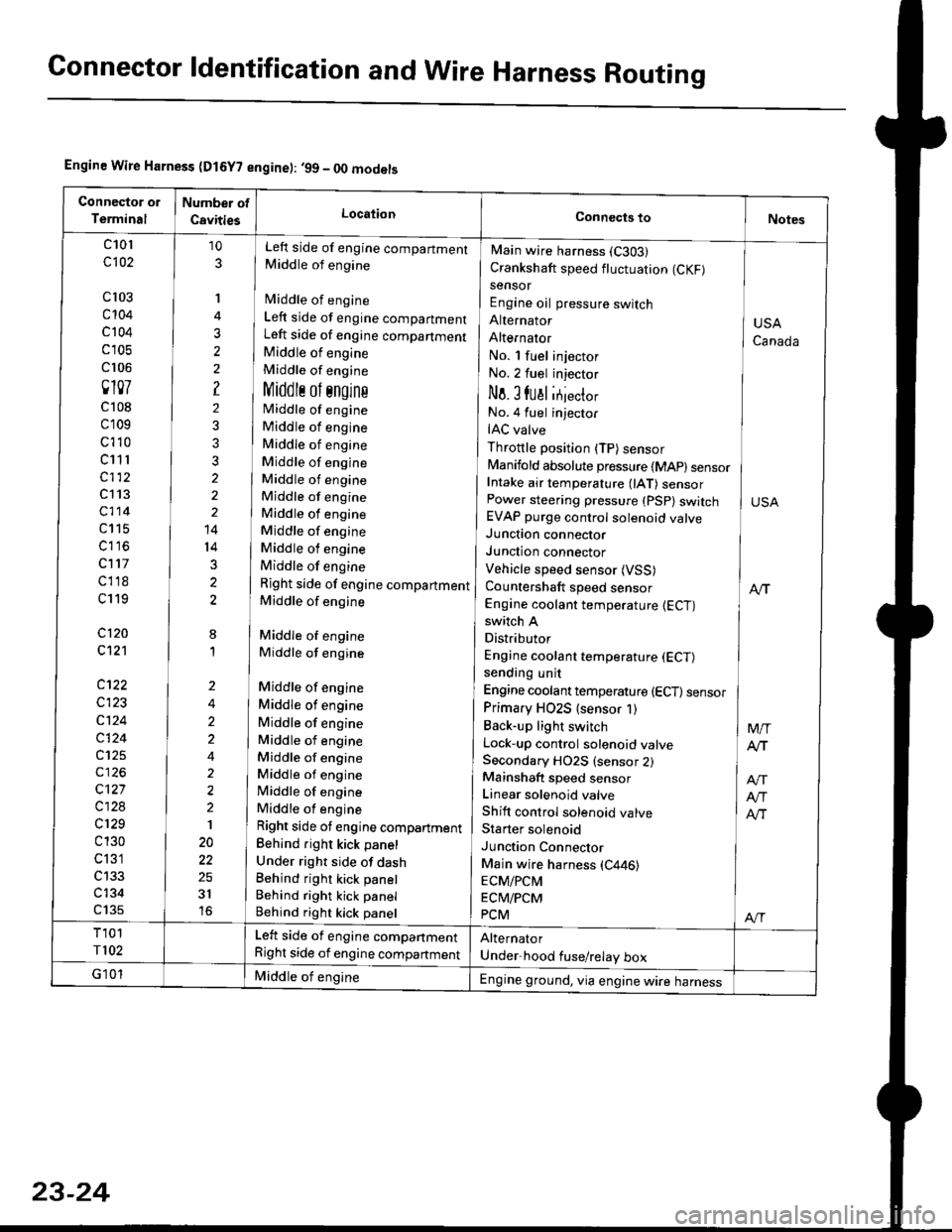
Connector ldentification and WireHarness Routing
Engine Wire Harness (D15Y? engine): ,99 - OO models
c101
c102
cl03
c't04
c 104
c 105
cr 06
0107
c108
c109
c't 10
c11 r
c112
c113
c114
c115
c116
c117
cl18
c119
c120
c121
c122
c123
c124
c124
c125
c127
c128
c129
c 130
c 131
c134
c135
10
3
'I
3
?
2
3?
2
14
14
3
2
8
1
Left side of engine compartment
Middle of engine
fvliddle of engine
Left side of engine compartment
Left side of engine companment
Middle of engine
Middle of engine
Middlr ol sngins
Middle of engine
Middle of engine
Middle of engine
Middle of engine
Middle of engine
Middle of engine
Middle of engine
Middle of engine
Middle of engine
Middle of engine
Right side of engine compartment
Middle of engine
Middle of engine
Middle of engine
Middle of engine
Middle of engine
Middle of engine
Middle of engine
Middle of engine
Middle of engine
Middle of engine
Middle of engine
Right side ot engine compartment
Behind right kick panel
Under right side of dashBehind right kick panel
Behind right kick panel
Behind right kick panel
Main wire harness (C303)
Crankshaft speed fluctuation (CKF)
sensor
Engine oil pressure switch
Alternator
AlternatOr
No. l fuel injector
No.2 fuel injector
No. I fual itjecto,
No.4 fuel injector
IAC valve
Throttle position (TP) sensor
Manifold absolute pressure {MAp) sensorIntake air temperature 0AT) sensorPower steering pressure (PSp) switchEVAP purge control solenoid valveJunction connector
Junction connector
Vehicle speed sensor (VSS)
Countershaft speed sensor
Engine coolant temperature {ECT)switch A
Distributor
Engine coolant temperature (ECT)
sending unit
Engine coolant temperature (ECT) sensor
Primary HO2S (sensor 1)
Back-up light switch
Lock-up control solenoid valveSecondary HO2S (sensor 2)Mainshaft speed sensor
Linear solenoid valve
Shift control solenoid valve
Starter solenoid
Junction Connector
Main wire harness (C446)
ECM/PCM
ECM/PCM
PCM
USA
Canada
M/T
Atr
Atr
Alr
Al-|.
Left side of engine compartment
Right side of engine compartment
Middle of engineEngine ground, via engine wire harness
23-24
Page 1496 of 2189
Connector ldentification and WireHarness Routing
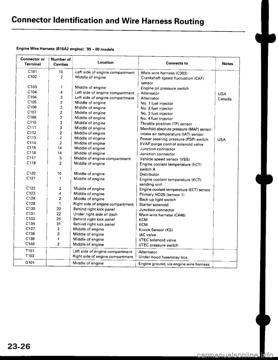
Engine Wire Harness {81642 engine}: .99 - 00 models
c 101
c102
cl03
c104
c 104
c'105
c106
cl01
c108
c110
cl11
cl12
c1'13
c114
c115
c117
cl19
c120
c121
c122
c123
c124
c129
c130
c l31
c133
c134
c137
c 138
c139
c140
Left side of engine companment
Middle of engine
Middle of engine
Left side of engine compartment
Left side of engine compartmentlvliddle of engine
Middle ot engine
Middle of engine
Middle of engine
Middle of engine
Middle of engine
Middle ot engine
Middle of engine
Middle of engine
Middle of engine
Middle of engine
Middle of engine compartment
Middle of engine
Middle of engine
Middle of engine
lMiddle of engine
Middle of engine
Middle of engine
Right side of engine compartment
Behind right kick panel
Under right side of dash
Behind right kick panel
Behind right kick panel
Middle of engine
Middle ot engine
lMiddle of engine
Middle of engine
10
2
,]
4
3
2
2
2
2
3
3
2
2
2
14
14
3
2
'10
'I
2
4
2
1
20
22
25
31
2
2
I
Main wire harness (C303)
Crankshaft speed fluctuation (CKF)
sensor
Engine oil pressure switch
Alternator
Alternator
No. 1 fuel injector
No. 2 tuel injector
No. 3 fuel injector
No. 4 fuel injector
Throttle position (TP) sensor
Manifold absolute pressure (MAP) sensorIntake air temperature (lAT) sensorPower steering pressure (PSP) swjtchEVAP purge control solenoid valve
Junction connector
Junction connector
Vehicle speed sensor (VSS)
Engine coolant temperature (ECT)
switch A
Distributor
Engine coolant temperature (ECT)
sending unit
Engine coolant temperature {ECT) sensorPrimary HO2S (sensor 1)
Back-up light switch
Starter solenoid
Junction connector
Main wire harness (C446)
ECM
ECtvl
Knock Sensor {KS)IAC valve
VTEC solenoid valve
VTEC pressure switch
USA
Canada
Left side of engine companment
Right side of engine compartment
Engine ground, via engine wire harness
Page 1546 of 2189
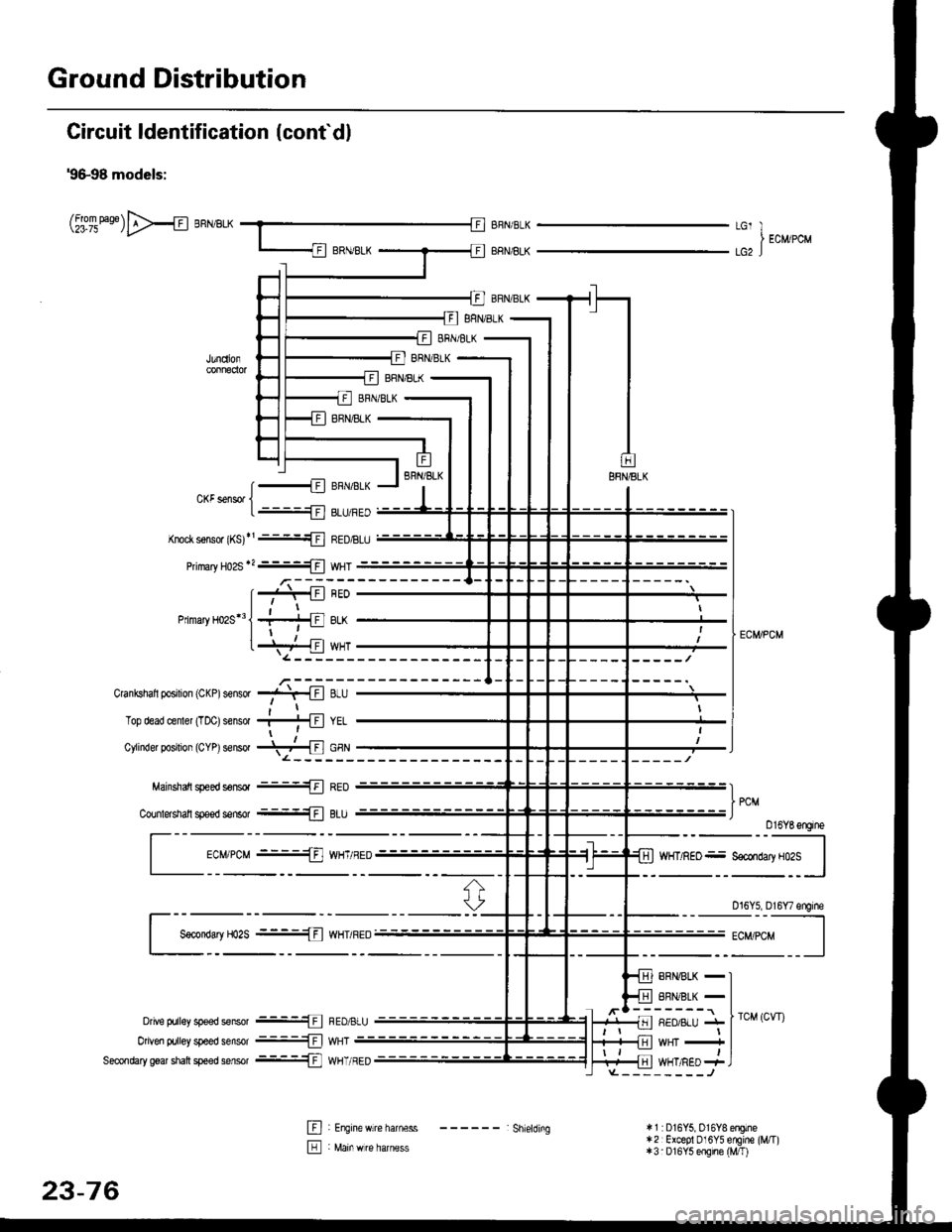
Ground Distribution
Circuit ldentification (conf dl
'9&98 models:
(t[oileas6)>{ BRN/BLKLGl II EcM/PcMlcz J
[..........{ BFNaLKCKF sensor jL .-!l 8LU/FED
Knoct s€rlsor (KS)r' ::{ REDtsLU
PimaryH02S*?- wHT
Matnsnafi g]€eo sdnsoa -'1 t I HEL)
Counlersiall speed sensor --={Fl BIU
Ecr#PcM ----Tal WHT/BED
Dive trjiley speed seftsor -1ll FED,ALU
0 ven pulley speed sensor .-lJ WHT
Seconftry gear shalt speed sansor .-!.1 WHT/RED
44:lil
ECIVPCM
)*"Dl6YBengine
Dl6Y5, D16Y7 sngine
vtl
8BM/BLK - IBBi1/BLK _ I^l^1ll'. I rcu rcwr
**' -i IWHT/RED + ]
El , Engln" *lr" h"rn""" - - - - - - : Shietorns
E : Main *re harness
23-76
* 1 :D16Y5,016Y8 engino* 2 : Excepl Dl 6Y5 engine (i//T)+3: D16Y5 engine (Mfi)
Page 1547 of 2189
![HONDA CIVIC 1996 6.G Workshop Manual rt
99-00 models:
(5i%ease)E>4 BRNiBLK
i.,.,].,,-
ERNi BtK
BRIVBLK
BFN/BLK
BRN/BLK
BRN]BLK
BRIl/8LK
BFN/BLK
r * s r;l ao^r,qt r
CKF s€nsor 1t -1ll ELU/FEU
Knoq( sonsor (r15J -l !l r{EUl6LU
P maryH HONDA CIVIC 1996 6.G Workshop Manual rt
99-00 models:
(5i%ease)E>4 BRNiBLK
i.,.,].,,-
ERNi BtK
BRIVBLK
BFN/BLK
BRN/BLK
BRN]BLK
BRIl/8LK
BFN/BLK
r * s r;l ao^r,qt r
CKF s€nsor 1t -1ll ELU/FEU
Knoq( sonsor (r15J -l !l r{EUl6LU
P maryH](/manual-img/13/6068/w960_6068-1546.png)
rt
'99-00 models:
(5i%ease)E>4 BRNiBLK
i.,.,].',,-
ERNi BtK
BRIVBLK
BFN/BLK
BRN/BLK
BRN]BLK
BRIl/8LK
BFN/BLK
r * s r;l ao^r,qt r
CKF s€nsor 1t -1ll ELU/FEU
Knoq( sonsor (r15J '-l !l r{EUl6LU
P maryHo2s*?H wHT
Mainshafl speeo ssnsor -1ll fiEU
Coutershall sp€ed sensor -+F ] BLU) ..",r.u,.0n
016Y7, Dl6Y5 (CW) ongines
;;=-"r,i,-l
Ly"::::::::
I Secondary Ho2s :{ WHT/RED-;'4:v-..1
RED/BLU - I
wHT - f rau,rru (an )
pgTpse- J
*1i016Y5, Dl6Y8engines *4:016Y7, Bl6AzerEines lcont'd)*2: Excepl DI6YSengino ([VT) *5: D16Y5, D16Y7, D16Y8Bngines* 3:Dl6Y5 sngine ([VT) *6:B16M, D16Y8,016Y5 (CW)engines
015Y5 (LVT) sngine
41-.1
Dfiv6 prirEy speeo sonsot -1l l hEL,bLU
Driven gr ley sp€ed sensor -- F I WHT
Secondary gea sian sp€ed sensor .-ll WHT/RED
E : Engine w re harness E : Rear h€al6d orygen sensor sLlb harness
IIJ : Main wire harnsss ------ shielding
816A2, Dl6Ygengiftes
23-77
Page 1707 of 2189
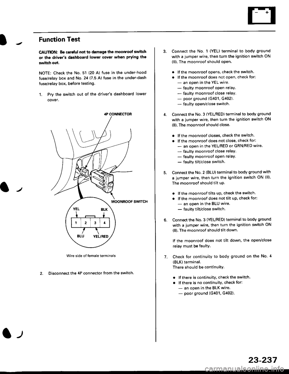
Funstion Test
CAUTION: Bo careful not to damago the moonroof switch
or ths driv6r's dashboard lowsr cover when prying the
3witch out.
NOTE: Check the No. 51 (20 Al fuse in the under-hood
tuse/relay box and No.24 (7.5 A) fuse in the under-dash
fuse/relay box, before testing.
1. Prv the switch out of the driver's dashboard lower
cover.
swtTcH
Wire side of female terminals
2. Disconnect the 4P connector from the switch
4P CONNECTOR
l-t
23-237
Connect the No. 1 (YELI terminal to body ground
with a jumper wire, then turn the ignition switch ON
(ll). The moonroof should open.
. lf the moonroot opens, check the switch.
. lf the moonroot does not open, check for:
- an open in the YEL wire.
- faulty moonroof open relay.
- faulty moonroof close relay,
- poor ground (G401, G402).- fa u lty open/close switch.
Connect the No. 3 (YELnED) terminal to body ground
with a jumper wire. then turn the ignition switch ON
(ll). The moonroof should close.
. lf the moonroof closes. check the switch.
. lf the moonrool does not close, check for:
- an open in the YEURED or GRN/RED wire'
- faulty moonroof close relaY.
- faulty moonroot oPen relaY.
- faulty tilvclose switch.
Connect the No. 2 (BLU) terminal to body ground with
a jumper wire, then turn the ignition switch oN (ll).
The moonroof should tilt up.
. lf the moonroof tilts up, checkthe switch.
. lf the moonroof does nottilt up, checkfor:
- an open in the BLU wire.
- taulty tilvclose switch
Connect the No. 3 (YEURED) terminal to bodY ground
with a jumper wire, then turn the ignition switch ON
(ll), The moonroof should tilt down.
lf the moonroof does not tilt down, the open/close
relay must be taulty.
Check for continuity to body ground on the No. 4
{BLK}terminal.
There should be continuity.
. lf there is continuity, check the switch
. lf there is no continuity, check for:
- an open in the BLK wire
- poor ground (G401, G402).
6.
7.