Page 981 of 2189

Transmission
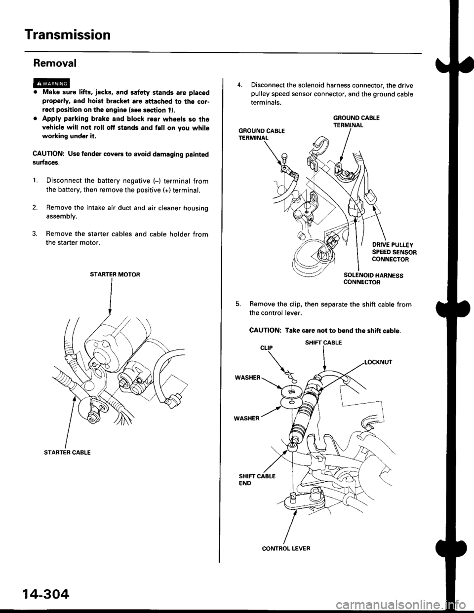
Removal
@. Mako suro lifts. iacks, and satety stands are placod
properly, and hoi3t bracket are attached to lhe cor-
rect position on the engine {see soction 1}.
. Apply parking brake and block r€ar wheels so tha
vehicle will not roll off stands and fall on you while
working undor it.
CAUTION: Use tender covers to avoid damaging painted
surfaces.
Disconnect the battery negative (-) terminal from
the battery, then remove the positive (+)terminal.
Remove the intake air duct and air cleaner housing
1.
assembly.
3. Remove the starter cables and cable holder from
the starter motor.
STARTER CABLE
STARTER MOTOR
14-304
4, Disconnect the solenoid harness connector, the drivepulley speed sensor connector, and the ground cable
terminals.
DRIVE PULI.-EYSPEED SENSORCONNECTOR
SOLENOIO HARNESSCONNECTOR
Remove the clip, then separate the shift cable from
the control lever,
CAUTION: Take care not to bend the shift cable.
WASHER
WASHER
GROUND CABLE
GROUND CAELE
CONTROL LEVER
S}IIFT CABLE
Page 982 of 2189
I
6. Disconnect the vehicle speed sensor (VSS) connec-
tor, the driven pulley speed sensor connector, and
the secondary gear shaft speed sensor connector.
SECONDARY GEARSHAFT SPEEDORIVEN PULLEY
SPEED SENSORCONNECTORSENSOR
7. Remove the transmission housing mounting bolts.
14-305
8. Remove the drain plug, and drain th€ CVT fluid
Reinstall the drain plug with a new sealing washer.
CAUTION: While installing the drain plug' bo 3ur.
nol io allow du3l 8nd other toreign particles to
enter into th€ trsnsmi$ion.
DRAIN PLUG18 x 1.5 rnm(, N.m (5.0 kgfm, 36 lbf'ft|
9. Remove the splash shield.
SEALING WASHERReplaco.
Page 986 of 2189
O ATF DIPSTICK
O o-RING Replace.
.' SOLENOID HARNESS CONNECTOR
@ LOWER VALVE BODY ASSEMBLY
O DOWEL PIN
O LINE BOLT
.i ATTf COOUR IruIET LINE B8ACKET BOLT
€] lrr cooua truler LINE ASSEMBLY
O SEALING WASHER RePIACE'
G, ATF COOLER OUTLET PIPE
6) o-RING Replace.
@ ATF FILTER
fO o-RING Replace.
@ ATF PAN(3 DOWEL PIN(D O-RING Replace.
E) ATF STRAINER
@ ATF MAGNET(9 ATF PAN GASKET RePIACE'
O ATF MAGNET
€t oRAIN PLUG
@ SEALING wAStlER Replace.
TOROUE SPECIFICATIONS
Bolt/Nut No.Torque ValueSizeRemarks
8F
12J
18D
12 N.m {1.2 kgf m, 8.7 lbf'ft}
26 N.m (2.7 kgim,20 lbf'ft)
28 N.m (2.9 kgf'm,21 lbf'ft)
49 N.m (5.0 kgf'm, 36 lbf'ft)
6x1.0mm
8 x 1.25 mm
12 x 1.25 mm
18 x 1.5 mm
Line bolt
Drain plug
14-309
Page 988 of 2189

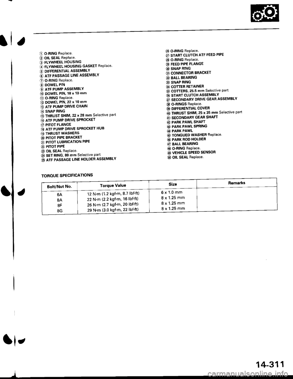
C O-RING Replace.
e) OIL SEAL RePlace.' FLYWHEEL HOUSING
O flVWneel }|OUSttttG GASKET Replace
6 DIFFERENTTALASSEMELY
@ lrr plsslce uruE ASSEMBLY
O O-RING Replace
@ DOWEL PIN
€) ATF PUMP ASSEMBLY(O DowEL PlN, 18 x 10 mm
O O-RING Replace.o DowEL PlN, 22 x 10 mm
lrr puup oRve cxltttt
iA SNAP RING
f3 fxaUst St|t|l, zz t 28 mm Selective part
Gt lrr punp ontve spaocxer
O PITOT FLANGE
ito nTF purrap ontve SPRoGKET HUB
(O THRUST WASHERS
@ PITOT PIPE BRACKET
O PITOT LUBRICATION PIPE
@ PITOT PIPEt3 OIL SEAL Replace.
Oa SEt AtitC, SO mm Selective Part
o3 lrr passlce ltnE HoLOER ASSEMBLY
6) o-RING Replace.
€) START CLUTCH ATF FEED PIPE
CO O-RING Replace.
€I FEEO PIPE FLANGE
@ SNAP RING
O' CONNECTOR BRACKET
@ BALL BEARING
6} SNAP RING64 COTTER RETAINER6D CoTTERS,25.5 mm selective Part6t stlnt cLutcH asseMsLv
@ secoruomv ontvE GEAR ASSEMBLY
@ o-RINGS Replace
6) DIFFERENTIAL COVER
rO ttaUSr SntU, zs t 35 mm Selective part
@ SECONDARY GEAR SHAFT
@ PARK PAWL SHAFT
@ PARK PAWL SPRING.1i PARK PAWL
@ TONGUED WASHER REPIACE,
@ PARK ROO HOLDER
@ BALL BEARING
@ o-RING Replace.
@ VEHICLE SPEED SENSOR
@ OIL SEAL Replace.
ft,
)
TOROUE SPECIFICATIONS
6x1.0mm
8 x 1.25 mm
8 x 1.25 mm
8 x 1.25 mm
12 N.m (1.2 kgnm,8.7 lbf'ft)
22 N.m (2.2 kgf'm. 16lbf'ft)
26 N.m (2.7 kgf'm, 20 lbf'ft)
29 N.m {3.0 kgf'm, 22 lbift)
14-311
Page 991 of 2189
Transmission Housing/Lower Valve Body Assembty
Removal
NOTE:
. Clean all parts thoroughly in solvent or carburetor cleaner, and dry with compressed air.. Blow out all passages.
. When removing the lower valve body, replace the followingl- O-rings- ATF pan gasket- Sealing washers
DOWEL PIN
ATF STRAINER
6 x 1.0 mm BOLT
ATF PAN GASKETReplace.
ATF COOLER INLET LINEBRACKET BOLT8 x 1.25 mm
ATF COOI..ER INLET LINE
O.RINGReplace.
SOLENOIO HARNESS CONNECTOR
6 x'1.0 mm BOLT
LOWER VALVE BODY ASSEMBLY
6 x 1.0 mm BOLT
14-314
6 x 1.0 mm EOLT
Page 992 of 2189
l.
'1.
2.
5.
6.
7.
Remove the ATF cooler inlet iine bracket bolt'
Remove the ATF cooler outlet line
Remove the ATF pan (fourteen bolts).
Remove the ATF strainer {two bolts)
Remove the one bolt securing the solenoid harness
connector, then push the connector.
Remove the lower valve body (eight bolts)
Clean the inlet opening of the ATF strainer thoroughly
with compressed air, then check that it is in good
condition, and the inlet opening is not clogged'
ATF STRAINER
INLET OPENING
Replace the ATF strainer if it is clogged or damaged
NOTE: The ATF strainer can be reused it it is not
clogged.
2c'
c;2 ar\
14-315
Page 1021 of 2189
l.
60. Install the ditferential assembly
61. Installthe ATF passage line assembly with new O-rings (one boltl'
62. Install thethreedowel pinsand new flywheel housing gasket on the transmission housing'
63. Install the flywheel housing and connector bracket (twenty bolts)'
64. Installthe ATF passage line holder assembly (two bolts)'
8 x 1.25 mm29 N.m t3.o kg['m, 22 lbf'ttl
IATF PASSAGE L|NE I"o.o.'o{
d
rm
\A
o-nrnc--.-..ff
FLYWHEEL HOUSINGGASKET
6x1.0mm12 N.m {1.2 ksf'm,
8.7 tbf.ftl/g
ugs llFLYWHEEL HOUSING
CONNECTOR BRACKET
DOWEL PIN
DIFFERENNAL ASSEMBLY
DOWEL PIN
ATF PASSAGE LINE
ASSEMALY
6x1.0mm12 N.m 11.2 kgd'm,
8.7 tbr.tr)
O.RING
DOWEL PIN
TRANSMISSIONItousrNG
ATF PASSAGELINE ASSEMBLY
PASSAGE LINEGUIOE
(cont'd)
TRANSMISSION HOUSING
14-345
Page 1022 of 2189
Transmission
Reassembly (cont'dl
65 lnstall the solenoid harness connector with a new O-ring (one bolt), then install the lower valve body assembly withthree dowel pins (eight bolts).
66. Install the ATF strainer with a new O-ring (two bolts).
67. lf necessary, assemble the ATF pan, ATF filter, and the ATF cooler inlet line (see page 14_303).
68. Install the ATF pan with the two dowel pinsand a new ATF pan gasket (fourteen bolts).
69. Install the ATF cooler inlet line bracket bolt.
70. Installthe ATF cooler outlet line with the line bolt and new sealing washers.
6x1.0mm12 N.m 11.2 kgf.m,8.7 rbtft)DOWEL PINS
ATF STRAINER
DOWEL PINS
ATF PAN,/ATF FILTER/ATF COOLER INLETLINE ASSEMELY
@
@
C4
CONNECTOE
6x1.0mm12 N.m {1.2 kgf.m,8.7 tbtftl6x1.0mm12Nm11.2kgl.m,8.? tbf.ft)
LOWER VALVE BODYASSEMBLY
6x1.0mm12 N.m 11.2 kgf.m,8.7 tbt.ft)
ATF COOI.ER INI.ITLINE BRACKET BOLTI x 1.25 mm26 N.m (2.7 kgt.m, 20 lbf.ft)
ATF COOLER OUTI.IT LINE
14-346