Page 989 of 2189
lllustrated Index
Right Side Cover/lntermediate Housing
88
I.Fi.
Page 1299 of 2189
Glove box removal:
Remove the bolts, then remove the glove box.
>: Bolt locations,2
Installation is the reverse of the removal proceoure
Side air vent/Side defogger trim removal:
SIOE DEFOGGER TRIMSHOPTOWET_Carefully PrY rt at the
then remove it,side edge,
SIDE AIR VENTRemove the driver's dashboard lower
cover, or oPen the glove Dox,
HOOKS
then push the cliPs from each
opening by hand, and Pull it
out. Disconnect the connedors(driver's side).
HOOKS
DASH LIGHTSBRIGHTNESSCONTROLLERCONNECTOR{for some models)
CFUISE CONTROLMASTER SWITCHCONNECTOR(for some models)
Center dashboard lower covel:
1. Remove:
. Driver's dashboard lower cover
. Glove box
2. Remove the screws and bolt, then remove the cen-
ter dashboard lower cover. Disconnect the accesso-
ry socket connector'
>i Boh, screw locations
a>, 1 B>'5
A s*o.e-- I A
@;*;ry'-1'-.J _e)
3. Installation is the reverse of the removal proceoure'
(cont'd)
20-69
LOWER COVER
Page 1309 of 2189
Rear Seat
Removal
NOTE: Take care not to scratch the seat covers and body.
4D:
>: Bolt locationsl_):Hook locations,2
b,,***-,,.1*
D>'
] >mr
;iffiP-"*'piii::#r-,'-, @t,V . se-ri-cusxo" [-6*
v-
2u
2u
SEAT CUSHION
SEAT-BACK
Pivot boll conslruction:
SLITS
lnstallation is the reverse of the removal procedure
PIVOT BOLT ERACKET8 x 1.25 mm22 N m (2.2 kgf m, 16lbtftl
Apply liquid thread lock
NOTE:
. Before attaching the seat-back and seat cushion, make sure there are no twists or kinks in the rear seat belts and
center belt.
. When installing the seat cushion, slip the seat belt buckles through the slits in the seat cushron'
. Make sure the seat-back locks securely.
. lf necessary, adiusr the seat-back latch (see page 20-82) and seat-back (cont'd)
c>,1
6x1.omm l1Q- e "r.o--s.a ru.- tr.o rer-. I s.i N.- ir.o lgr.,i7.2 lbf.ft) ) E 7.2 'tJrftl
:- '/
>: Clip locations, 14
"@rz, \
EEES/
_ _ot /
RIGHT SEATSIDE EOLSTER
CENTEBPIVOTBRACKET
20-79
Page 1679 of 2189

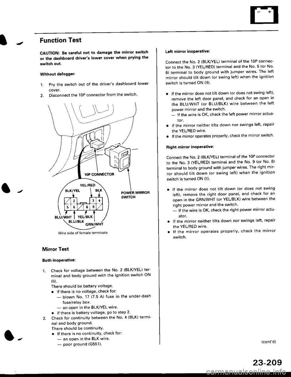
Function Test
CAUTION: Be careful not to damage the mirror switch
or the dashboard drivel's lower covel when prying the
swhch out.
Withoui defogger:
1. Pry the switch out of the driver's dashboard lower
cover.
2. Disconnect the 10P connector from the switch.
lOP CONNECTOR
BLU/WHT
YEL/RED
BLK/YELBLK
4
568
YEL/BLK
POWER MIRRORswtTcH
\:/"*jgil*-(
Wire side of female termanals
Mirror Test
Both inoperative:
1. check for voltage between the No. 2 (BLVYEL) ter
minal and body ground with the ignition switch ON
0 r).
There should be batterY voltage
. If there is no voltage, check for:
- blown No. 17 (7 5 A) fuse in the under-dash
tuse/relay box- an open in the BLK'/YEL wire.
o lf there is battery voltage, go to step 2.
2. Check for continuity between the No 4 (BLK) termi-
nal and body ground.
There should be continuity.
. lf there is no continuity, check for:
- an open in the BLK wire.
- poor ground (G551).
Left mirror inoporalive:
connect the No. 2 {BLK/YEL) terminal of the 10P connec-
tor to the No. 3 (YEURED) terminal and the No 5 (or No
6) terminal to body ground with jumper wires The left
mirror should tilt down (or swing left) when the ignition
switch is turned ON (ll)
. lf the mirror does not tilt down (or does not swing left),
remove the left door panel. and check for an open in
the BLU/WHT (or BLU/BLK) wire between the left
power mirror and the switch
- lf the wire is OK. check the left power mirror actua-
tor.
lf the mirror neither tilts down nor swings left. repair
the YEURED wire.
lf the mirror operates properly, check the mirror switch'
Right mirror inoperative:
Connect the No. 2 (BLK /EL) terminal of the 10P connector
to the No. 3 (YEURED) terminal and the No. 9 (or No 8)
terminal to body ground with jumper wires The right mir-
ror should tilt down (or swing left) when the ignition
switch is turned ON (ll).
. lf the mirror does not tilt down (or does not swlng
left), remove the right door panel. and check for an
open in the GRN/WHT (or YEUBLK) wire between the
right power mirror and the switch.
- lf the wire is OK, check the right power marror actu-
ator.
. lf the mirror neither tilts down nor swings left. repair
the YEURED wire
. lf the mirror operates properly, check the mirror
switch.
(cont'd)
23-209
Page 1682 of 2189
Power Mirrors
Power Mirror Test
1. Pry out the cover panel (see section 20).
Terminalside ofmale terminals
*: Canada '99 - 00 models
Disconnect the 8P connector from the power mirror.
Check actuator operation by connecting power and
ground according to the tables.
Dofogger Test:
4. Check for continuity between the No. 3 and No. 4
terminals of the 8P connector.
There should be continuity.
COVER
L___r"'ry1Position67I
TILT UPo@
TILT DOWN@
SWING LEFTo@
SWING RIGHT@
23-212
Mirror Actuator Replacement
(Donnelly Typel
'1. Remove the power mirror from the door {see sec-
tion 20). and disconnect the 8P connector.
2. Remove the mirror base cover from the mirror
housing.
MIRROR HOLDER
Remove the mirror holder from the mirror housing.
Gently pull it out by hand.
Remove the three screws from the actuator and the
two screws from the bracket at the base of the
assemory.
BRACKET
5. Remove the bracket from the housinq.
4.
MIRROR HOUSING
Page 1814 of 2189

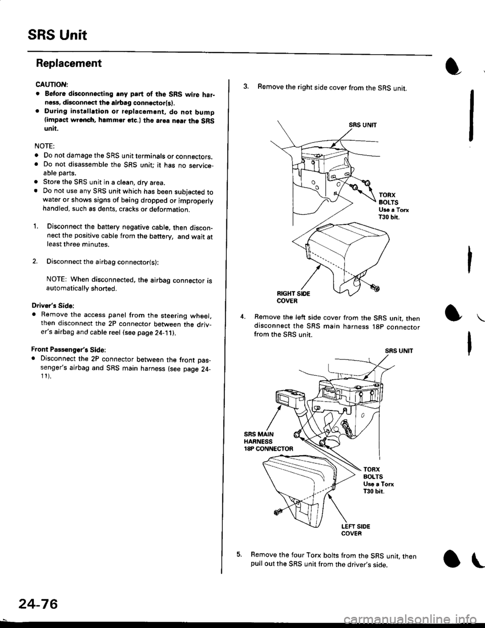
SRS Unit
Replacement
CAUTION:
. Betore disconnoqting lny pErt of the SRS wire hal-ness, disconnect th9 airbag conn"ctorlsl.. During installltion or teplacemsnt. do not bump(impact w.cnch, hamm€r stc.l the area noar tho SRSunit.
NOTE:
o Do not damage the SRS unit terminals or connectors.. Do not disassemble the SRS unit; it has no service-able parts,
. Store the SRS unit in a clean, dry a.ea,. Do not use any SRS unit which has be€n subjected towater or shows signs of being dropped or improperlyhandled. such 8s dents, cracks or deformation.
1. Disconnect the bsttery negative cable. then discon-nect the positive cable from the battery, and wait atleast three minutes.
2. Disconnect the airbag connector{s}:
NOTE: When disconnected, the airbag connector isautomatically shorted,
Driver's Side:
. Remove the access panel from the steering wheel.then disconnect the 2P connector between the driv_er's airbag and cable reel (see page 24-11).
Front Passenge/s Side:. Disconnect the 2P connector between the tront oas_senger's airbag and SRS main harness (see page 24-11).
24-76
o\
3. Remove the right side cover from the SRS unit.
SRS UNTT
TOBXBOLTSUge a TorxT30 bit.
RIGHT SIOE
Remove the left side cover from the SRS unit, thendisconnect the SRS main harness lgp connectorfrom the SBS unit.
SRS UNIT
5. Remove the four Torx bolts from the SRS unit, thenpull out the SRS unit from the driver,s side,
COVER