Page 177 of 2189

Removal
Engine removal is not required for this procedure.
!@@ Make sure jacks and safety stands are placed
properly and hoist brackels are attached to correst posi-
tion on the engine,
CAUTION:
o Use fender covers to avoid damaging painted sur-
faces.
To avoid damage, unplug the wiling connectors
carelully while holding the connector portion.
To avoid damaging the cylinder head, wait until the
engine coolant temperature drops below 100"F {38'Cl
before loosening the retaining bolt.
NOTE:
. Unspecified items are common.
. Mark all wiring and hoses to avoid misconnection.
AIso, be sure that they do not contact other wiring or
hoses or interfere with other parts.
o Inspect the timing belt before removing the cylinder
n eao.
. Turn the crankshaft pulley so that the No. 1 piston is
at top dead center (see page 6-64).
1. Disconnect the negative terminal from the battery.
Drain the engine coolant {see page 10-7).
. Remove the radiator cap to speed draining.
Remove the strut brace (see page 5-2).
Remove the intake air duct and air cleaner housing
(see page 5-3).
Remove the adjusting bolt and mounting bolt, then
remove the power steering (P/S) pump belt and pump
(see page 5 5).
2.
3.
4.
\
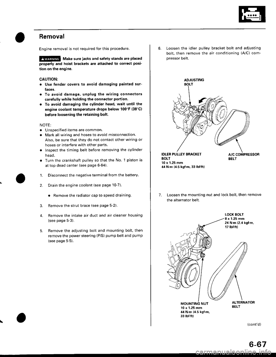
ADJUSTING
6. Loosen the idler pulley bracket bolt and adjusting
bolt, then remove the air conditioning (A/C) com-
pressor belt.
IDLER PULLEY BRACKETBOLT10 x 1.25 mm44 N.m {4.5 kg,l.m, 33 lbt.ft}
7. Loosen the mounting nut and lock bolt, then remove
the alternator belt.
LOCK BOLT8 x 1.25 mm24 N.m {2.4 kgf.m,17 tbtftl
ALTERNATORBELT10 x 1.25 mm,l,l N.m {4.5 kgf.m,33 tbf.ft,
(cont'd)
6-67
Page 183 of 2189
Rocker Arms and Lost Motion Assemblies
Inspection
NOTE: When reassembling the primary rocker arm, care-
fully apply air pressure to the oil passage of the rocker
arm.
PRIMARY ROCKER ARM
MID ROCKER ARM
Inspect each rocker arm piston. Push it manually
- lf it does not move smoothly. replace the rocker
arm assemDly.
1.
SECONDARY
Check prston movement
NOTE:
. Apply oilto the pistons when reassembling.
. Bundle the rocker arms with a rubber band to
keep them together as a set.
PISTONS
PRIMARY
\
6-73
2. Remove the lost motion assembly from the cylinder
head and inspect it. Test it by pushing the plunger
with your finger,
- lf the lost motion assembly does not move
smoothly, replace it.
LOST MOTION ASSEMBLY
Push
I
Page 194 of 2189

I
Cylinder Head
Installation
lnstall the cylinder head in the reverse order of removal:
NOTE:
. Always use a new head and manifold gasket.. The cylinder head gasket is a metal gasket, Take carenot to bend it.
. Rotate the crankshaft, set the No. 1 piston at TDC (seepage 6-63).
. Do not use the middle cover and lower cover forstorang removed items.. Clean the middle cover and lower cover before instal_lation.
o Replace any washers that are damaged or deteriorated.
1. Install the cylinder head gasket, dowel pins and thehead oil control orifice on the cylinder head.
NOTE: Clean the oil control orifice when installing.
DOWEL PIN
6-84
2, Tighten the cylinder head bolts in two steps. In thefirst step, tighten all bolts in sequence to about 29N.m (3.0 kgf.m, 22 tbf.ftl. ln the final step, tighten inthe same sequence to 83 N.m (8.S kgf.m,6t lbf.ft).
NOTE:
. Apply clean engine oil to the bolt threads andunder the bolt head.. We recommend using a beam-type torquewrench. When using a preset-type torque wrench,be sure to tighten slowly and not to overtighten.. lf a bolt makes any noise while you are torquing it,loosen the bolt, and retighten it from the 1st step.
CYLINDER HEAD BOLT TOROUE SEOUENCE
11x 1.5 mm83 N.m 18.5 kgf.m, 61 tbf.ftl
Install the intake manifold and tighten the nuts in acflsscross pattern in two or three steps, beginningwith the inner nuts.. Always use a new intake manifold gasket.
Install the exhaust manifold and tighten the newself-locking nuts in a crisscross pattern in two orthree steps. beginning with the inner nuts.. Always use a new exhaust manifold gasket.
4.
Page 198 of 2189

Engine Block
Speciaf Tools ..........." 7-2
lllustlated Index ...................."..'.......... 7-3
Flywheel and Drive Plate
Repf acement """'.' 7-7
Connecting Rod and Crankshaft
End Play ..........."....7-8
Main Bearings
Clearance ............... 7-9
Selection ................7-10
Connecting Rod Bearings
clearance ....'.......... 7-11
Selection ................ 7-11
Pistons and Crankshaft
Removaf ................. 7 -12
Crankshaft
Inspection ."".........7-14
Pistons
Inspection ......"'.....7-15
fnstaffation .............7-23
Cylinder Block
lnspec'tion ..............7-16
Bore Honing ..........7-17
Piston Pins
Removal ...,...........'.7-17
lnstallation .............7-18
Inspection .'............7-19
Connecting Rods
Selection ................7-18
Piston Rings
End Gap ..........".."' 7'2O
Repfacement .........7-2O
Ring-to-Groove Clearance ...........'.'. 7 -21
Afignment .......""'.. 7'21
Crankshaft Oil Seal
fnstaffation .............7-22
Crankshaft
fnstaffation ..-.-..'.".' 7'23
Oil Pan
lnstallation .............7-26
Oil Seals
fnstaffation ....""""' 7-29
r-f
Page 199 of 2189
Special Tools
Ref. No. I Tool Numbel
o
aal
@
o
@6'
@
o
07LAB - PV00100
07749 - 0010000
07947 - SB00200
07948 - SB00'101
07973 - PE00200
07973 - PE00310
07973 - PE00320
07973 - PE00400
07973 - S800100
07973 - 6s70500
07973 - 6570600
Ring Gear Holder
Driver
Seal Driver
Driver Attachment
Pilot Collar
Piston Pin Driver Shaft
Piston Pin Driver Head
Piston Pin Base Insert
Piston Base Head
Piston Base
Piston Base Spring
1-7
7-22,29
7.29
7-22,29
7-17,18'7 -17, 1a
7-11, 1A
7 -17, 18
1-17, 18
7-17,18
7-17,18
Y(\!
a.:
ai
C
a
Eg
ot0arll
a
7-2
\
Page 203 of 2189

lllustrated Index
(cont'd)
NOTE: New rod bearings must be selected by matching connecting rod assembly and crankshaft(see page 7,11).identification markings
Lubricate all internal parts with engine oil duringreassembtv.
PISTON INSTALLATION DIRECTION:
EXHAUST
4\/=\6\z\
\e/!rqrf/
INTAKE
PISTON RINGSReplacement. page 7-20Measurement, pages 7 20 andj-21Alignment, page 7-21
PISTON PINRemoval, page 7,17Installation, page 7-18Inspection, page 7,19
CONNECTING RODEnd play, page 7-8Selection, page 7,18
CONNECTING RODBEARINGSClearance, page 7 11Selection, page 7-11
CONNECTING ROD BEARING CAPInstallation, page 7-23NOTE: lnstall caps so thebearing recess is on thesame side as the recessin the rod.
PISTONInspectron, page 7-15NOTE: Betore removing the piston, inspect thetop of the cylinder bore for carbon build-up orridge. Bemove ridge if necessary, page 7-13
ENGINE BLOCKCylinder bore inspection, page 7-16Warpage inspection, page 7,'16Cylinder bore honing, page 7,17
Inspect top of each cylinder borefor carbon build-up or ridgebefore removing piston.Remove ridge if necessary, page 7-13
CONNECTING ROD CAP NUT816A2 €ngin6:9 x 0.75 mm{0 N.m (4.1 kgt m, 30 tbf.ftlD16Y5, Dl6Y7. D16Y8 engines:8 x 0.75 mm3l N.m {3.2 kg{.m,23 tbt.fr)Apply engine oiltothe bolt threads.NOTE: After torquing each bearingcap, rotate crankshaft tocheck for binding.
7-6
Page 209 of 2189
Pistons and Crankshaft
Removal
1. Remove the oil pan assembly.
2. Remove the right side cover.
816A2 engine
D16Y5, Dl6Y7, D16Y8 ongines
RIGHT SIDE
7-12
\
3. Remove the oil screen.
4. R€move the oil pump.
816A2 engin€
OIL SCREEN
D16Y5, D1oyr, D16Y8 engin.s
O-RINGReplace.
5, Remove the baffle plate (816A2 engine).
OIL PUMP
Page 210 of 2189

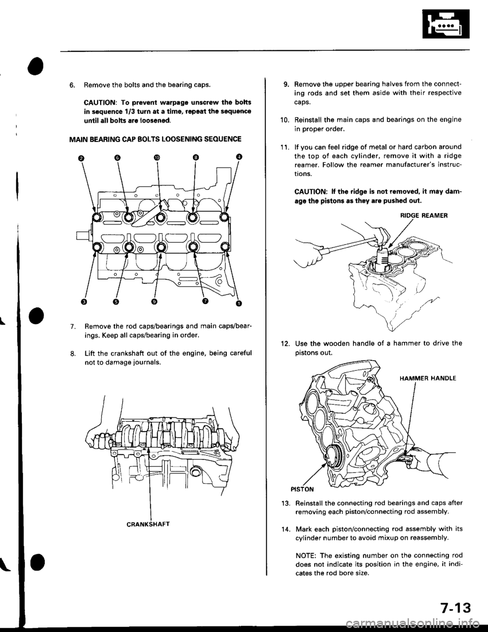
6. Remove the bolts and the bearing caps.
CAUTION: To prevenl warpago unscrow lhe bolts
in s€quence 1/3 turn at a tims, r€paat the soquence
until all bolts ar€ loo3ened.
MAIN BEARING CAP BOLTS LOOSENING SEOUENCE
Remove the rod caps/bearings and main capvbear-
ings. Keep all caps/bearing in order.
Lift the crankshaft out of the engine, being careful
not to damage journals.
7.
S:_]ILOJLOAO
CRANKSHAFT14.
7-13
qRemove the upper bearing halves from the connect-
ing rods and set them aside with their respective
caos.
Reinstall the main caps and bearings on the engine
in proper order,
lf you can feel ridge of metal or hard carbon around
the top of each cylinder, remove it with a ridge
reamer. Follow the reamer manufacturer's instruc-
I|ons.
CAUTION; lf the ridge is not removed, it may dam-
age tho pistons as they are pushod out.
RIOGE REAMER
10.
11.
12.Use the wooden handle of a hammer to drive the
pastons out.
13.Reinstall the connecting rod bearings and caps after
removing each piston/connecting rod assembly.
Mark each piston/connecting rod assembly with its
cylinder number to avoid mixup on reassembly.
NOTE: The existing number on the connecting rod
does not indicate its position in the engine, it indi-
cates the rod bore size.