Page 1276 of 2189

Ouarter Glass
1.
Installation
Using a knife, scrape the old adhesive smooth to athickness of about 2 mm (0.08 in.) on the bondingsurface around the entire quarter glass openingflange.
NOTE:
. Do not scrape down to the painted surface of thebody; damaged paint will interfere with proper
a
a
bonding.
Remove the fastener from the body.lf any of the clips are broken, remove lhem fromthe body.
Mask off surrounding surfaces before applyingpnmer.
Clean the body bonding surface with a sponge dampened in alcohol.
NOTE: After cleaning, keep oil, grease and waterfrom getting on the surface.
lf the quarter glass is to be reinstalled, use a puttyknife to scrape off all traces of old adhesive. thenclean the quarter glass surface with alcohol whereadhesive is to be applied.
NOTE: Make sure the bonding surface is kept freeof water. oil and grease.
CAUTION: Avoid setting the quarter glass on itsodges; small chips may later develop into cracks,
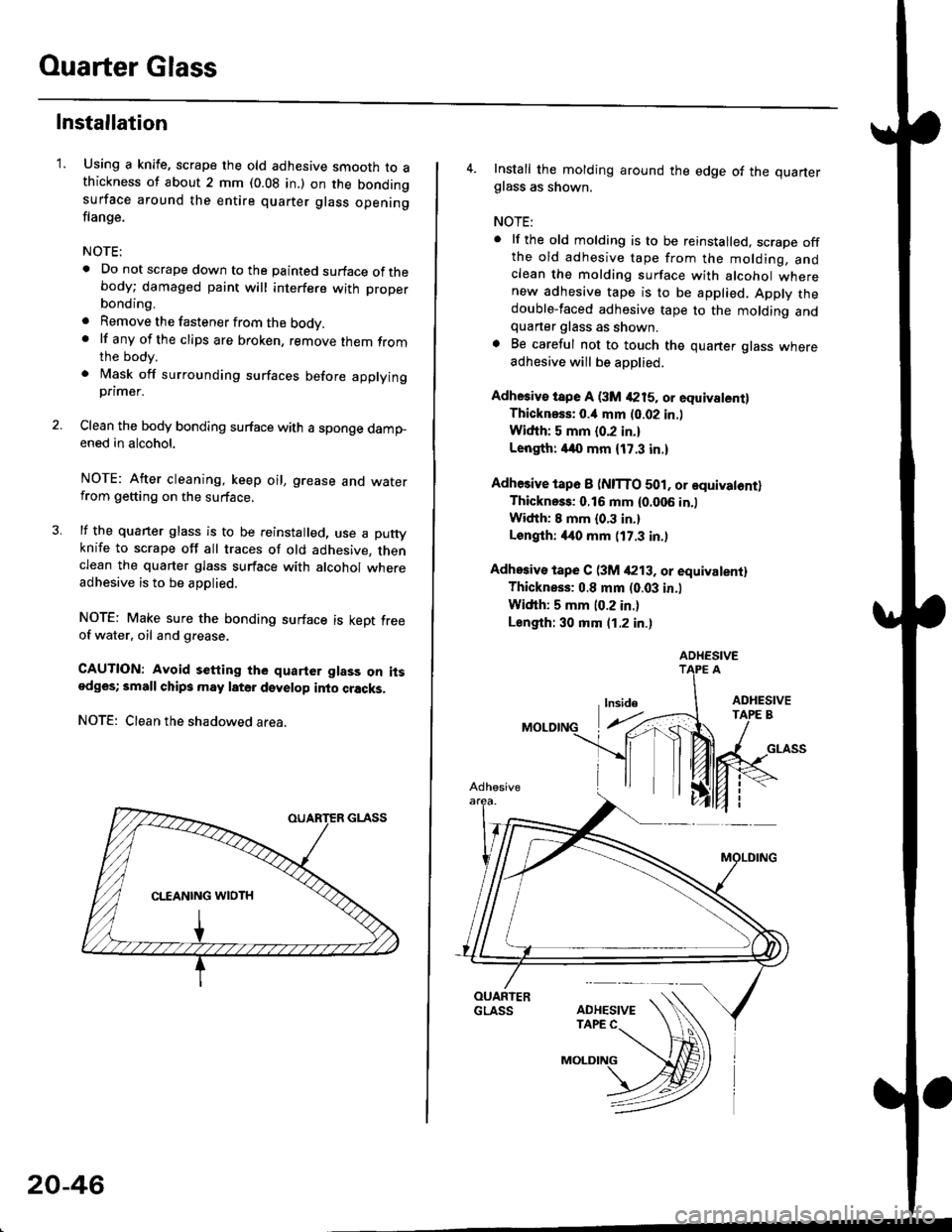
NOTE: Clean the shadowed area.
20-46
4. Install the molding around the edge of the quarterglass as shown.
NOTE:
. lf the old molding is to be reinstalled, scrape offthe old adhesive tape from the molding, andclean the molding surface with alcohol wherenew adhesive tape is to be applied. Apply thedouble-faced adhesive tape to the molding andquarter glass as shown.. Be careful not to touch the quarter glass whereadhesive will be aoDlied.
Adhesiv€ tspe A (3M 4215, or equivalent)Thicknsss: o.il mm (0.02 in.l
Widih: 5 mm {0.2 in.}
Length: /140 mm {17.3 in.)
Adhesive tap6 I (NITTO 501, or equivatontlThickness: 0.16 mm {0.006 in.)
Width: I mm {0.3 in.}
Longlh: 4it0 mm (17.3 in.)
Adhosiv€ tape C (3M /P13. or equivalentl
Thickness: 0.8 mm (0.03 in.l
Width: 5 mm (0.2 in.)
Length: 30 mm (1.2 in.)
ADHESIVE
Page 1569 of 2189

JBrush Holder Test
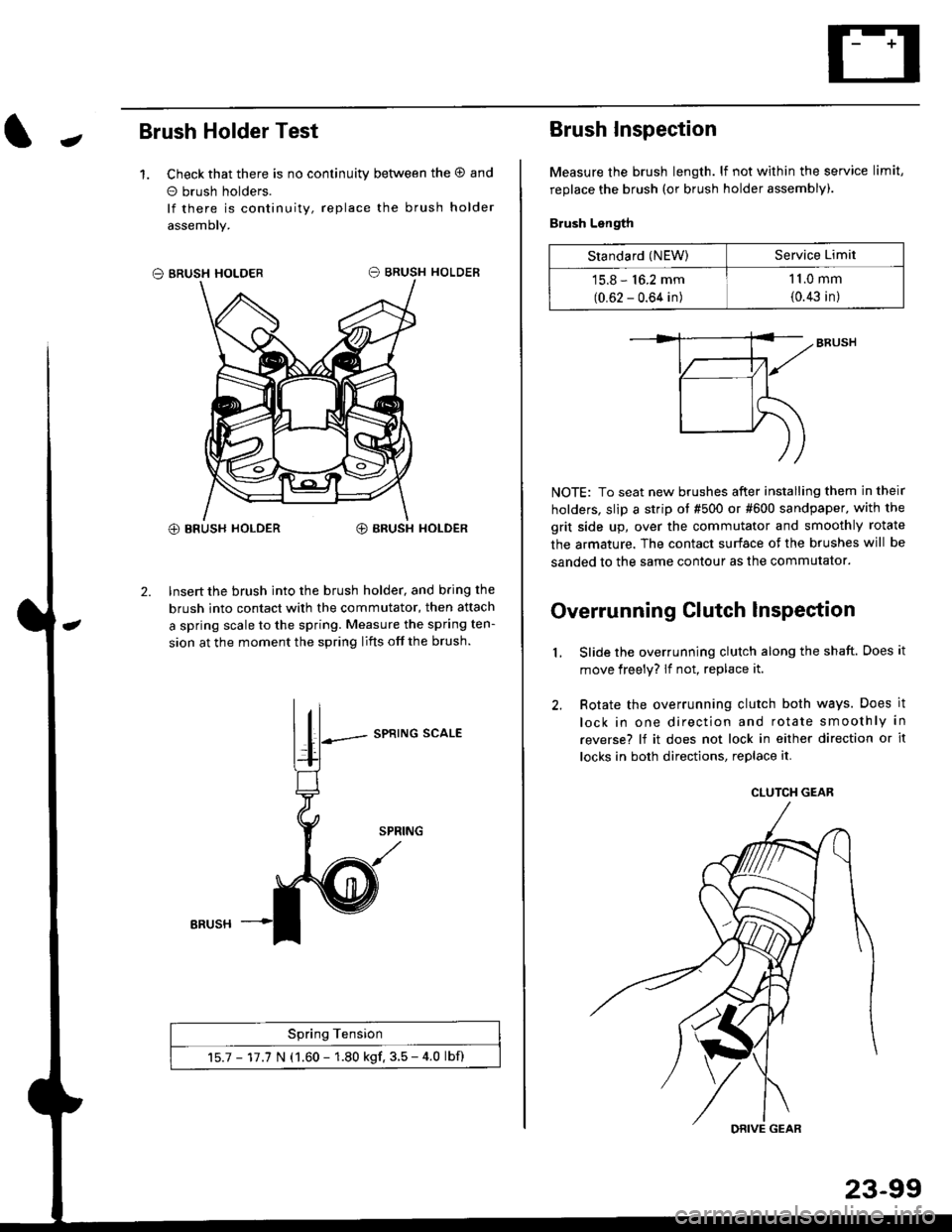
1. Check that there is no continuity between the O and
o brush holders.
lf there is continuity, replace the brush holder
assemoly.
O BRUSH HOLDER
@ BRUSH HOLDER€) BRUSH HOLDER
2. Insert the brush into the brush holder, and b.ing the
brush into contact with the commutator, then attach
a spring scale to the spring. Measure the spring ten-
sion at the moment the spring lifts off the brush.
SPRING SCALE
Spring Tension
15.7 - 17.7 N (1.60 - 1.80 kgf. 3.5 - 4.0 lbf)
ERUSH
Brush Inspection
Measure the brush length. lf not within the service limit,
replace the brush (or brush holder assembly).
Brush Length
NOTE: To seat new brushes after installing them in their
holders, slip a strip ot #500 or #600 sandpaper. with the
grit side up, over the commutator and smoothly rotate
the armature. The contact surface of the brushes will be
sanded to the same contour as the commutator.
Overrunning Clutch lnspection
Slide the overrunning clutch along the shaft. Does it
move freely? lf not, replace it.
Rotate the overrunning clutch both ways. Does it
lock in one direction and rotate smoothly in
reverse? lf it does not lock in either direction or it
locks in both directions, replace it.
2.
L
Standard (NEW)Service Limit
15.8 - 16.2 mm
(0.62 - 0.64 in)
1 1.0 mm
{0.43 in)
CLUTCH GEAR
DRIVE GEAR
Page 1593 of 2189

JRotor Slip Ring Test
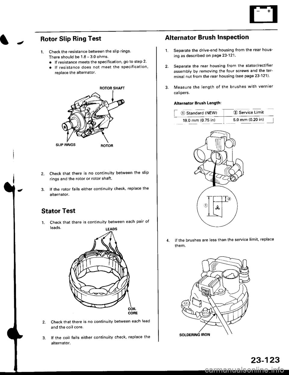
1. Check the resistance betlveen the slip rings
There should be 1 8 - 3 0 ohms
. lf resistance meets the specification, go to step 2.
. lf resistance does not meet the specification,
reolace the alternator'
SLIP BINGS
2. Check that there is no continuity between the slip
rings and the rotor or rotor shaft.
3. lf the rotor fails either continuity check, replace the
alternator.
Stator Test
'1. Check that there is continuity between each pair of
leads.
CORE
Check that there is no continuity between each lead
and the coil core.
lf the coil fails either continuity check, replace the
alternator.
ROTOR SHAFT
LEADS
1.
Alternator Brush InsPection
Separate the drive-end housing from the rear hous-
ing as described on page 23-121
Separate the rear housing from the stator/rectifier
assembly by removing the four screws and the ter-
minal nutfrom the rear housing {see page 23-121}
lvleasure the length of the brushes with vernrer
calrpers.
Alternator Brush Length:
O Standard {NEW} @ Service Limit
19.0 mm (0.75 in) 1 5.0 mm (0 20 in)
lf the brushes are less than the service limit, replace
them.
23-123