Page 1630 of 2189

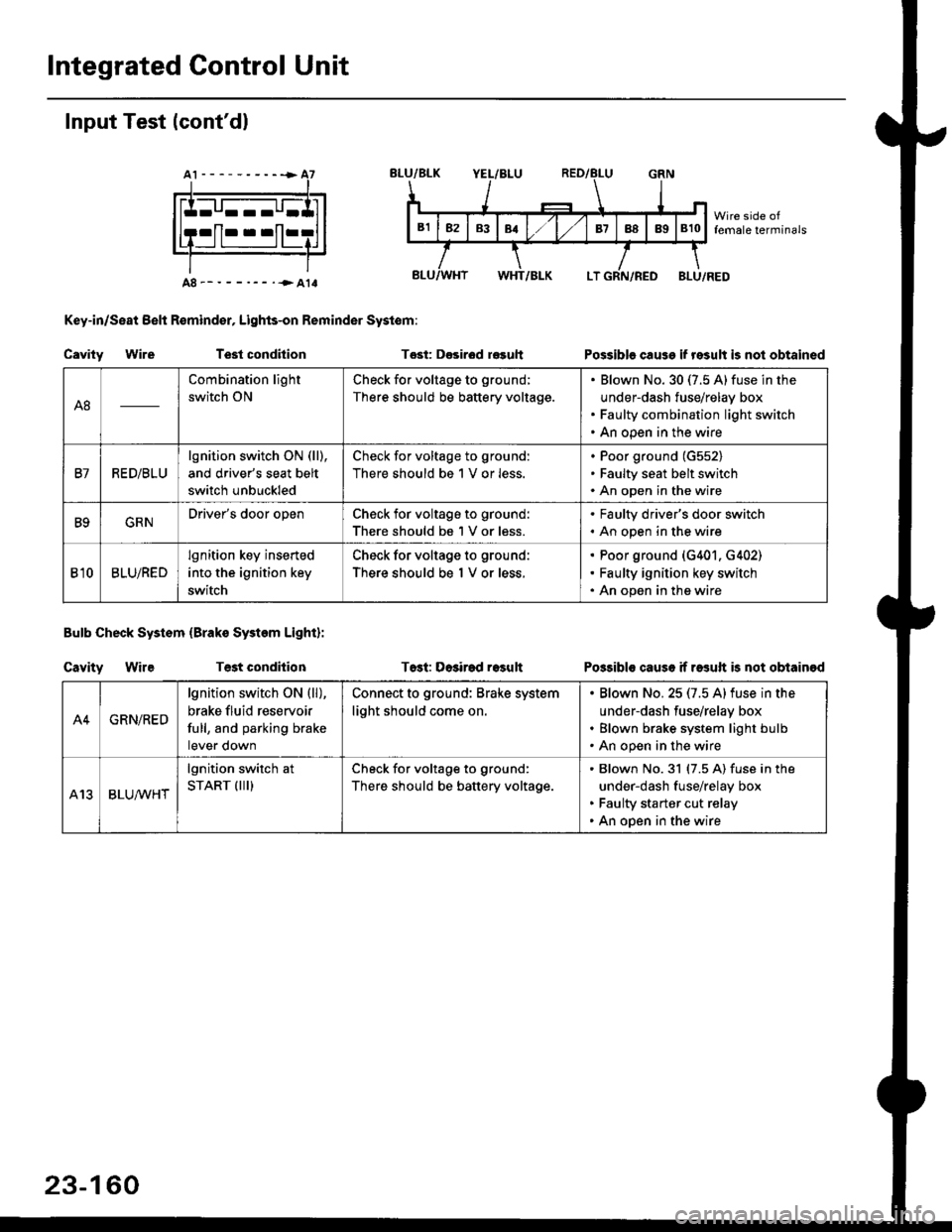
Integrated Gontrol Unit
Input Test (cont'dl
A8--------.--all
Key-in/Seat Belt R€mind€r, Lights-on Reminder Systom:
Cavity WireTest condhion
Bulb Check System (Brako System Light):
Cavity WireTest condilion
Tost: D€sirod r€guh
T6st: Dosirad result
Possible cause if result is not obtained
Possibls cause if rasuft b not obtainod
A8
Combination light
switch ON
Check for voltage to ground;
There should be battery voltage.
Blown No.30 (7.5 A)fuse in the
under-dash fuse/relay box
Faulty combination light switch
An open in the wire
B7RED/BLU
lgnition switch ON (ll),
and driver's seat belt
switch unbuckled
Check for voltage to ground:
There should be 1 V or less.
Poor ground (G552)
Faulty seat belt switch
An open in the wire
B9GRNDriver's door openCheck for voltage to ground:
There should be 1 V or less.
. Faulty driver's door switch. An open in the wire
Bl0BLU/RED
lgnition key inserted
into the ignition key
switch
Check for voltage to ground:
There should be 1 V or less.
Poor ground (G401. G402)
Faulty ignition key switch
An open in the wire
A4GRN/RED
lgnition switch ON {ll),
brake fluid reservoir
full, and parking brake
tever oown
Connect to ground: Brake system
light should come on.
Blown No.25 (7.5 Alfuse in the
under-dash fuse/relay box
Blown brake system light bulb
An open in the wire
A13BLUA/1r'HT
lgnition switch at
START (III)Check for voltage to ground:
There should be battery voltage.
Blown No.31 (7.5 A) fuse in the
under-dash fuse/relay box
Faulty starter cut relay
An open in the wire
23-160
Page 1945 of 2189

- How the Circuit Works
The anti-lock brake system (ABS) prevents locking
of the wheels as a result of heavy braking and/or
poor lraction. A vehicle with locked wheels cannot
be steered. The anti-lock brake system controls the
application of the brakes, allowing the driver to
maintain control of the steering.
Under anti-lock conditions, the antilock brake
system (ABS) modulates the pressure of the brake
tluid to each brake caliper. This system is a four
channel system: the pressure at each caliper is
controlled independently of the pressure al any
other caliper. Whenever a wheel is likely to lock
dunng braking, the anti-lock brake system
modulates the brake oressure at that wheel. When
the brake pressure is reduced to the point where
there is no longer any possibility of wheel locking,
the system returns to the conventional braking
system mode of operation.
Battery voltage is applied at all times through fuse
63 to the ABS control unit. When the ignition switch
is in ON (ll), battery voltage is supplied to the
control unit through fuse 16. The control unit is case
grounded. Inputs are received from the brake switch
and the individual wheel sensors located at each
wheel. The ABS control unit uses these inputs to
control the modulator solenoid unit. The solenoids
adjust the hydraulic pressure applied to each
calioer.
The ABS control unit has a self-diagnosis function.
When the control unit detects a fault, it turns on the"ABS" indicator and disables the anti-lock brake
system. lf the fault is not in the conventional braking
system, the brakes will continue to operate normally
but without the anti-lock feature.
Refer to the Service Manual (Section '19,
Anti-Lock Brake System) for specific tests or
troubleshooting procedures.
44-3
Page 2165 of 2189

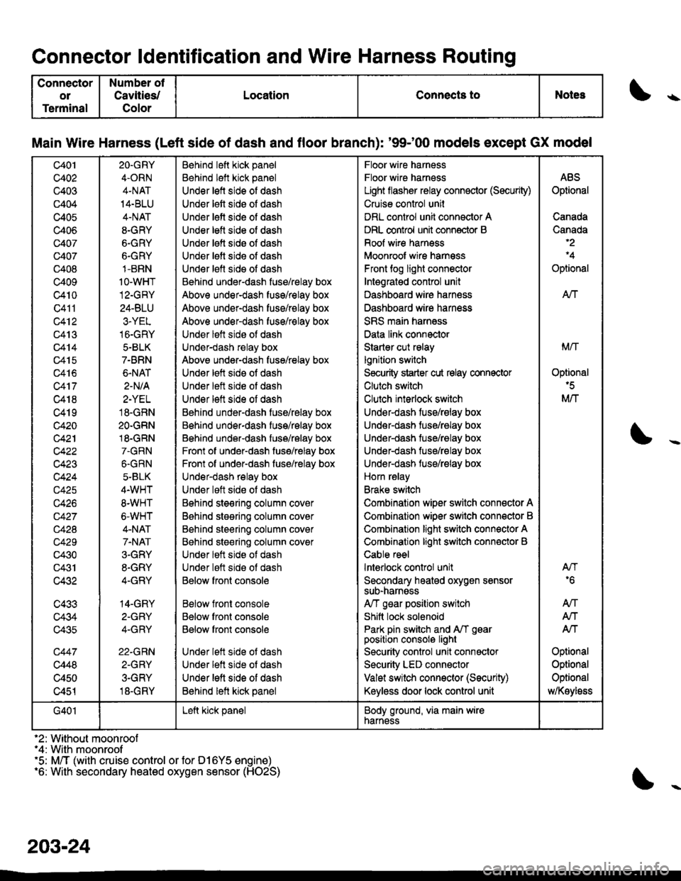
Connector ldentification and Wire Harness Routing
Connector
ol
Terminal
Number ot
Cavlties/
Color
LocationConnects toNotes\
Main Wire Harness (Left side of dash and floor branch): '9$00 models except GX model
c401
c402
c403
c404
c405
c406
c407
c407
c408
c409
c4t0
Q411
c412
c413
c414
c415
c416
c417
c418
c419
c420
c42'l
c423
c424
c425
c426
c42A
c429
c430
c431
c432
c433
c434
c435
c447
c448
c450
c451
2O.GRY
4.ORN
4.NAT
14.BLU
4-NAT
8-GRY
6.GRY
6.GRY
1-BRN
1o-wHT
12-GRY
24-BLU
3.YEL
16-GRY
5.BLK
7-BRN
6.NAT
2-N/A
2-YEL
18.GRN
2O.GRN
18.GRN
7.GRN
6.GRN
5-BLK
4.WHT
8.WHT
6-WHT
4-NAT
7.NAT
3.GRY
8.GRY
4-GRY
14-GRY
2-GFY
4-GRY
22.GRN
2-GRY
3-GRY
18-GRY
Behind left kick panel
Behind left kick panel
Under left side of dash
Under lett side oI dash
Under lett side of dash
Under letl side ol dash
Under lett side oI dash
Under letl side oI dash
Under lefl sids ol dash
Behind under-dash fuse/relay box
Above under-dash fuse/relay box
Above under-dash fuse/relay box
Above under-dash fuse/relay box
Under lett side ot dash
Under-dash relay box
Above under-dash fuse/relay box
Under left side of dash
Under left side ot dash
Under lett side of dash
Behind under-dash fuse/relay box
Behind under-dash fuss/relay box
Behind under-dash fuse/relay box
Front of under-dash fuse/relay box
Front of under-dash fuse/relay box
Under-dash relay box
Under loft side ot dash
Bohind steering column cov6r
B6hind stesring column cover
Behind steering column cover
Behind steering column cover
Under lett side ot dash
Under lett side ot dash
Below fronl console
Below front console
Below front console
Below front console
Under lett side ot dash
Under lett side of dash
Under left side of dash
Behind lett kick panel
Floor wire harness
Floor wire harness
Light flasher relay connector (Sscurity)
Cruise control unil
DRL control unit connector A
DRL control unit conn€ctor B
Roof wire harness
Moonroof wire harnsss
Front tog light connector
Intsgratgd control unit
Dashboard wire harn€ss
Dashboard wire harness
SRS main harness
Data link connector
Starter cut relay
lgnition switch
S€curity starter cut relay connector
Clutch switch
Clulch interlock switch
Under-dash fuse/relay box
Under-dash tuse/ralay box
Under-dash tuse/ralay box
Under-dash fuse/relay box
Under-dash fuse/relay box
Horn relay
Brake switch
Combination wiper switch connector A
Combination wiper switch conn€ctor B
Combination light switch connector A
Combination light switch conn€ctor B
Cable reel
lnterlock control unit
Secondary heated oxygen sensorsub-narnsss
A/T gsar position switch
Shitt lock solenoid
Park pin switch and A/T gearposition consolo light
Security control unit connactor
Security LED connector
Valet switch connector (Security)
Keyless door lock control unit
ABS
Optional
Canada
Canada
Optional
AN
Mrl
Optional'5
M/T
AN'6
An
Atf
Atf
Optional
Optional
Optional
MKoyloss
G401Left kick panelBody ground, via main wirenarness
'2: Without moonroof"4: With moonroof'5: M/T (with cruise control or for D16Y5 engine)'6: With secondary heated oxygen sensor (HO2S)
203-24